Water Furnace TruClimate 700 User manual

General Installation Information................................................................................................ 2
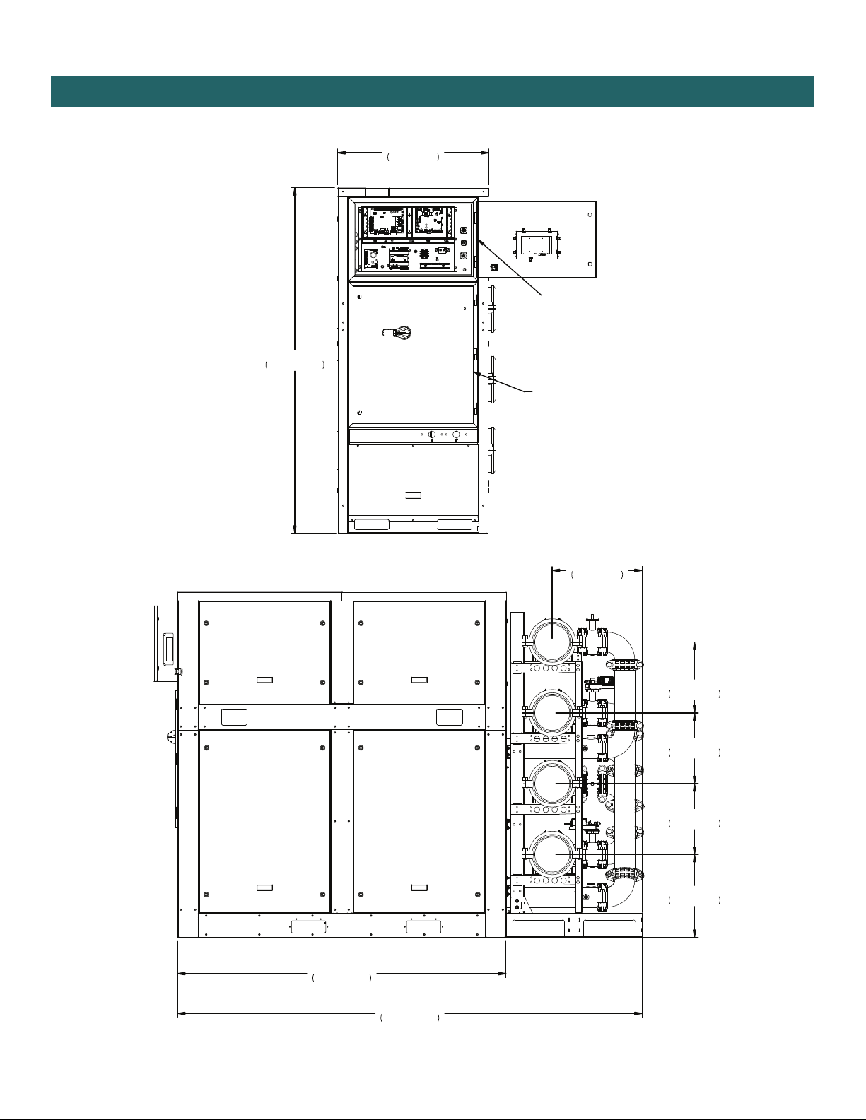
Dimensional Data............................................................................................................................ 3
Physical Data .................................................................................................................................... 9
Installation ......................................................................................................................................... 10
Installation of Bypass/Temperature Headers....................................................................... 14
Removing a Module from the Bank of Units........................................................................ 17
Lifting and Short Distance Transport...................................................................................... 18
High Pressure Refrigerant Relief Venting.............................................................................. 19
Water Connections & Water Quality....................................................................................... 20
Electrical Connections .................................................................................................................. 21
Refrigeration Cycle Analysis....................................................................................................... 22
Revision Guide ................................................................................................................................. 24
This appliance is not intended for use by persons (including
children) with reduced physical, sensory, or mental capabili-
ties, or lack of experience and knowledge, unless they have
been given supervision or instruction concerning use of the
appliance by a person responsible for their safety.
Children should be supervised to ensure that they do not play
with the appliance.
Maximum altitude for this equipment shall not exceed
2000 m.
For installation only in locations not accessible to the
general public.
Installing and servicing air conditioning and heating equip-
ment can be hazardous due to system pressure and electrical
components. Only trained and qualified service personnel
should install, repair or service heating and air conditioning
equipment. When working on heating and air conditioning
equipment, observe precautions in the literature, tags and
labels attached to the unit and other safety precautions that
may apply.
Follow all safety codes. Wear safety glasses and work
gloves. Use quenching cloth for brazing operations. Have fire
extinguisher available for all brazing operations.
NOTE: Before installing, check voltage of unit(s) to ensure
proper voltage.
WARNING: Before performing service or maintenance
operations on the system, turn off main power switches to
the unit. Electrical shock could cause serious personal injury.
WARNING: All WaterFurnace products are designed,
tested, and manufactured to comply with the latest publicly
released and available edition of UL 60335-2-40 for
electrical safety certification. All field electrical connections
must follow the National Electrical Code (NEC) guide
standards and / or any local codes that may be applicable
for the installation.
WARNING: Only factory authorized personnel are approved
for startup, check test and commissioning of this unit.
INSTALLER: Please take the time to read and understand
these instructions prior to any installation. Installer must
give a copy of this manual to the owner.
OWNER: Keep this manual in a safe place in order to provide
your serviceman with necessary information.
All TruClimate 700 90-140 Ton product is Safety listed under UL60335-2-40 thru ETL
UL-60335-1 / CAN/CSA- C22.2 No. 60335-1
UL-60335-2-40 / CAN/CSA- C22.2 No. 60335-2-40
CAUTIONWARNING
INSTALLATION GUIDE
TruClimate 700
R-513A
60Hz IG1904WW

2
TRUCLIMATE 700 INSTALLATION GUIDE
Application
Units are not intended for heating domestic (potable water)
by direct coupling. If used for this type of application, a
secondary heat exchanger must be used.
Moving and Storage
Move units in the normal “Up” orientation as indicated by
the labels on the unit packaging. When the equipment is
received, all items should be carefully checked against the
bill of lading to ensure that all crates and cartons have been
received in good condition. Examine units for shipping
damage, removing unit packaging if necessary to properly
inspect unit. Units in question should also be internally in-
spected. If any damage is observed, the carrier should make
the proper notation on delivery receipt acknowledging the
damage. Units are to be stored in a location that provides
adequate protection from dirt, debris and moisture.
Units are setup to be side picked using a fork lift. Some
units include pick bars allowing for picking from the end
with required fork lengths. Note unit labels and markings
for safe picking points. Do not pick the unit up from points
not specified and keep the unit level during transport and
handling. Using improper equipment handling methods can
result in damage and/or void the warranty.
Unit Location
Provide sufficient room to make water and electrical con-
nections. If the unit is located in a confined space, provi-
sions must be made for unit servicing. Locate the unit in an
indoor area that allows easy removal of the access panels
and has enough space for service personnel to perform
maintenance or repair. These units are not approved for
outdoor installation and, therefore, must be installed inside
the structure being conditioned. Do not locate units in areas
subject to freezing conditions.
NOTICE: To avoid equipment damage, do not leave the
system filled in a building without heat during cold weather,
unless adequate freeze protection levels of antifreeze are
used. Heat exchangers do not fully drain and will freeze
unless protected, causing permanent damage.
NOTICE: Do not store or install units in corrosive
environments or in locations subject to temperature
or humidity extremes. Corrosive conditions and high
temperature or humidity can significantly reduce
performance, reliability, and service life.
NOTICE: To avoid equipment damage and possible voiding
of warranty, be sure that properly sized strainers are
installed upstream of both brazed plate heat exchangers to
protect them against particles in the fluid.
General Installation Information
NOTICE

3
TRUCLIMATE 700 INSTALLATION GUIDE
Dimensional Data:
74"
1884MM
105"
2665MM
19"
475MM
16"
406MM
16"
406MM
16"
406MM
20"
516MM
34"
866MM
78"
1982MM
LOW VOLT
CONTROL BOX
HIGH VOLT
CONTROL BOX

4
TRUCLIMATE 700 INSTALLATION GUIDE
Dimensional Data: Service Clearance
SOURCE OUT
SOURCE IN
LOAD OUT
LOAD IN
Ø
0"
3MM
POWER INLET
29"
737MM
SERVICE
CLEARANCE

5
TRUCLIMATE 700 INSTALLATION GUIDE
Dimensional Data: Service Clearance (banked units)
15"
388MM
34"
862MM
68"
1738MM
NUMBER OF UNIT X 34 INCH
24"
614MM
RECOMMENDED
AVOID INSTALLING PIPING ABOVE
THE CHILLER ELECTRICAL PANEL.
24"
610MM
RECOMMENDED
24"
610MM
RECOMMENDED
24"
610MM
RECOMMENDED
SERVICE CLEARANCE
24"
610MM
RECOMMENDED
SERVICE CLEARANCE
76"
1941MM
30"
762MM
REQUIRED
80 INCH REQUIRED FOR
REMOVING THE MODULE
24"
610MM
RECOMMENDED

6
TRUCLIMATE 700 INSTALLATION GUIDE
Dimensional Data: Concrete Pad Requirements
A
24"
610MM 37"
942MM 37"
942MM 31"
781MM 24"
610MM
DETAIL A
e
te
Note:
Embed 2” x 2” x 0.19” angle iron in concrete house
keeping pad as shown in red above.

7
TRUCLIMATE 700 INSTALLATION GUIDE
Dimensional Data: Center of Gravity
MODEL
WCHSM SINGLE
43.26"
43.95"
17.45"
CENTER OF GRAVITY
CENTER OF GRAVITY

8
TRUCLIMATE 700 INSTALLATION GUIDE
Dimensional Data: Bypass and Temperature Headers
16.00
25.86
30.17
BY
5/9/23
GC
AORIGINAL ISSUE
EC-0006348
15.00
4.00
6.50
4.31 (TYP)
15.00

9
TRUCLIMATE 700 INSTALLATION GUIDE
Model Variable Speed Screw
090 115 140
Refrigerant R-513A
Number of Circuits 1 1 1
Factory Charge, lbs [kg] 109 [49] 140 [64] 170 [77]
Compressor Variable Speed Screw
Compressor Quantity [tons] 1 [87] 1 [112] 1 [137]
Compressor Weight, lbs [kg] 1621 [735] 1632 [740] 1648 [747]
Oil Charge, fl oz [L] 634 [18.75] 634 [18.75] 634 [18.75]
Evaporator Brazed Plate
Quantity 1 1 1
Weight, lbs [kg] 562 [255] 703 [319] 844 [382]
Water Volume, gal [L] 51.1 [193.3] 60.2 [227.8] 69.2 [261.8]
Circuit Configuration Stainless Steel Single Circuit
Condenser Brazed Plate
Quantity 1 1 1
Weight, lbs [kg] 423 [192] 529 [240] 635 [288]
Water Volume, gal [L] 44.9 [170.0] 52.6 [198.9] 60.2 [227.8]
Circuit Configuration Stainless Steel Single Circuit
Chiller
Shipping Weight, lbs [kg] 3892 [1765] 4407 [1999] 4933 [2238]
3/20/23
Physical Data

10
TRUCLIMATE 700 INSTALLATION GUIDE
1. Unpack and inspect unit and pipe rack. Note and photograph any damage that is visible. Check for:
2. Using a forklift move the header rack into position.
3. Using a forklift rated appropriately for the unit’s weight, slide forks in fork pockets of the main unit. Once you have the
load on the forklift, angle the blades so they are tilted higher in the front and lower in the back. It is recommended to
carry the load a low as possible (maximum of 2 inches). NOTE: The placement of the compressor and heat exchangers
on this unit creates greater weight toward the rear.
4. Once units are placed appropriately for installation, remove 4 victaulic connections (image below) and retain for later
installation.
Remove (4)
victaulic
connections
О panel damage
О pipe rack damage
О loose victaulic connections on header racks
(that will not be removed during installation)
О tight compressor bolts
О tight frame bolts
О secure headers
О wiring or component movement in control box
О damage during transportation
О oil inside the unit
Chiller Installation

11
TRUCLIMATE 700 INSTALLATION GUIDE
5. Remove (4) u-bolts (image below) and retain for later installation.
6. Remove (4) pipes that are attached to the pipe rack in shipment (image below).
Remove (4)
U-bolts
Remove (4)
sections of pipe
Chiller Installation cont.

12
TRUCLIMATE 700 INSTALLATION GUIDE
7. Place removed pipes into the main unit’s heat exchangers, attach victaulic connections that were previously removed.
8. Using a forklift move main unit into position, carefully guiding pipes from heat exchangers into the pipe rack.
9. Once both unit and pipe rack are in the final position, reattach u-bolts and victaulic fittings that were previously
removed.
Chiller Installation cont.

13
TRUCLIMATE 700 INSTALLATION GUIDE
10. Install bolts along the junction of pipe rack frame and unit body.
11. Attach the quick connect isolation valves and flow switches.
12. Install bypass and temperature headers based on the specified loops. Bypass installation is required in 6 pipe applications.
Chiller Installation cont.

14
TRUCLIMATE 700 INSTALLATION GUIDE
Installation Information: Bypass and Temperature Headers
1. Install header bypass header pipes with grooved couplings to the header rack as shown below. Tighten the large grooved
fittings just enough so the headers are supported and can still be moved side-to-side. This freedom of movement is neces-
sary when installation the second floating flange.
Headers should
be able to move
from side to side
Do not
fully tighten
1/2" NPT BUNG
1/2" NPT BUNG
1/2" NPT BUNG
1/2" NPT BUNG
CUT GROOVE PER VIC 25.01 REV J
WATER PRESSURE
SENSOR
WATER TEMP
SENSOR TYPE II
WATER PRESSURE
SENSOR
WATER TEMP
SENSOR TYPE II

15
TRUCLIMATE 700 INSTALLATION GUIDE
Installation Information: Bypass and Temperature Headers
2. Install both floating flange gaskets on the small pipes. The gasket must be installed as shown. DO NOT LUBRICATE THE
FRONT FACE OF THE GASKET. Failing to install the gasket in the correct orientation will cause a leak. Section view of the
flange is shown in Figure 3.
Do not lubricate
this surface
Figure 2: Floating flange gasket Figure 2a: View of proper gasket installation with flange
Figure 3 : Section view of floating flange

16
TRUCLIMATE 700 INSTALLATION GUIDE
Installation Information: Bypass and Temperature Headers
Figure 4: Valve and floating flange adapter installation
3. Place the floating flange and hand thread one bolt in the valve body. Place the flange sandwich plate between the valve
seal and the flange seal. Add the rest of the bolts and only hand tighten. Center the sandwich plate using a ruler or a tool
with marking of the correct distance between the ring and outer diameter of the flange (SEE Figure 4). Failure to center
the ring correctly can cause a leak.
4. Rotate the valve assembly to a desired angle or to the suggested orientation in the assembly drawing shown in Figure 5.
Once the ring is centered tighten all bolt to 40ft-lb following the pattern shown in Figure 5.
5. Add the second floating flange to the assembly. Thread one bolt to the valve body and hand tighten. Add the floating
flange sandwich plate while pushing the header assemblies apart. Add the rest of the bolts and hand tighten. Center the
flange in the same way as shown in step 4. Tighten all bolts.
6. Tighten the large header grooved clamps.
Flange ring
Figure 5: Flange torque pattern

17
TRUCLIMATE 700 INSTALLATION GUIDE
1. Undo the 2.5” groove couplings, disconnect all 3-way valve harnesses and isolation valve harnesses, u-bolts and
victaulic connections (detailed in installation section). Remove bolts attaching the pipe rack to the unit frame (see
image)
2.
Slightly lift (2in maximum) the module and pull away from the bank. Make sure the module sensors do not come into
contact with any of the structural members of the header rack.
3.
Reassemble in the reverse order. Connect the all 3-way valves harnesses and isolation valve harnesses by following
the provided labels. Prior to re-starting the system verify that all valves are wired properly by manually changing the
header rack modes and observing the 3-way valve orientation.
Removing Module from Bank of Units

18
TRUCLIMATE 700 INSTALLATION GUIDE
Lifting and Short Distance Transport
1. When lifting the chiller all lifting brackets must be used.
2. Always use spreader bars. The sound enclosure of the chiller may be damaged if spreader bars are not used.
3. The front pockets of the chiller must not be used to lift the chiller when connected to the header rack.
B
REVISED
CENTER
EC-0006553
USE SPREADER BARS
TO PREVENT DAMAGE
OF UNIT

19
TRUCLIMATE 700 INSTALLATION GUIDE
High Pressure Refrigerant Relief Venting
All TruClimate 700 Series units utilize a refrigerant-pressure relief valve which must be vented to the outdoor atmosphere.The
valves are located on the discharge piping and have a 1” FPT connection.See figure below for guidance on connecting to
the pressure relief valve inside the chiller enclosure.In cases of multiple chillers installed as a bank, each unit may be piped
separately or the chillers can be vented together.In either case, always refer to local codes and ASHRAE 15 for relief valve line
sizing requirements.High side pressure relief valve discharge setpoints are 300 psig for TruClimate 700 Series with R-513A
refrigerant.Once the relief valve has opened, it will close when the pressure is reduced to a safe level.
Provided knock
out on top panel
1” FNPT outlet
on relief valve

20
TRUCLIMATE 700 INSTALLATION GUIDE
Temperature Headers
Temperature headers will need to be installed between the
building and chiller connections. DP transducers must be
installed at the bank level to monitor water flow through the
bank.
Bypass Headers
Bypass headers will need to be installed between the chiller
outlet and the building connection with the temperature
sensors on the building side of the bypass.
Water Piping
Water Piping must be installed in accordance with applica-
tion codes and per necessary standards. Supply and return
connections should be connected per units’ directions.
Strainers are required on supply to machine per engineer
specification to prevent heat exchanger fouling from occur-
ring.
Before start-up can occur, water must be CLEAN and
proper procedures and care should be implemented in
order to ensure and maintain a clean system. Water should
be treated and clean per necessary standards before start-
up is scheduled. Each water header is equipped standard
with a temperature well sensor for supply and return water
temperatures of the units’ performance. Also included is a
flow switch located on the exit side of the heat exchanger
to ensure flow through the heat exchangers, which is in-
tegrated into the controls and is adjusted in pre-shipping
testing procedures.
Furthermore, it is recommended to provide water isola-
tion valves for proper isolation and maintenance of the unit,
pumps, and strainers.
Water Connections
Material Copper 90/10 Cupronickel 316 Stainless Steel
pH Acidity/Alkalinity 7 - 9 7 - 9 7 - 9
Scaling Calcium and
Magnesium Carbonate
(Total Hardness)
less than 350 ppm
(Total Hardness)
less than 350 ppm
(Total Hardness)
less than 350 ppm
Corrosion
Hydrogen Sulfide Less than 0.5 ppm (rotten egg
smell appears at 0.5 ppm) 10 - 50 ppm Less than 1 ppm
Sulfates Less than 125 ppm Less than 125 ppm Less than 200 ppm
Chlorine Less than 0.5 ppm Less than 0.5 ppm Less than 0.5 ppm
Chlorides Less than 20 ppm Less than 125 ppm Less than 300 ppm
Carbon Dioxide Less than 50 ppm 10 - 50 ppm 10 - 50 ppm
Ammonia Less than 2 ppm Less than 2 ppm Less than 20 ppm
Ammonia Chloride Less than 0.5 ppm Less than 0.5 ppm Less than 0.5 ppm
Ammonia Nitrate Less than 0.5 ppm Less than 0.5 ppm Less than 0.5 ppm
Ammonia Hydroxide Less than 0.5 ppm Less than 0.5 ppm Less than 0.5 ppm
Ammonia Sulfate Less than 0.5 ppm Less than 0.5 ppm Less than 0.5 ppm
Total Dissolved Solids (TDS) Less than 1000 ppm 1000 - 1500 ppm 1000 - 1500 ppm
LSI Index +0.5 to -0.5 +0.5 to -0.5 +0.5 to -0.5
Iron Fouling
(Biological Growth)
Iron, FE2+ (Ferrous)
Bacterial Iron Potential < 0.2 ppm < 0.2 ppm < 0.2 ppm
Iron Oxide Less than 1 ppm, above this
level deposition will occur
Less than 1 ppm, above this
level deposition will occur
Less than 1 ppm, above this
level deposition will occur
Erosion
Suspended Solids Less than 10 ppm and filtered
for max. of 600 micron size
Less than 10 ppm and filtered
for max. of 600 micron size
Less than 10 ppm and filtered
for max. of 600 micron size
Threshold Velocity
(Fresh Water) < 6 ft/sec < 6 ft/sec < 6 ft/sec
NOTES: Grains = ppm divided by 17
mg/L is equivalent to ppm
2/22/12
Water Quality Guidelines
Other manuals for TruClimate 700
1
Table of contents
Languages:
Other Water Furnace Air Handler manuals
Popular Air Handler manuals by other brands

Trenton
Trenton TPLP Series installation instructions

ActronAir
ActronAir CAY500T Installation and commissioning guide

Whirlpool
Whirlpool WAHU installation instructions

TriangleTube
TriangleTube 1 Series Installation and maintenance manual

IBC
IBC AHU Series Installation and operating manual

Trane
Trane 4YCC4024E1060 Installation and operation manual