Water 700A11 7 Series User manual

IM2700AN 06/13
Installation Information
Water Piping Connections
Hot Water Generator Connections
Electrical
Startup Procedures
Troubleshooting
Preventive Maintenance
7 Series 700A11 Installation Manual
Geothermal Heat Pump
• R-410A Refrigerant
• 3, 4, 5 Ton Variable Speed
700A11
CUS


7 SERIES 700A11 INSTALLATION MANUAL
Table of Contents
Model Nomenclature. . . . . . . . . . . . . . . . . . . . . . . . . . . . . . . . . . . . . . . . . . . . . . . . . . . . . . . . . . . . . . . 4
General Installation Information . . . . . . . . . . . . . . . . . . . . . . . . . . . . . . . . . . . . . . . . . . . . . . . . . . . . . 5
Closed Loop Ground Source Systems . . . . . . . . . . . . . . . . . . . . . . . . . . . . . . . . . . . . . . . . . . . . . . . . 9
Open Loop Ground Water Systems . . . . . . . . . . . . . . . . . . . . . . . . . . . . . . . . . . . . . . . . . . . . . . . . . 10
Hot Water Generator Connections. . . . . . . . . . . . . . . . . . . . . . . . . . . . . . . . . . . . . . . . . . . . . . . . . . . 11
Electrical Connections . . . . . . . . . . . . . . . . . . . . . . . . . . . . . . . . . . . . . . . . . . . . . . . . . . . . . . . . . . . . .13
Electronic Thermostat Installation . . . . . . . . . . . . . . . . . . . . . . . . . . . . . . . . . . . . . . . . . . . . . . . . . . 14
Auxiliary Heat Ratings . . . . . . . . . . . . . . . . . . . . . . . . . . . . . . . . . . . . . . . . . . . . . . . . . . . . . . . . . . . . .15
Auxiliary Heat Electrical Data . . . . . . . . . . . . . . . . . . . . . . . . . . . . . . . . . . . . . . . . . . . . . . . . . . . . . . .15
Electrical Data . . . . . . . . . . . . . . . . . . . . . . . . . . . . . . . . . . . . . . . . . . . . . . . . . . . . . . . . . . . . . . . . . . . .15
Blower Performance Data . . . . . . . . . . . . . . . . . . . . . . . . . . . . . . . . . . . . . . . . . . . . . . . . . . . . . . . . . 16
Dimensional Data. . . . . . . . . . . . . . . . . . . . . . . . . . . . . . . . . . . . . . . . . . . . . . . . . . . . . . . . . . . . . . . . . .17
Physical Data . . . . . . . . . . . . . . . . . . . . . . . . . . . . . . . . . . . . . . . . . . . . . . . . . . . . . . . . . . . . . . . . . . . . .21
The Aurora™ Advanced VS Control System . . . . . . . . . . . . . . . . . . . . . . . . . . . . . . . . . . . . . . . . . . 22
Operation Logic . . . . . . . . . . . . . . . . . . . . . . . . . . . . . . . . . . . . . . . . . . . . . . . . . . . . . . . . . . . . . . . . . . .31
Wiring Schematics. . . . . . . . . . . . . . . . . . . . . . . . . . . . . . . . . . . . . . . . . . . . . . . . . . . . . . . . . . . . . . . . 32
Unit Startup. . . . . . . . . . . . . . . . . . . . . . . . . . . . . . . . . . . . . . . . . . . . . . . . . . . . . . . . . . . . . . . . . . . . . . 36
Pressure Drop . . . . . . . . . . . . . . . . . . . . . . . . . . . . . . . . . . . . . . . . . . . . . . . . . . . . . . . . . . . . . . . . . . . . 38
Compressor and Thermistor Resistance . . . . . . . . . . . . . . . . . . . . . . . . . . . . . . . . . . . . . . . . . . . . . 38
Refrigerant Circuit Guideline . . . . . . . . . . . . . . . . . . . . . . . . . . . . . . . . . . . . . . . . . . . . . . . . . . . . . . . 39
Heat of Extraction/Rejection. . . . . . . . . . . . . . . . . . . . . . . . . . . . . . . . . . . . . . . . . . . . . . . . . . . . . . . 39
Operating Parameters. . . . . . . . . . . . . . . . . . . . . . . . . . . . . . . . . . . . . . . . . . . . . . . . . . . . . . . . . . . . . 40
Reference Calculations and Legend. . . . . . . . . . . . . . . . . . . . . . . . . . . . . . . . . . . . . . . . . . . . . . . . . 41
Troubleshooting . . . . . . . . . . . . . . . . . . . . . . . . . . . . . . . . . . . . . . . . . . . . . . . . . . . . . . . . . . . . . . . . . . 41
Preventive Maintenance and Replacement Procedures . . . . . . . . . . . . . . . . . . . . . . . . . . . . . . . . 45
Service Parts List . . . . . . . . . . . . . . . . . . . . . . . . . . . . . . . . . . . . . . . . . . . . . . . . . . . . . . . . . . . . . . . . . 46

4
7 SERIES 700A11 INSTALLATION MANUAL
Model Nomenclature
N
1 2 3 4-6 7 8 9
Model Type
N – 7 Series Water-to-Air
Compressor Type
V – Variable Speed
Cabinet Configuration
V – Vertical
H - Horizontal
Unit Capacity (MBTUH)
036, 048, 060
Vintage
* - Factory Use Only
Voltage
1 – 208-230/60/1
Hot Water Generation
0 – No Hot Water Generation
1 – Hot Water Generation with
Factory Installed Pump
Blower Options
1 – Variable Speed ECM
2 – High Static Variable Speed ECM
(036 Only)
Future Option
N - None
Control Option
J – AuroraTM Variable Speed Control
K – Aurora Variable Speed Control with
Performance Monitoring
Filter Option
0 – 2 inch MERV11 Filter
1 – AlpinePure 411 (Vertical Only)
Return Air Configuration
L – Left
R – Right
Discharge Air Configuration
T – Top (Vertical)
B – Bottom (Vertical)
R – Rear (Vertical)
S – Side (Horizontal)
E – End (Horizontal)
Water Coil Option
C – Copper
N – CuproNickel
Rev.: 07 May 2013D
10 11 12 14
V V 048 * 1 0 1 C T L 0
13
J
15
N
16

5
7 SERIES 700A11 INSTALLATION MANUAL
WARNING: Before performing service or
maintenance operations on a system, turn off main
power switches to the indoor unit. If applicable,
turn off the accessory heater power switch.
Electrical shock could cause personal injury.
Installing and servicing heating and air conditioning
equipment can be hazardous due to system pressure and
electrical components. Only trained and qualified service
personnel should install, repair or service heating and air
conditioning equipment. Untrained personnel can perform
the basic maintenance functions of cleaning coils and
cleaning and replacing filters. All other operations should
be performed by trained service personnel. When working
on heating and air conditioning equipment, observe
precautions in the literature, tags and labels attached to the
unit and other safety precautions that may apply.
Follow all safety codes. Wear safety glasses and work
gloves. Use a quenching cloth for brazing operations and
have a fire extinguisher available.
Moving and Storage
Move units in the normal “up” orientation. Horizontal units
may be moved and stored per the information on the
packaging. Do not stack more than three units in total
height. Vertical units may be stored one upon another to
a maximum height of two units. Do not attempt to move
units while stacked. When the equipment is received, all
items should be carefully checked against the bill of lading
to be sure all crates and cartons have been received.
Examine units for shipping damage, removing the units
from the packaging if necessary. Units in question should
also be internally inspected. If any damage is noted, the
carrier should make the proper notation on the delivery
receipt, acknowledging the damage.
Unit Location
Locate the unit in an indoor area, minimum ambient of
45°F and maximum ambient of 100°F, that allows for easy
removal of the filter and access panels. Attic installations
are not approved and could result in loss of warranty.
Installation is not recommended in areas with excessive dirt
and debris as this may be drawn into the VS drive causing
overheating of the VS drive. Location should have enough
space for service personnel to perform maintenance or
repair. Provide sufficient room to make water, electrical
and duct connection(s). If the unit is located in a confined
space, such as a closet, provisions must be made for return
air to freely enter the space by means of a louvered door,
etc. Any access panel screws that would be difficult to
remove after the unit is installed should be removed prior
to setting the unit. On horizontal units, allow adequate
room below the unit for a condensate drain trap and do not
Safety Considerations
General Installation Information
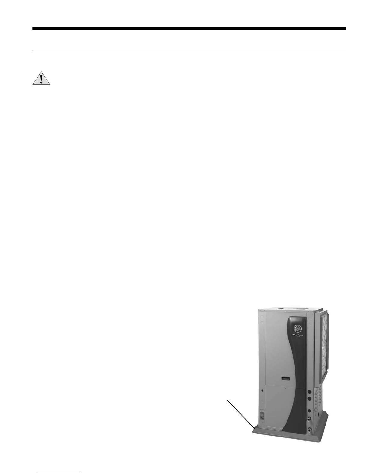
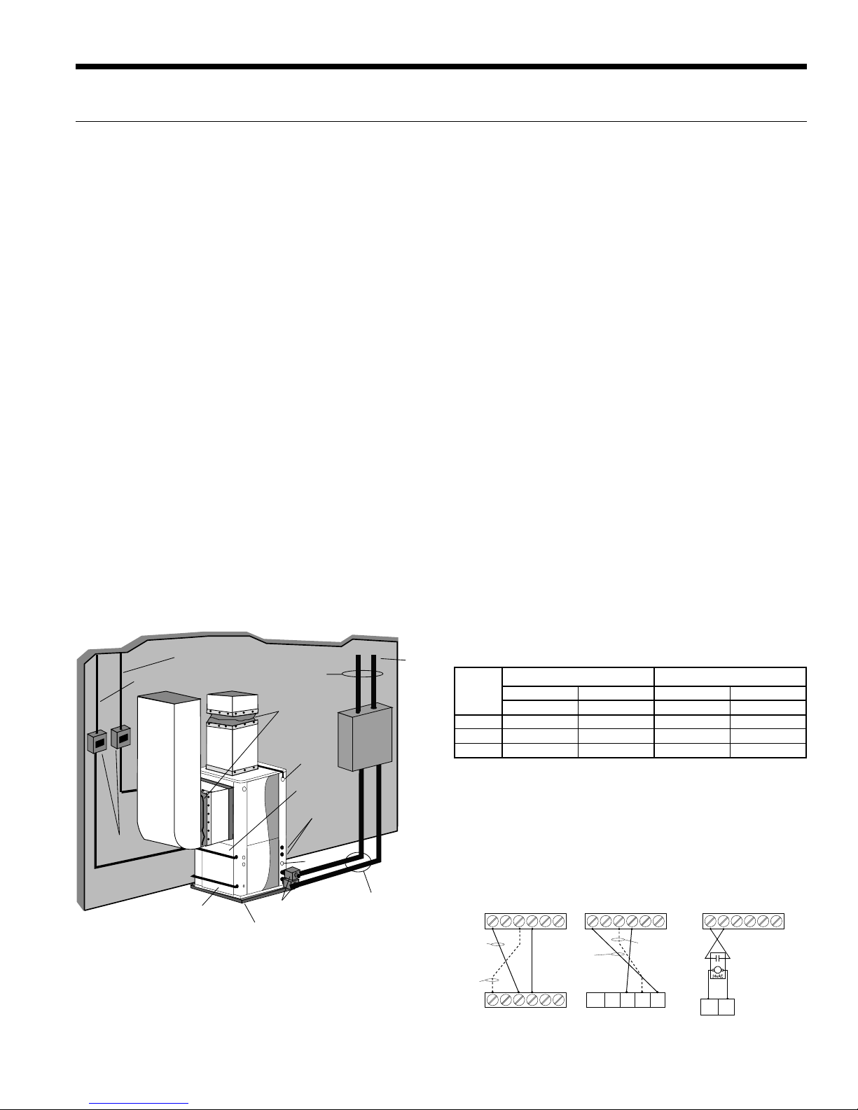
Figure 1: Vertical Unit Mounting
2 in. Extruded
Polystyrene
locate the unit above supply piping. Care should be taken
when units are located in unconditioned spaces to prevent
damage from frozen water lines and excessive heat that
could damage electrical components.
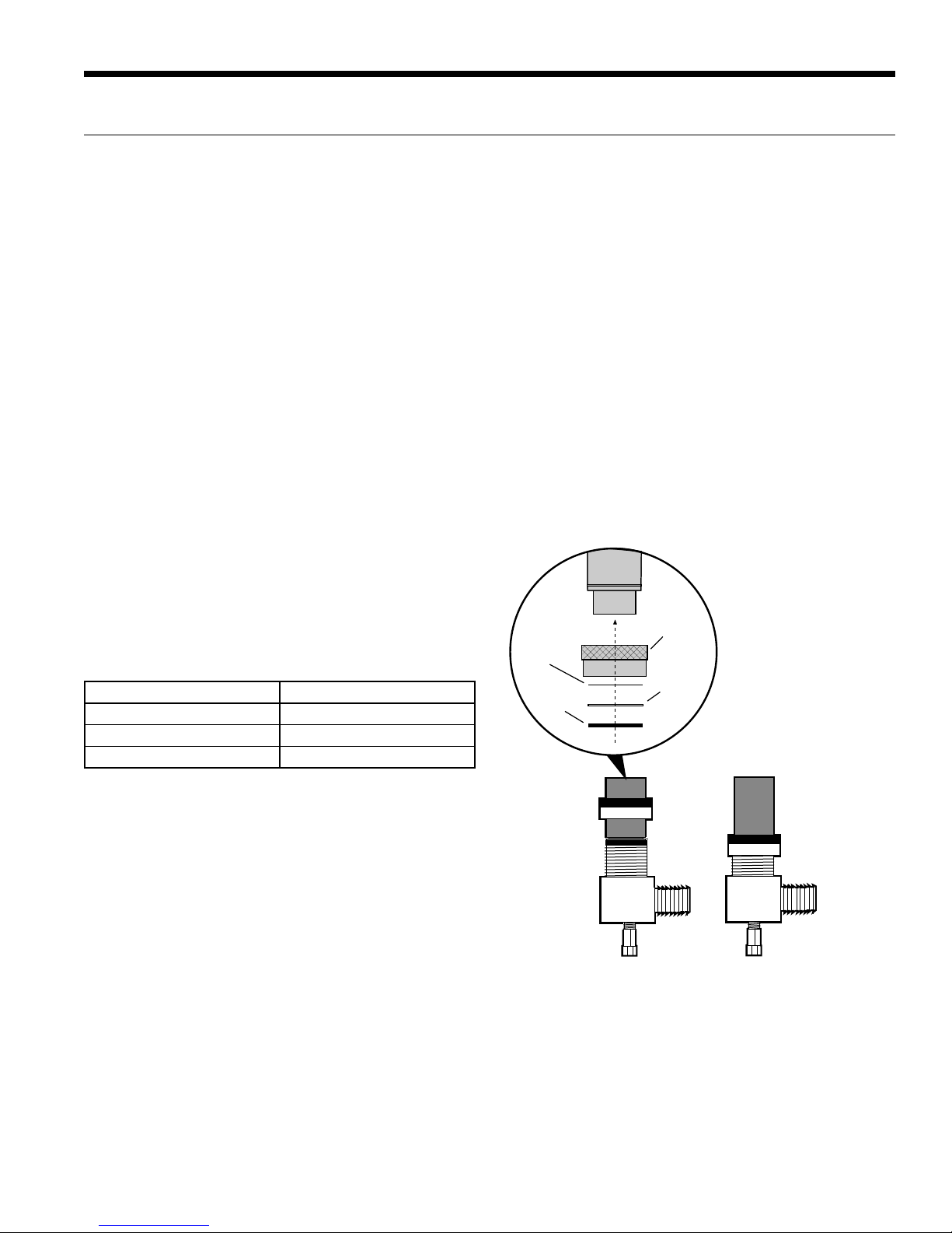
Filter Rack Conversion
A 2 in. MERV 11 filter is shipped with the heat pump. To
field convert the filter rack to use 1 in. filters, simply insert
the provided plastic push pins into the holes located in the
filter rack. There are holes on the top and bottom of the
rack, underneath the instruction labels, for field conversion
to 1 in. filters.
Installing Vertical Units
Prior to setting the unit in place, remove and discard the
compressor hold down shipping bolt located at the front of
the compressor mounting bracket.
Vertical units are available in left or right air return
configurations. Top and rear air discharge vertical units
should be mounted level on a vibration absorbing pad
slightly larger than the base to provide isolation between
the unit and the floor. It is not necessary to anchor the unit
to the floor (see below).
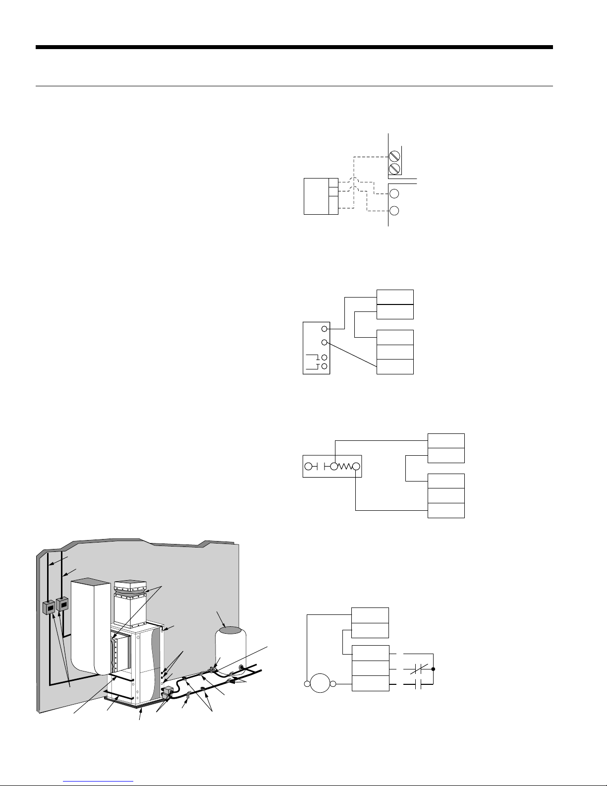
Bottomflow units should be mounted level and sealed well
to floor to prevent air leakage. Bottomflow units require
the supply air opening to be cut at least 1/2 in. larger than
the unit’s air outlet. Protect the edges of combustible
flooring with sheet metal over-wrap or other non-
combustible material.

6
7 SERIES 700A11 INSTALLATION MANUAL
CAUTION: Do not use rods smaller than 3/8-inch
diameter since they may not be strong enough
to support the unit. The rods must be securely
anchored to the ceiling.
General Installation Information cont.
Insulate supply
plenum and use
at least one 90
elbow to
reduce noise
Electrical
Disconnect
Flexible Duct
Collar
Threaded Rods
Line Voltage
Ball Valves
Hose
Kits
To Line
Power
To
Thermostat
Hanging
Brackets
(Included)
Building Water Loop
O
Figure 2: Horizontal Unit Mounting
Installing Horizontal Units
Remove and discard the compressor hold down shipping
bolt located at the front of the compressor mounting
bracket prior to setting the unit in place. Horizontal units
are available with side or end discharge. Horizontal units
are normally suspended from a ceiling by four or six 3/8 in.
diameter threaded rods. The rods are usually attached to
the unit by hanger bracket kits furnished with each unit.
Lay out the threaded rods per the dimensions in Figure
3. Assemble the hangers to the unit as shown. Securely
tighten the brackets to the unit using the weld nuts located
on the underside of the bottom panel. When attaching the
hanger rods to the bracket, a double nut is required since
vibration could loosen a single nut. To allow filter access,
one bracket on the filter side should be installed 180° from
the position shown in Figure 3. The unit should be pitched
approximately 1/4-inch towards the drain in both directions
to facilitate the removal of condensate. Use only the bolts
provided in the kit to attach hanger brackets. The use of
longer bolts could damage internal parts.
Some residential applications require the installation of
horizontal units on an attic floor. In this case, the unit
should be set in a full size secondary drain pan on top of a
vibration absorbing pad. The secondary drain pan prevents
possible condensate overflow or water leakage damage to
the ceiling. The secondary drain pan is usually placed on a
plywood base isolated from the ceiling joists by additional
layers of vibration absorbing material.
SPECIAL NOTE: The VS drive is limited to a maximum of
125°F ambient temperature. For this reason the 7 Series
is not approved for attic installations. The compressor
compartment temperature is also monitored by the
Aurora. This ‘compressor ambient’ temperature is available
on the AID Tool for reading. The control will de-rate the
compressor when ambient air is above 125°F. Installing this
product in an attic could result in loss of warranty.
:STb@WUVb
!&BV`SORSR
@]RPg]bVS`a
6Sf<cba
Pg]bVS`a
EOaVS`
DWP`ObW]\
7a]ZOb]`
0]ZbO\R
:]QYEOaVS`
1
4/
/W`1]WZ
2
0
/W`1]WZ
!
"
"
!
Hanger Dimensions
Model Hanger Kit Part
Number
Unit Hanger Dimensions
ABCD
036 in. 99S500A03 77.4 27.8 24.1 29.3
cm. 196.6 70.6 61.2 74.4
048 in. 99S500A03 77.4 27.8 24.1 29.3
cm. 196.6 70.6 61.2 74.4
060 in. 99S500A03 82.4 27.8 24.1 29.3
cm. 209.3 70.6 61.2 74.4
6/1/12
Weight Distribution
Model
Vertical
Shipping
Weight
Horizontal
Shipping
Weight
Horizontal Weight Distribution
Front Back
1234
036 352 387 135838683
048 361 396 145 84 84 83
060 385 415 120 120 45 130
Weights are listed in lbs. [kg] 6/1/12
Figure 3: Hanger Location and Assembly

7
7 SERIES 700A11 INSTALLATION MANUAL
or compound. Check to ensure that the rubber seal is in
the swivel connector prior to attempting any connection.
The rubber seals are shipped attached to the waterline.
To make the connection to a ground loop system, mate
the brass connector (supplied in CK4LI connector kit)
against the rubber gasket in the swivel connector and
thread the female locking ring onto the pipe threads, while
maintaining the brass connector in the desired direction.
Tighten the connectors by hand, then gently snug the
fitting with pliers to provide a leak-proof joint. When
connecting to an open loop (ground water) system, thread
any 1-inch MPT fitting (SCH80 PVC or copper) into the
swivel connector and tighten in the same manner as noted
above. The open and closed loop piping system should
include pressure/temperature taps for serviceability.
Never use flexible hoses smaller than 1-inch inside diameter
on the unit. Limit hose length to 10 feet per connection.
Check carefully for water leaks.
Duct System
An air outlet collar is provided on vertical top and rear
air discharge units and all horizontal units to facilitate
a duct connection (vertical bottomflow units have no
collar). A flexible connector is recommended for discharge
and return air duct connections on metal duct systems.
Uninsulated duct should be insulated with a minimum of
1-inch duct insulation. Application of the unit to uninsulated
ductwork in an unconditioned space is not recommended
as the unit’s performance will be adversely affected.
If the unit is connected to existing ductwork, check
the duct system to ensure that it has the capacity to
accommodate the air required for the unit application. If
the duct is too small, as in the replacement of heating only
systems, larger ductwork should be installed. All existing
ductwork should be checked for leaks and repaired if
necessary.
The duct system should be sized according to the table
below to handle the design airflow quietly and efficiently.
To maximize sound attenuation of the unit blower, the
supply and return plenums should include an internal duct
liner of fiberglass or constructed of ductboard for the first
few feet. On systems employing a sheet metal duct system,
canvas connectors should be used between the unit and
the ductwork. If air noise or excessive airflow is a problem,
the blower speed can be changed.
Model Design Airflow
NV036 1500
NV048 1800
NV060 2100
Water Piping
The proper water flow must be provided to each unit
whenever the unit operates. To assure proper flow, use
pressure/temperature ports to determine the flow rate.
These ports should be located at the supply and return
water connections on the unit. The proper flow rate cannot
be accurately set without measuring the water pressure
drop through the refrigerant-to-water heat exchanger.
All source water connections on residential units are swivel
piping fittings (see Figure 4) that accept a 1-inch male pipe
thread (MPT). The swivel connector has a rubber gasket
seal similar to a rubber hose gasket, which when mated
to the flush end of any 1-inch threaded pipe provides a
leak-free seal without the need for thread sealing tape
Figure 4: Swivel Connections
Locking
Ring
Stainless
Steel
Snap Ring
Gasket
Support
Sleeve
Gasket
Material
General Installation Information cont.

8
7 SERIES 700A11 INSTALLATION MANUAL
1/2'' Pitch
Drain
1.5 in. 1.5 in.
PVC tube stub
PVC coupling Vent (if needed)
PVC tube stub
1/8 in. per foot
NOTE: Check dimensional data for actual PVC sizes.
Figure 6: Unit Pitch for Drain
Figure 5: Horizontal Drain Connection
Low Water Coil Limit
Set the freeze sensing switch SW2-1 on the Aurora Base
Control (ABC) printed circuit board for applications using
a closed loop antifreeze solution to “LOOP” (15°F). On
applications using an open loop/ground water system (or
closed loop no antifreeze), set this dip switch to “WELL”
(30°F), the factory default setting. (Refer to the DIP Switch
Settings table in the Aurora Control section.)
Condensate Drain
On vertical units, the internal condensate drain assembly
consists of a drain tube which is connected to the
drain pan, a 3/4-inch PVC female adapter and a flexible
connecting hose. The female adapter may exit either the
front or the side of the cabinet. The adapter should be
glued to the field-installed PVC condensate piping. On
vertical units, a condensate hose is inside all cabinets as a
trapping loop; therefore, an external trap is not necessary.
On horizontal units, a PVC stub is provided for condensate
drain piping connection. An external trap is required (see
below). If a vent is necessary, an open stand pipe may be
applied to a tee in the field-installed condensate piping.
Water Quality
In ground water situations where scaling could be heavy
or where biological growth such as iron bacteria will be
present, a closed loop system is recommended. The heat
exchanger coils in ground water systems may, over a period
of time, lose heat exchange capabilities due to a buildup
of mineral deposits inside. These can be cleaned, but only
by a qualified service mechanic, as special solutions and
pumping equipment are required. Hot water generator coils
can likewise become scaled and possibly plugged. In areas
with extremely hard water, the owner should be informed
that the heat exchanger may require occasional flushing.
Units with cupronickel heat exchangers are recommended
for open loop applications due to the increased resistance
to build-up and corrosion, along with reduced wear caused
by acid cleaning. Failure to adhere to the guidelines in the
water quality table could result in the loss of warranty.
General Installation Information cont.
Material Copper 90/10 Cupronickel 316 Stainless Steel
pH Acidity/Alkalinity 7 - 9 7 - 9 7 - 9
Scaling Calcium and
Magnesium Carbonate
(Total Hardness)
less than 350 ppm
(Total Hardness)
less than 350 ppm
(Total Hardness)
less than 350 ppm
Corrosion
Hydrogen Sulfide Less than 0.5 ppm (rotten egg
smell appears at 0.5 ppm) 10 - 50 ppm Less than 1 ppm
Sulfates Less than 125 ppm Less than 125 ppm Less than 200 ppm
Chlorine Less than 0.5 ppm Less than 0.5 ppm Less than 0.5 ppm
Chlorides Less than 20 ppm Less than 125 ppm Less than 300 ppm
Carbon Dioxide Less than 50 ppm 10 - 50 ppm 10 - 50 ppm
Ammonia Less than 2 ppm Less than 2 ppm Less than 20 ppm
Ammonia Chloride Less than 0.5 ppm Less than 0.5 ppm Less than 0.5 ppm
Ammonia Nitrate Less than 0.5 ppm Less than 0.5 ppm Less than 0.5 ppm
Ammonia Hydroxide Less than 0.5 ppm Less than 0.5 ppm Less than 0.5 ppm
Ammonia Sulfate Less than 0.5 ppm Less than 0.5 ppm Less than 0.5 ppm
Total Dissolved Solids (TDS) Less than 1000 ppm 1000 - 1500 ppm 1000 - 1500 ppm
LSI Index +0.5 to -0.5 +0.5 to -0.5 +0.5 to -0.5
Iron Fouling
(Biological Growth)
Iron, FE2+ (Ferrous)
Bacterial Iron Potential < 0.2 ppm < 0.2 ppm < 0.2 ppm
Iron Oxide Less than 1 ppm, above this
level deposition will occur
Less than 1 ppm, above this
level deposition will occur
Less than 1 ppm, above this
level deposition will occur
Erosion
Suspended Solids Less than 10 ppm and filtered
for max. of 600 micron size
Less than 10 ppm and filtered
for max. of 600 micron size
Less than 10 ppm and filtered
for max. of 600 micron size
Threshold Velocity
(Fresh Water) < 6 ft/sec < 6 ft/sec < 6 ft/sec
NOTES: Grains = ppm divided by 17
mg/L is equivalent to ppm
2/22/12

9
7 SERIES 700A11 INSTALLATION MANUAL
Figure 7: Closed Loop Ground Source Application
NOTE: For closed loop systems with antifreeze protection,
set SW2-1 to the “LOOP” (15°F) position. (Refer to the DIP
Switch Settings table in the Aurora Control section.)
Once piping is completed between the unit, pumps and the
ground loop (see figure below), final purging and charging
of the loop is required. A flush cart (or a 1.5 HP pump
minimum) is needed to achieve adequate flow velocity
in the loop to purge air and dirt particles from the loop
itself. Antifreeze solution is used in most areas to prevent
freezing. Flush the system adequately to remove as much
air as possible then pressurize the loop to a static pressure
of 40-50 psi (summer) or 50-75 psi (winter). This is
normally adequate for good system operation. Loop static
pressure will fluctuate with the seasons. Pressures will be
higher in the winter months than during the cooling season.
This fluctuation is normal and should be considered when
initially charging the system.
After pressurization, be sure to turn the venting (burping)
screw in the center of the pump two (2) turns open (water
will drip out), wait until all air is purged from the pump,
then tighten the plug. Variable speed pumps do not have
a venting screw. Ensure that the loop pumps provide
adequate flow through the unit(s) by checking the pressure
drop across the heat exchanger and comparing it to the unit
capacity data in this catalog. 2.5 to 3 gpm of flow per ton of
cooling capacity is recommended in earth loop applications.
Flexible Duct
Collar
Vibration Absorbing Pad
P/T Plugs
Drain
Hot Water Generator
Connections
Auxiliary
Heater
Knockout
Low
Voltage to
Thermostat
Unit Supply
Auxiliary Heat
Supply
Insulated piping
or hose kit
Disconnects
(If Applicable)
Unit Power
P/T
TO
LOOP
GeoLink
®
Flow
Center
GeoLink®
Polyethylene w/
Armaflex®
Insulation
NOTE: Additional information can be found in Flow
Center installation manual and Flush Cart manual.
Closed Loop Ground Source Systems
Figure 8: Primary/Secondary Hook-up
7 Series to
Electromechanical Units
7 Series to
Envision Units
7 Series Unit #1
with AXB Board
7 Series Unit #1
with AXB Board
7 Series Unit #1
with AXB Board
7 Series to
5 or 7 Series Units
CS
With pump
wired to
Unit 2
With pump
wired to Unit 1 With pump
wired to
Unit 1
With pump
wired to
Unit 2
Shut
Down CC
SL1
In SL1
Out
VSPUMPSLAVEOUTIN C C 12 VSPUMPSLAVEOUTIN C C 12 VSPUMPSLAVEOUTIN C C 12
VSPUMPSLAVEOUTIN C C 12
Multiple Units on One Flow Center
NOTE: This feature is only available in the Aurora Advanced
Control package (AXB board), NOT the Aurora Base
Control (ABC).
When two units are connected to one loop pumping system,
pump control is automatically achieved by connecting the
SL terminals on connector P2 in both units with 2-wire
thermostat wire. These terminals are polarity dependant (see
Figure 8). The loop pump(s) may be powered from either
unit, whichever is more convenient. If either unit calls, the loop
pump(s) will automatically start. The use of two units on one
flow center is generally limited to a total of 20 gpm capacity.
Variable Speed Pump Setup
When using a variable speed pump flow center (FCV1-GL,
FCV2-GL, FCV1-GLNP, or FCV2-GLNP) the use of an AID
Tool will be necessary to adjust minimum and maximum
flow rates. The factory default is: minimum=50% and
maximum=100% speed levels. See the 7 Series Variable
Speed Pump Setup and Modulating Water Valve Setup
instructions within the Unit Startup section which is located
in the back of this manual. Always ensure that there is
adequate flow for the heat pump. See Recommended
Minimum/Maximum Flow Rates table.
NOTE: When sharing a flow center, the variable speed heat
pump should be the primary unit. When two variable speed
heat pumps share a flow center, the larger capacity heat
pump should be the primary unit.
Recommended Minimum/Maximum Flow Rates
Model
and Size
Closed Loop Open Loop
Min. Flow Rate Max. Flow Rate Min. Flow Rate Max. Flow Rate
GPM GPM GPM GPM
NV*036 5.0 12.0 5.0 8.0
NV*048 5.0 15.0 5.0 10.0
NV*060 5.0 18.0 5.0 12.0
6/7/12

10
7 SERIES 700A11 INSTALLATION MANUAL
Typical open loop piping is shown below. Always maintain
water pressure in the heat exchanger by placing water
control valves at the outlet of the unit to prevent mineral
precipitation. Use a closed, bladder-type expansion tank
to minimize mineral formation due to air exposure. Ensure
proper water flow through the unit by checking pressure
drop across the heat exchanger and comparing it to the
figures in unit capacity data tables in the specification
catalog. 1.5-2 gpm of flow per ton of cooling capacity is
recommended in open loop applications.
Discharge water from the unit is not contaminated in any
manner and can be disposed of in various ways, depending
on local codes, i.e. recharge well, storm sewer, drain field,
adjacent stream or pond, etc. Most local codes forbid the use
of sanitary sewer for disposal. Consult your local building and
zoning departments to assure compliance in your area. On
VS systems, a modulating valve, as shown in figure 9a is the
best choice to limit water consumption. The WWKVS well
water kit with modulating valve is the recommended setup
for open loop applications with variable speed products.
NOTE: For open loop/groundwater systems or systems
that do not contain an antifreeze solution, set SW2-Switch
#1 to the “WELL” (30°F) position. (Refer to the DIP Switch
Settings in the Aurora Control section.) Slow opening/
closing solenoid valves (type VM or V) or modulating
valves are recommended to eliminate water hammer.
Modulating Water Valve Setup
When using a modulating water valve (23P529-01) the use
of an AID Tool will be necessary to adjust minimum and
maximum flow rates. The factory default is: minimum=50%
and maximum=100% flow levels. See the 7 Series Variable
Speed Pump Setup and Modulating Water Valve Setup
instructions within the Unit Startup section which is located
in the back of this manual. See Recommended Minimum
and Maximum Flow Rates table. Always ensure that there is
adequate flow for the heat pump. A modulating water valve
is preferred on variable speed system to conserve water.
Figure 9c: Open Loop Solenoid Valve Connection Option
Typical slow operating external 24V water solenoid valve
(type VM) wiring.
Figure 9d: Open Loop Solenoid Valve Connection Option
Typical quick operating external 24V water solenoid valve
(type PPV100 or BPV100) wiring.
Flexible
Duct Collar
Vibration
Absorbing Pad
P/T Plugs
Drain
Hot Water Generator
Connections
Auxiliary
Heater
Knockout
Low Voltage
to Thermostat
and Valve
Unit Supply
Aux. Heat Supply
Water Out
Water In
Shut Off Valves
Boiler Drains
For HX Flushing
Disconnects
(IfApplicable)
Rubber Bladder
Expansion Tank
Solenoid
Valve
Shut Off Valves
(to isolate solenoid
valve while acid flushing)
Strainer
Flow Control
Valve
(on outlet of
Solenoid Valve)
Compressor
Line Voltage
Figure 10: Open System - Groundwater Application
NOTE: SW2-4 and SW2-5 should be “OFF” to cycle with the compressor.
Open Loop Ground Water Systems
Acc Com
Acc NC
Acc NO
1
2
3
C
RP1
P2
SV
Solenoid
Valve
ABC Board
NOTE: SW2-4 should be “ON” and SW2-5 should be “OFF” when using
a slow opening (VM or V) water valve.
Figure 9a: Modulating Water Valve Connection Option
Typical 0-10VDC modulating water valve.
VS PUMP
GND
24 VAC
0-10DC
1
2
3R
C
ABC BOARD
AXB BOARD
2 1
VALVE
Figure 9b: Open Loop Solenoid Valve Connection Option
Typical slow operating external 24V water solenoid valve
(type V) wiring.
C
R
Acc Com
ACC NC
Acc NO
C
W/Y
V Valve ABC Board
C
R
Acc Com
ACC NC
Acc NO
VM Valve
ABC Board

11
7 SERIES 700A11 INSTALLATION MANUAL
To maximize the benefits of the hot water generator a
minimum 50-gallon water heater is recommended for
higher demand applications, use an 80-gallon water
heater or two 50-gallon water heaters connected in a
series as shown below. Two tanks plumbed in a series
is recommended to maximize the hot water generator
capability. Electric water heaters are recommended. Make
sure all local electrical and plumbing codes are met for
installing a hot water generator. Residential units with hot
water generators contain an internal circulator and fittings.
A water softener is recommended with hard water (greater
than 10 grains or 170 total hardness).
NOTES: 1) Using a preheat tank, as shown in Figure 12, will
maximize hot water generator capabilities. 2) The hot water
generator coil is constructed of vented double wall copper
suitable for potable water.
Figure 11: Typical Hot Water Generator Installation
CAUTION: Elements will burn out if energized dry.
Figure 12: Hot Water Generator Installation In Preheat Tank
In
Venting Waste Valve
or Vent Coupling
3/4" x 3/4"
x 1/2" tee Cold
Water In
Hot
Water Out
P/T Relief
Valve
P/T Relief
Valve
HWG
Water In
HWG
Water Out
Drain ValveDrain Valve
Storage
Tank
Electric Powered
Water Heater
Water Tank Preparation
To install a unit with a hot water generator, follow these
installation guidelines.
1. Turn off the power to the water heater.
2. Attach a water hose to the water tank drain
connection and run the other end of the hose to an open
drain or outdoors.
3. Close the cold water inlet valve to the water heater tank.
4. Drain the tank by opening the valve on the bottom
of the tank, then open the pressure relief valve or hot
water faucet.
5. Flush the tank by opening the cold water inlet valve to
the water heater to free the tank of sediments. Close
when draining water is clear.
6. Disconnect the garden hose and remove the drain valve
from the water heater.
7. Refer to Plumbing Installation and Hot Water
Generator Startup.
NOTE: This configuration maximizes hot water
generator capability.
DrainValve
In
P/TRelief
Valve
Cold
Water In Hot
Water Out
HWG
Water In
HWG
Water Out
Venting Waste
Valve or Vent
Coupling
3/4” x 3/4” x 1/2” tee
Hot Water Generator Connections

12
7 SERIES 700A11 INSTALLATION MANUAL
Hot Water Generator Startup
1. Turn the hot water generator switch to the “ON”
position. The hot water generator switch will allow the
hot water generator pump to be enabled or disabled by
the service technician or homeowner.
2. Close the drain valve to the water heater.
3. Open the cold water supply to the tank.
4. Open a hot water faucet in the building to bleed air from
the system. Close when full.
5. Open the pressure relief valve to bleed any remaining air
from the tank, then close.
6. If so equipped, turn the venting (burping) screw in the
center of the pump two (2) turns open (water will drip
out), wait until all air is purged from the pump, then
tighten the plug. Use vent couplings to bleed air from
the lines.
7. Carefully inspect all plumbing for water leaks and
correct as required.
8. Before restoring electrical supply to the water heater,
adjust the temperature setting on the tank.
• On tanks with both upper and lower elements,
the lower element should be turned down to
the lowest setting, approximately 100°F. The
upper element should be adjusted to 120°F to
130°F. Depending upon the specific needs of
the customer, you may want to adjust the upper
element differently.
• On tanks with a single element, lower the
thermostat setting to 120°F.
9. After the thermostat(s) is adjusted, replace the access
cover and restore electrical supply to the water heater.
10.Make sure that any valves in the hot water generator
water circulating circuit are open.
11. Use an AID Tool to enable HWG and select the desired
water heating set point. Selectable set points are 100°F
– 140°F in 5°F increments (default 130°F). From the Main
Menu of the AID Tool select Setup, then AXB Setup.
12. Turn on the unit to first stage heating..
13. The hot water generator pump should be running. When
the pump is first started, turn the venting (burping)
screw (if equipped) in the center of the pump two (2)
turns open until water dribbles out, then replace. Allow
the pump to run for at least five minutes to ensure that
water has filled the circulator properly. Be sure the
switch for the hot water generator pump is “ON”.
14. Allow the unit to heat water for 15 to 20 minutes to be
sure operation is normal.
Plumbing Installation
1. Inspect the dip tube in the water heater cold inlet
for a check valve. If a check valve is present it must
be removed or damage to the hot water generator
circulator will occur.
2. Remove drain valve and fitting.
3. Thread the 3/4-inch NPT x 3-1/2-inch brass nipple into
the water heater drain port.
4. Attach the center port of the 3/4-inch FPT tee to the
opposite end of the brass nipple.
5. Attach the 1/2-inch copper to 3/4-inch NPT adaptor to
the side of the tee closest to the unit.
6. Install the drain valve on the tee opposite the adaptor.
7. Run interconnecting tubing from the tee to hot water
generator water out.
8. Cut the cold water “IN” line going to the water heater.
9. Insert the reducing solder tee in line with cold water “IN”
line as shown.
10.
Run interconnecting copper tubing between the unit hot
water generator water “IN” and the tee (1/2-inch nominal).
The recommended maximum distance is 50 feet.
11.
To prevent air entrapment in the system, install a vent
coupling at the highest point of the interconnecting lines.
12. Insulate all exposed surfaces of both connecting water
lines with 3/8-inch wall closed cell insulation.
NOTE: All plumbing and piping connections must comply
with local plumbing codes.
CAUTION: Never operate the HWG circulating
pump while dry. If the unit is placed in operation
before the hot water generator piping is
connected, be sure that the pump switch is set
to the OFF position.
Hot Water Generator Connections cont.
Hot Water Generator Switch
The hot water generator switch is taped in the disabled
position at the factory.

13
7 SERIES 700A11 INSTALLATION MANUAL
General
Be sure the available power is the same voltage and phase
as that shown on the unit serial plate. Line and low voltage
wiring must be done in accordance with local codes or
the National Electric Code, whichever is applicable. The
compressor has no internal overload. The circuit breaker in
the control box is the overload protection for the drive and
the compressor. Bypassing the circuit breaker could result
in damage to the compressor and voiding the warranty.
Unit Power Connection
Connect the incoming line voltage wires to L1 and L2 of
the contactor as shown in Figure 13c for single-phase unit.
Consult the Unit Electrical Data in this manual for correct
fuse sizes.
Open lower front access panel. Remove ground fastener
from bottom of control box (Figure 13b). Swing open
control box (Figure 13a). Insert power wires through
knockouts on lower left side of cabinet. Route wires
through left side of control box and connect to contactor
and ground (Figure 13c). Close control box and replace
grounding fastener before unit startup.
Ground Fastener
must be installed for
proper unit ground
Wire Insert
Location
Figure 13c:
Line Voltage 208-230/60/1 control box
Figure 13b:
Wire access (control box closed)
Figure 13a:
Wire access (control box open)
Electrical Connections
Accessory Relay
A set of “dry” contacts has been provided to control
accessory devices, such as water solenoid valves on open
loop installations, electronic air cleaners, humidifiers, etc.
This relay contact should be used only with 24 volt signals
and not line voltage power. The relay has both normally
open and normally closed contacts and can operate with
either the blower or the compressor. Use DIP switch SW2-4
and 5 to cycle the relay with blower, compressor, or control
a slow opening water valve. The relay contacts are available
on terminals #2 and #3 of P2.
A second configurable accessory relay is provided on the
AXB board. When powering high VA draw components
such as electronic air cleaners or VM type open loop water
valves, R should be taken ‘pre-fuse’ from the ‘R’ quick
connect on the ABC board and not the ‘post-fuse’ ‘R’
terminal on the thermostat connection. If not, blown ABC
fuses might result.
208 Volt Operation
All 208/230 units are factory wired for 230 volt operation.
For 208 volt operation, the red and blue transformer wires
must be switched on terminal strip PS.
L1
L2
PB1
CB
L1
L2
Compressor
Drive
Overload
CAUTION: Frequent cycling of power to the drive
can damage the drive! Wait at least 5 minutes
between cycles (connecting and disconnecting
power to the drive).

14
7 SERIES 700A11 INSTALLATION MANUAL
Electrical Connections cont.
Electronic Thermostat Installation
Position the thermostat subbase against the wall so that
it is level and the thermostat wires protrude through
the middle of the subbase. Mark the position of the
subbase mounting holes and drill holes with a 3/16-inch
bit. Install supplied anchors and secure base to the wall.
Thermostat wire must be 4-conductor, 20-AWG (minimum)
wire. Strip the wires back 1/4-inch (longer strip lengths
may cause shorts) and insert the thermostat wires into
the connector as shown. Tighten the screws to ensure
secure connections. The thermostat has the same type
connectors, requiring the same wiring. See instructions
enclosed in the thermostat for detailed installation and
operation information. The W1 terminal on TPCM32U04
communicating thermostats may be hard wired to provide
aux/emergency heat in the event communication is lost
between the thermostat and the ABC microprocessor.
C
P7
P1
–
R
W
C 24VAC (Common)
R 24VAC (Hot)
B- Communication
W1 (Optional)
ABC Controller
Thermostat Connection
+A+ Communication
TPCM32U04
Monochrome Thermostats
C
P7
–
R
C 24VAC (Common)
R 24VAC (Hot)
DX- Communication
ABC
Controller
Thermostat
Connection
+DX+ Communication
TPCC32U01
Color Touchscreen
Thermostat
Figure 15: Thermostat Wiring (Communicating Style Signals)
Pump Power Wiring
See Figure 14 for electrical connections from control box
to pumps.
FC1/FC2 style flow centers with fixed speed pumps
connect to PB1 in the control box. If using a variable speed
pump it should be connected to L1 and L2 on the AXB.
Figure 14: Pump Wiring 208-230/60/1
External Loop Pump(s)
(ex. UP26-99)
208-230/60/1
1/2 hp Max
(Optional)
External Variable
Speed Loop Pump
(ex. Magna Geo)
208-230/60/1
L1
L2
PB1
CB
NOTE: If using the IntelliZone2 zoning system, then
disregard the diagrams above. The IntelliZone2 system will
connect directly to the AXB control board instead. See the
IntelliZone2 installation manual for more details.

15
7 SERIES 700A11 INSTALLATION MANUAL
Model
kW
Stages
Btu/h
Min CFM
Model Compatibility
208V 230V 208V 230V 036 048 060
EAL(H)10 7.2 9.6 2 24,600 32,700 1100 • • •
EAL(H)15 10.8 14.4 3 36,900 49,100 1250 • • •
EAL(H)20 14.4 19.2 4 49,200 65,500 1500 • •
Air flow level for auxiliary heat (Aux) must be above the minimum cfm in this table
Order the “H” part number when installed on horizontal and vertical rear discharge units
6/1/12
Model Supply
Circuit
Heater Amps Min Circuit Amp Max Fuse (USA) Max Fuse (CAN) Max CKT BRK
208 V 240 V 208 V 240 V 208 V 240 V 208 V 240 V 208 V 240 V
EAL(H)10 Single 34.7 40 53.3 60 60 60 60 60 60 60
EAL(H)15
Single 52.0 60 75 85 80 90 80 90 70 100
L1/L2 34.7 40 53.3 60 60 60 60 60 60 60
L3/L4 17.3 20 21.7 25 25 25 25 25 20 30
EAL(H)20
Single 69.3 80 96.7 110 100 110 100 110 100 100
L1/L2 34.7 40 53.3 60 60 60 60 60 60 60
L3/L4 34.7 40 43.3 50 45 50 45 50 40 50
All heaters rated single phase 60 cycle and include unit fan load
All fuses type “D” time delay (or HACR circuit breaker in USA)
6/1/12
Model Rated
Voltage
Voltage
Min/Max
Compressor Drive HWG
Pump
FLA
Ext Loop
FLA
Blower
Motor
FLA
Total Unit
FLA
Minimum
Circuit
Amp
Max Fuse
HACR
Breaker
LRA CMCC LRA Internal
Breaker
036 208-230/60/1 187/253 10.2 18.0 22.0 30.0 0.4 5.4 4.0 31.8 37.3 40
*036 208-230/60/1 187/253 10.2 18.0 22.0 30.0 0.4 5.4 7.0 34.8 40.3 45
048 208-230/60/1 187/253 12.0 23.5 28.0 35.0 0.4 5.4 7.0 40.8 47.8 50
060 208-230/60/1 187/253 12.0 30.0 33.0 40.0 0.4 5.4 7.0 45.8 54.1 60
*With optional 1 hp Variable Speed ECM Motor
Rated Voltage of 208/230/60/1
HACR circuit breaker in USA only
All fuses Class RK-5
3/26/12
Auxiliary Heat Ratings
Auxiliary Heat Electrical Data
Electrical Data

16
7 SERIES 700A11 INSTALLATION MANUAL
ECM Speed Info
1
▶2◀G
3
4
5
6
7
8
9
10
11
12
Option ◀▶ Enter ◙
ECM Speed Info
1
2G
▶3◀Lo
4
5
6
7
8
9
10
11
12
Option ◀▶ Enter ◙
ECM Speed Info
1
2G
3Lo
4
5
▶6◀Hi
7
8
9
10
11
12
Option ◀▶ Enter ◙
ECM Speed Info
1
2G
3Lo
4
5
6Hi
7
8
9
▶10 ◀Aux
11
12
Option ◀▶ Enter ◙
ECM Speed Info
Blower Only Speed 3
Lo Compressor 6
Hi Compressor 9
Aux Heat 10
Want To Change?
Yes
Option ◀▶
No
Enter ◙
Cooling Airflow Setup
--- ECM Only ---
The airflow will be
adjusted by the chosen
amount in cooling mode.
Adjustment:
-15%
Want To Change?
Yes
Option ◀▶
No
Enter ◙
Cooling Airflow Setup
--- ECM Only ---
The airflow will be
adjusted by the chosen
amount in cooling mode.
Adjustment:
-15%
Change ▼▲ Enter ◙
Setting Blower Speed - Variable speed ECM
The ABC board’s Yellow Config LED will flash the current
ECM blower speed selections for G, low, and high
continuously with a short pause in between. The speeds
can also be confirmed with the AID Tool under the Setup/
ECM Setup screen. The Aux will not be flashed but can be
viewed in the AID Tool. The ECM blower motor speeds can
be field adjusted with or without using an AID Tool.
Variable speed ECM Setup without an AID Tool
The blower speeds for G only, Low (Y1), and High (Y2/
Aux) can be adjusted directly at the Aurora ABC board
which utilizes the push button (SW1) on the ABC board.
This procedure is outlined in the ECM Configuration Mode
portion of the Aurora ‘Base’ Control System section. The
Aux cannot be set manually without an AID Tool.
Variable speed ECM Setup with an AID Tool
A much easier method utilizes the AID Tool to change
the airflow using the procedure below. First navigate to
the Setup screen and then select ECM Setup. This screen
displays the current ECM settings. It allows the technician to
enter the setup screens to change the ECM settings. Change
the highlighted item using the ◄
and ►buttons and then press the
◙button to select the item.
Selecting YES will enter ECM
speed setup, while selecting NO
will return to the previous screen.
ECM Speed Setup - These screens allow the technician to
select the G, low, high, and auxiliary heat blower speed for
the ECM blower motor. Change the highlighted item using
the ▲and ▼buttons. Press the ◙button to select the speed.
After the auxiliary heat speed setting is selected the AID
Tool will automatically transfer back to the ECM Setup screen.
Cooling Airflow Setup - These screens allow the technician
to select -15%, -10%, -5%, None or +5% change from the
heating airflow. Change the adjustment percentage using
the ▲and ▼buttons. Press the ◙button to save the change.
Variable Speed ECM Blower Motor
Model
Air Flow
Max
ESP
Speed
1
Speed
2
Speed
3
Speed
4
Speed
5
Speed
6
Speed
7
Speed
8
Speed
9
Speed
10
Speed
11
Speed
12
036 0.50 285 380
G
5 2 5
L
675 815 980 1100 1220 1330 1440
H
1540
Aux
1575
036 w/1hp* 0.75 480 565
G
665
L
761 870 1000 1100 1200 1300 1410
H
1520
Aux
1630
048 0.75 475 620
G
7 3 0
L
850 1020 1140 1270 1400 1520 1650
H
1790
Aux
1925
060 0.75 400 600
G
830
L
1050 1230 1400 1560 1700 1870 2010
H
2140
Aux
2265
**VS Compressor Speed 1-2 3-4 5-6 7-8 9-10 11-12
** VS Compressor speed is given for the factory default cfm settings. When the cfm default settings are changed it will change the
relationship to the compressor speed that is shown in the table. In cooling mode compressor speeds 10-12 are only available when
SuperBoost mode is selected at the thermostat.
* Optional 1 hp Variable Speed ECM
Factory settings are at recommended L , H and Aux positions
“G” may be located anywhere within the airflow table
“L” setting should be located within the boldface cfm range
“H” setting MUST be located within the shaded cfm range
“Aux” setting MUST be equal to or greater than “H” setting
“Aux” setting MUST be equal to or greater than the minimum allowable cfm for the auxiliary heater kit (see auxiliary heat ratings table)
Cfm is controlled within 5% up to the maximum ESP
Max ESP includes allowance for wet coil and standard filter
6/7/12
Blower Performance Data

17
7 SERIES 700A11 INSTALLATION MANUAL
LEFT RETURN RIGHT RETURN
FRONT
TOP
2 ft [61 cm]
Primary Service Access
TOP
ADEHFIKJ G
1.9in
[4.8cm]
1.9in
[4.8cm]
M
R
Q
N
O
L
R
N
O
L
PQ
RIGHT SIDE
B
C
B
LEFT SIDE
S
T
S
T
C
Top Air Discharge
Vertical Top
Flow Model
Overall Cabinet Water Connections Electrical
Connections
Discharge Connection
duct flange installed (±0.10 in)
Return Connection
using std deluxe filter rack
(±0.10 in)
A
Width
B
Depth
C
Height
D
Loop
In
E
Loop
Out
F
HWG
In
G
HWG
Out
H
Cond-
ensate
Loop
Water
FPT
HWG
Sweat
(I.D.)
I
1/2 in.
cond
J
1/2 in.
cond
K
3/4 in.
cond LM
N
Supply
Width
O
Supply
Depth
PQ
R
Return
Depth
S
Return
Height
T
Low
Voltage
Ext
Pump
Power
Supply
036 in. 25.6 31.6 54.4 2.3 7.3 15.9 18.9 10.6 1 in.
Swivel
1/2 in.
Female
14.3 9.8 12.3 6.9 1.1 18.0 18.0 3.8 1.7 28.1 30.0 1.7
cm. 65.0 80.3 138.2 5.8 18.5 40.4 48.0 26.9 36.3 24.9 31.2 17.5 2.8 45.7 45.7 9.7 4.3 71.4 76.2 4.3
048 in. 25.6 31.6 54.4 2.3 7.3 15.9 18.9 10.6 1 in.
Swivel
1/2 in.
Female
14.3 9.8 12.3 6.9 1.1 18.0 18.0 3.8 1.7 28.1 30.0 1.7
cm. 65.0 80.3 138.2 5.8 18.5 40.4 48.0 26.9 36.3 24.9 31.2 17.5 2.8 45.7 45.7 9.7 4.3 71.4 76.2 4.3
060 in. 25.6 31.6 58.4 2.3 7.3 15.9 18.9 10.6 1 in.
Swivel
1/2 in.
Female
14.3 9.8 12.3 6.9 1.1 18.0 18.0 3.8 1.7 28.1 34.0 1.7
cm. 65.0 80.3 148.3 5.8 18.5 40.4 48.0 26.9 36.3 24.9 31.2 17.5 2.8 45.7 45.7 9.7 4.3 71.4 86.4 4.3
Condensate is 3/4 in. PVC female glue socket and is switchable from side to front
Unit shipped with deluxe 2 in. (field adjustable to 1 in.) duct collar/filter rack extending from unit 3.25 in. and is suitable for duct connection.
Discharge flange is field installed and extends 1 in. [25.4mm] from cabinet
Decorative molding and/or water connections extend 1.2 in. [30.5mm] beyond front of cabinet.
Louvered vents in the compressor section right side access panel extend 1/2 in. [12.7 mm] from side of cabinet. Allow clearance for venting.
6/29/12
Vertical Dimensional Data

18
7 SERIES 700A11 INSTALLATION MANUAL
2 ft [61 cm]
Primary Service Access
LEFT SIDE RIGHT SIDE
B
C
S
T T
B
C
S
LEFT RETURN RIGHT RETURN
RQ
LN
O
P
A
FRONT
D
E
FG
H
J
K
I
1.90
(4.7 cm)
1.70
(4.3 cm)
1
2
3
4
5
RIGHT BOTTOM DISCHARGE
FLOOR FOOT PRINT
R
O
N
L
M
LEFT BOTTOM DISCHARGE
FLOOR FOOT PRINT
Q
Bottom Air Discharge
Bottomflow
Models
Overall Cabinet
Water Connections Electrical Knockouts
Discharge Connection
duct flange installed (±0.10 in)
Return Connection
using std deluxe filter rack
(±0.10 in)
12345
Loop
Water
FPT
HWG
Sweat
(I.D.)
I
1/2 in.
cond
J
1/2 in.
cond
K
3/4 in.
cond
A
Width
B
Depth
C
Height
D
In
E
Out
F
HWG
In
G
HWG
Out
H
Cond-
ensate
Low
Voltage
Ext
Pump
Power
Supply
LM
N
Supply
Width
O
Supply
Depth
PQ
R
Return
Depth
S
Return
Height
T
036-
060
in. 25.5 31.5 62.5 43.4 48.4 57.0 60.0 3.1 1 in.
Swivel
1/2 in.
Female
51.1 55.6 53.6 9.1 4.8 13.4 13.6 1.7 1.8 28.1 34.0 5.6
cm. 64.8 80.0 158.8 110.2 122.9 144.8 152.4 7.9 129.8 141.2 136.1 23.1 12.2 34.0 34.5 4.3 4.6 71.4 86.4 14.2
Condensate is 3/4 in. PVC female glue socket and is switchable from side to front
Unit shipped with deluxe 2 in. (field adjustable to 1 in.) duct collar/filter rack extending from unit 3.25 in. and is suitable for duct connection.
Decorative molding and/or water connections extend 1.2 in. [30.5mm] beyond front of cabinet.
Louvered vents in the compressor section right side access panel extend 1/2 in. [12.7 mm] from side of cabinet. Allow clearance for venting.
4/30/12
Vertical Dimensional Data cont.

19
7 SERIES 700A11 INSTALLATION MANUAL
Rear Air Discharge
REAR VIEW
LEFT RETURN
SIDE VIEW
RIGHT RETURN
SIDE VIEW
LEFT RETURN
REAR VIEW
RIGHT RETURN
FRONT
CCCC
AA
A
BB
D
EHFG
J
K
I
L
M
N
M
N
P
OQ
QRR
SS
TT
1.90 in. [4.8 cm]
1.90 in.
[4.8 cm]
2 ft [61 cm]
Primary Service Access
Verti-
cal Rear
Discharge
Model
Overall Cabinet Water Connections Electrical
Connections
Discharge Connection
duct flange installed (±0.10 in)
Return Connection
using std deluxe filter rack
(±0.10 in)
A
Width
B
Depth
C
Height
D
Loop
In
E
Loop
Out
F
HWG
In
G
HWG
Out
H
Cond-
ensate
Loop
Water
FPT
HWG
Sweat
(I.D.)
I
1/2 in.
cond
J
1/2 in.
cond
K
3/4 in.
cond
L
Supply
Width
M
Supply
Depth
NOPQ
R
Return
Depth
S
Return
Height
T
Low
Voltage
Ext
Pump
Power
Supply
036 in. 25.6 31.6 54.4 2.3 7.3 15.9 18.9 10.6 1 in.
Swivel
1/2 in.
Female
14.3 9.8 12.3 13.3 13.6 39.4 9.1 8.1 1.7 28.1 30.0 1.7
cm. 65.0 80.3 138.2 5.8 18.5 40.4 48.0 26.9 36.3 24.9 31.2 33.8 34.5 100.1 23.1 20.6 4.3 71.4 76.2 4.3
048 in. 25.6 31.6 54.4 2.3 7.3 15.9 18.9 10.6 1 in.
Swivel
1/2 in.
Female
14.3 9.8 12.3 13.3 13.6 39.4 9.1 8.1 1.7 28.1 30.0 1.7
cm. 65.0 80.3 138.2 5.8 18.5 40.4 48.0 26.9 36.3 24.9 31.2 33.8 34.5 100.1 23.1 20.6 4.3 71.4 76.2 4.3
060 in. 25.6 31.6 58.4 2.3 7.3 15.9 18.9 10.6 1 in.
Swivel
1/2 in.
Female
14.3 9.8 12.3 13.3 13.6 43.4 9.1 8.1 1.7 28.1 34.0 1.7
cm. 65.0 80.3 148.3 5.8 18.5 40.4 48.0 26.9 36.3 24.9 31.2 33.8 34.5 110.2 23.1 20.6 4.3 71.4 86.4 4.3
Condensate is 3/4 in. PVC female glue socket and is switchable from side to front
Unit shipped with deluxe 2 in. (field adjustable to 1 in.) duct collar/filter rack extending from unit 3.25 in. and is suitable for duct connection.
Discharge flange is field installed and extends 1 in. [25.4mm] from cabinet
Decorative molding and/or water connections extend 1.2 in. [30.5mm] beyond front of cabinet.
Louvered vents in the compressor section right side access panel extend 1/2 in. [12.7 mm] from side of cabinet. Allow clearance for venting.
6/29/12
Vertical Dimensional Data cont.

20
7 SERIES 700A11 INSTALLATION MANUAL
2 ft [61 cm]
Primary Service Access
B
C
2.1in
[5.4cm]
H
L
ON
M
S
R
Q
P
MOUNT (2) HANGER BRACKETS
AS SHOWN TO ALLOW ACCESS
TO FILTER
AS SHOWN LR UNIT (RR UNIT ON OPPOSITE SIDE—SAME DIMENSIONS)
SIDE DISHCARGE VIEW END VIEW
TOP VIEW
A
S
FRONT VIEW
DEFG
IKJ
1.9in
[4.8cm] O
L
Units Not Shown Above L O
Right Return End Discharge in 2.8 4.6
cm 7.1 11.8
Right Return Side Discharge in 4.9 6.9
cm 12.4 17.5
Left Return End Discharge in 4.9 7.6
cm 12.4 19.4
Left Return Side Discharge in 2.8 6.9
cm 7.1 17. 5
Horizontal
Models
Overall Cabinet Water Connections
Electrical Connections
Discharge Connection
duct flange installed (±0.10 in)
Return Connection
using std deluxe filter rack
(±0.10 in)
I
1/2 in.
cond
J
1/2 in.
cond
K
3/4 in.
cond
A
Width
B
Depth
C
Height
D
In
E
Out
F
HWG
In
G
HWG
Out
H
Cond-
ensate
Loop
Water
FPT
HWG
Sweat
(I.D.)
Low
Voltage
Ext
Pump
Power
Supply
L
M
Supply
Height
N
Supply
Depth
OP
Q
Return
Depth
R
Return
Height
S
036 in. 25.6 77.0 21.3 2.3 7.3 15.9 18.9 0.8 1 in.
Swivel
1/2 in.
Female
14.3 9.8 12.3
SEE
CHART
13.6 13.2
SEE
CHART
2.8 40.4 18.9 1.3
cm. 65.0 195.6 54.1 5.8 18.5 40.4 48.0 2.0 36.3 24.9 31.2 34.5 33.5 7.1 102.6 48.0 3.3
048 in. 25.6 77.0 21.3 2.3 7.3 15.9 18.9 0.8 1 in.
Swivel
1/2 in.
Female
14.3 9.8 12.3
SEE
CHART
13.6 13.2
SEE
CHART
2.8 40.4 18.9 1.3
cm. 65.0 195.6 54.1 5.8 18.5 40.4 48.0 2.0 36.3 24.9 31.2 34.5 33.5 7.1 102.6 48.0 3.3
060 in. 25.6 82.0 21.3 2.3 7.3 15.9 18.9 0.8 1 in.
Swivel
1/2 in.
Female
14.3 9.8 12.3
SEE
CHART
13.6 13.2
SEE
CHART
2.8 45.4 18.9 1.3
cm. 65.0 208.3 54.1 5.8 18.5 40.4 48.0 2.0 36.3 24.9 31.2 34.5 33.5 7.1 115.3 48.0 3.3
Condensate is 3/4 in. PVC female glue socket and is switchable from side to front
Unit shipped with deluxe 2 in. (field adjustable to 1 in.) duct collar/filter rack extending from unit 3.25 in. and is suitable for duct connection.
Discharge flange is field installed and extends 1 in. [25.4mm] from cabinet
Decorative molding and/or water connections extend 1.2 in. [30.5mm] beyond front of cabinet.
Louvered vents in the compressor section right side access panel extend 1/2 in. [12.7 mm] from side of cabinet. Allow clearance for venting.
6/29/12
Horizontal Dimensional Data
This manual suits for next models
1
Table of contents
Popular Heat Pump manuals by other brands

Sinclair
Sinclair SMH-100IRA? SMH-140IRA Operation manual

Ochsner
Ochsner EUROPA Mini IWP OPERATING AND INSTALLATION Manual

Sanyo
Sanyo SAP362TCH Service manual

Dantherm
Dantherm calorex PP16AMY Owners & installation manual

York
York E9FD018 Series Installation instruction

Dimplex
Dimplex SI 35TUR Installation and operating instruction