6Waterford E65-1 Emerald Direct Vent Freestanding Gas Stove
IMPORTANT:
SAVE THESE
INSTRUCTIONS
The EMERALD Direct Vent Freestanding Gas
Stove must be installed in accordance with
these instructions. Carefully read all the in-
structionsinthismanualfirst.Consultthebuild-
ingauthorityhavingjurisdictiontodeterminethe
needforapermitpriortostartingtheinstallation.
Note: Failure to follow the instructions
could cause a malfunction of the
heaterwhichcouldresultindeath,
seriousbodilyinjury,and/orprop-
erty damage. Failure to follow
these instructions may also void
your fire insurance and/or war-
ranty.
Note: These instructions take prece-
dence over Simpson Dura-Vent
instructions.
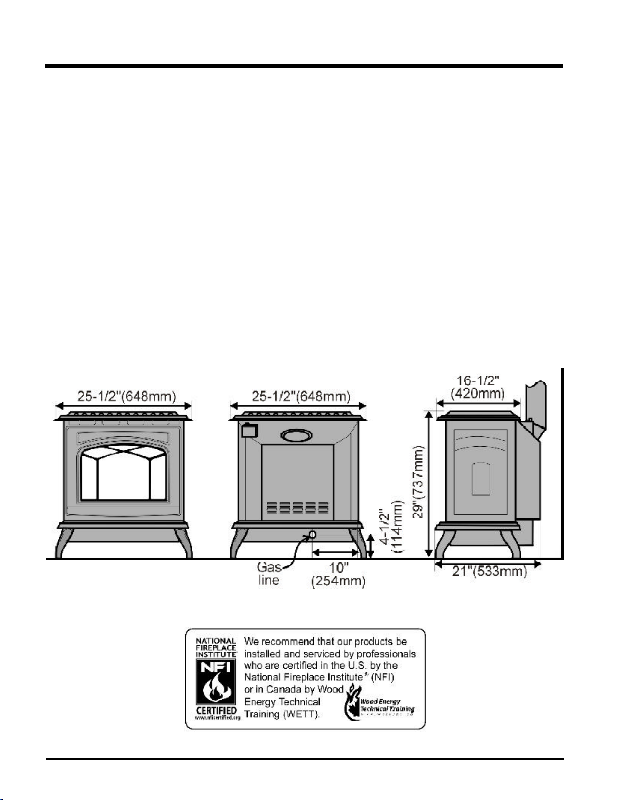
SPECIFICATIONS
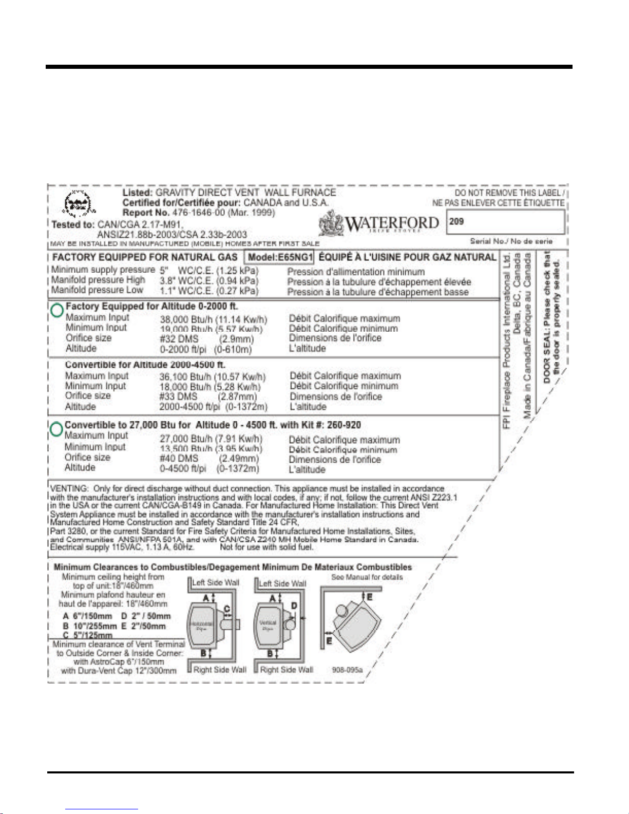
Fuels: E65-NG1 is approved for use with
natural gas.
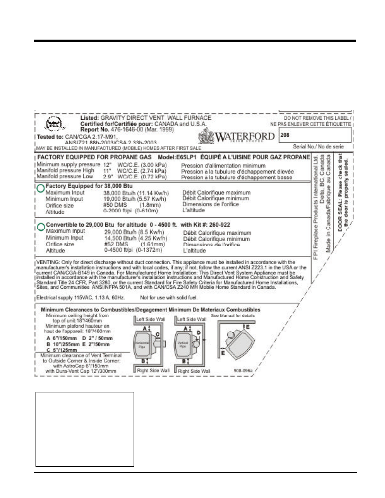
E65-LP1 is approved for use with
liquefiedpetroleumgases(propane).
Electrical: 120V A.C. system.
Circulation Fan: Variable speed, 125/75.
Log Sets: Ceramic fibre, 3 per set.
Vent System:Coaxial(6-5/8"outer/4"inner
liner) rigid flue and termination cap.
The efficiency rating of the appliance is a
product thermal efficiency rating determined
under continuous operating conditions and
was determined independent of any installed
system.
INFORMATION FOR
MOBILE/
MANUFACTURED
HOMES AFTER
FIRST SALE
This Waterford product has been tested and
listed by Warnock Hersey as a Direct Vent
RoomHeatertothefollowingstandards:CAN/
CGA 2.17-M91and ANSIZ21.88b-2003/CSA
2.33b-2003.
INSTALLATION
This Direct Vent System Appliance must be
installedinaccordancewiththemanufacturer's
installation instructions and the Manufactured
Home Construction and Safety Standard, Title
24 CFR, Part 3280, or thecurrent Standard of
Fire Safety Criteria for Manufactured Home
Installations, Sites, and Communities ANSI/
NFPA 501A, and with CAN/CSA Z240-MH Mo-
bile Home Standard in Canada.
Thisapplianceinstallationmustcomplywiththe
manufacturer's installation instructions and lo-
calcodes,ifany. Intheabsenceoflocalcodes
followthecurrentNationalFuelGasCode,ANSI
Z223.1andthecurrentNationalElectricalCode
ANSI/NFPA 70 in the U.S.A., and the current
CAN/CGA B149 Gas Installation Code and the
currentCanadian ElectricalCodeCSA C22.1in
Canada.
BEFORE YOU START
Safeinstallationandoperationofthisappliance
requires common sense, however, we are
required by the Canadian Safety Standards
andANSIStandardsto makeyouawareofthe
following:
1) Provide adequate clearances for servic-
ing, proper operation and around the air
openings into the combustion chamber.
2) The appliance must be installed on a flat,
solid,continuoussurface(e.g.wood,met-
al,concrete).Thismaybethefloor,oritcan
be raised up on a platform to enhance its
visual impact. The appliance may be in-
stalled on carpeting, tile, wood flooring or
other combustible material, because the
appliance's metal pedestal base extends
the full width and depth of the appliance.
The EMERALD Direct Vent Freestanding
GasStovecanbeinstalledinawidevariety
ofwaysandwillfitnearlyanyroomlayout.
It may be installed in a recessed position,
framed out into the room, or across a
corner.
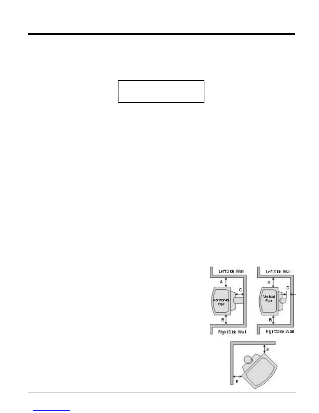
3) The EMERALD Direct Vent Freestanding
GasStove isapprovedfor alcoveinstalla-
tions, which meet the clearances listed on
page7. Thisunitisapprovedformanufac-
tured home installations, see page 8 and
THE CONTROL COMPARTMENT,
BURNERSANDCIRCULATINGAIR
PASSAGEWAYS OF THE APPLI-
ANCE BE KEPT CLEAN.
DUE TO HIGH TEMPERATURES,
THE APPLIANCE SHOULD BE LO-
CATED OUT OF TRAFFIC AND
AWAY FROM FURNITURE AND
DRAPERIES.
WARNING: FAILURE TO INSTALL
THIS APPLIANCE CORRECTLY
WILLVOIDYOURWARRANTYAND
MAY CAUSE A SERIOUS HOUSE
FIRE.
CHILDRENANDADULTSSHOULD
BE ALERTED TO THE HAZARDS
OF HIGH SURFACE TEMPERA-
TURES, ESPECIALLY THE FIRE-
PLACE GLASS, AND SHOULD
STAY AWAY TO AVOID BURNS
OR CLOTHING IGNITION.
YOUNG CHILDREN SHOULD BE
CAREFULLY SUPERVISEDWHEN
THEYAREINTHESAMEROOMAS
THE APPLIANCE.
CLOTHING OR OTHER FLAMMA-
BLE MATERIAL SHOULD NOT BE
PLACEDONORNEARTHEAPPLI-
ANCE.
This Waterford Mobile/Manufactured
Home Listed appliance comes factory
equipped with a means to secure the
unit.
This Waterford Mobile/Manufactured
Home listed appliance comes
equipped with a dedicated #8 ground
lug to which an 18 gauge copper wire
fromthesteelchassisgroundmustbe
attached.
Thisappliancemayonlybeinstalledin
an aftermarket permanently located,
manufactured (mobile) home, where
not prohibited by local codes.
This appliance is only use with the
type of gas indicated on the rating
plate. This appliance is not converti-
blefor usewith othergases,unlessa
certified kit is used.
INSTALLATION AND REPAIRS
SHOULD BE DONE BY A QUALI-
FIED SERVICE PERSON. THIS AP-
PLIANCESHOULDBEINSTALLED,
REPAIRED, INSPECTED BEFORE
USE AND AT LEAST ANNUALLY
BY A QUALIFIED SERVICE PER-
SON. MORE FREQUENT CLEAN-
ING MAY BE REQUIRED DUE TO
EXCESSIVE LINT FROM CARPET-
ING,ETC. ITISIMPERATIVETHAT