Waterford TARA T25 Direct Vent Freestanding Gas Stove 5
IMPORTANT:
SAVE THESE
INSTRUCTIONS
TheTARADirectVentFreestandingGasStove
must be installed in accordance with these
instructions.Carefully readall theinstructions
inthismanualfirst.Consultthebuildingauthor-
ityhavingjurisdictiontodeterminetheneedfor
a permit prior to starting the installation.
Note: Failure to follow the instructions
could cause a malfunction of the
heaterwhichcouldresultindeath,
seriousbodilyinjury,and/orprop-
erty damage. Failure to follow
these instructions may also void
your fire insurance and/or war-
ranty.
Note: These instructions take prece-
dence over Simpson Dura-Vent
instructions.
SPECIFICATIONS
Fuels: The TARA is factory equipped for
use with natural gas. A Propane
ConversionKit(#290-969)isavaila-
bletoconverttheTARAforusewith
liquefiedpetroleumgases(propane).
Electrical: 120V A.C. system.
Circulation Fan: Variable speed, 125/75
(Optional)
Log Sets: Ceramic fibre, 5 per set.
Vent System: Coaxial (6-5/8" outer / 4"
inner liner) rigid flue and
termination cap.
The efficiency rating of the appliance is a
product thermal efficiency rating determined
under continuous operating conditions and
was determined independent of any installed
system.
INFORMATION FOR
MOBILE/
MANUFACTURED
HOMES AFTER
FIRST SALE
This Waterford product has been tested and
listedbyWarnockHerseyasaDirectVentWall
Furnace to thefollowing standards: UL 307B-
1995,CAN/CGA-2.17-M91and ANSIZ21.88b-
2003/CSA 2.33b-2003.
INSTALLATION
This Direct Vent System Appliance must be
installed in accordance with the manufactur-
er's installation instructions and the Manufac-
turedHomeConstructionandSafetyStandard,
Title24CFR,Part3280,orthecurrentStandard
of Fire Safety Criteria for Manufactured Home
Installations,Sites,andCommunitiesANSI/NFPA
501A, and with CAN/CSA Z240-MH Mobile
Home Standard in Canada.
Thisapplianceinstallationmustcomplywiththe
manufacturer'sinstallationinstructionsandlocal
codes, if any. In the absence of local codes
follow the current National Fuel Gas Code,
ANSIZ223.1andthecurrentNationalElectrical
Code ANSI/NFPA 70 in the U.S.A., and the
current CAN/CGA B149 Gas Installation Code
and the current Canadian Electrical Code CSA
C22.1 in Canada.
INSTALLATION AND REPAIRS
SHOULDBEDONEBYAQUALIFIED
SERVICE PERSON. THIS APPLI-
ANCE SHOULD BE INSTALLED,
REPAIRED, INSPECTED BEFORE
USE AND AT LEAST ANNUALLY BY
A QUALIFIED SERVICE PERSON.
MORE FREQUENT CLEANING MAY
BE REQUIRED DUE TO EXCESSIVE
LINTFROMCARPETING,ETC. ITIS
IMPERATIVE THAT THE CONTROL
COMPARTMENT, BURNERS AND
CIRCULATINGAIRPASSAGEWAYS
BEFORE YOU START
Safeinstallationandoperationofthisappliance
requires common sense, however, we are
requiredbytheCanadianSafetyStandardsand
ANSI Standards to make you aware of the
following:
1) Provideadequateclearancesforservicing,
proper operation and around the air open-
ings into the combustion chamber.
2) The appliance must be installed on a flat,
solid,continuoussurface(e.g.wood,metal,
concrete).Thismaybethefloor,oritcanbe
raiseduponaplatformtoenhanceitsvisual
impact. The appliance may be installed on
carpeting, tile, wood flooring or other com-
bustible material. The TARA Direct Vent
Freestanding Gas Stove can be installed in
awidevarietyofwaysandwillfitnearlyany
roomlayout.Itmaybeinstalledinarecessed
position,framedoutintotheroom,oracross
a corner.
3) The TARA Direct Vent Freestanding Gas
Stove is approved for alcove installations,
whichmeettheclearanceslistedonpage6.
Thisunitisapprovedformanufacturedhome
installations, see page 6 and pages 9 to 17
for the required vent arrangements. If in-
stalled into a manufactured home the unit
must be bolted down to the floor.
4) Thisappliance isListedforbedroom instal-
lations when used with a Listed Millivolt
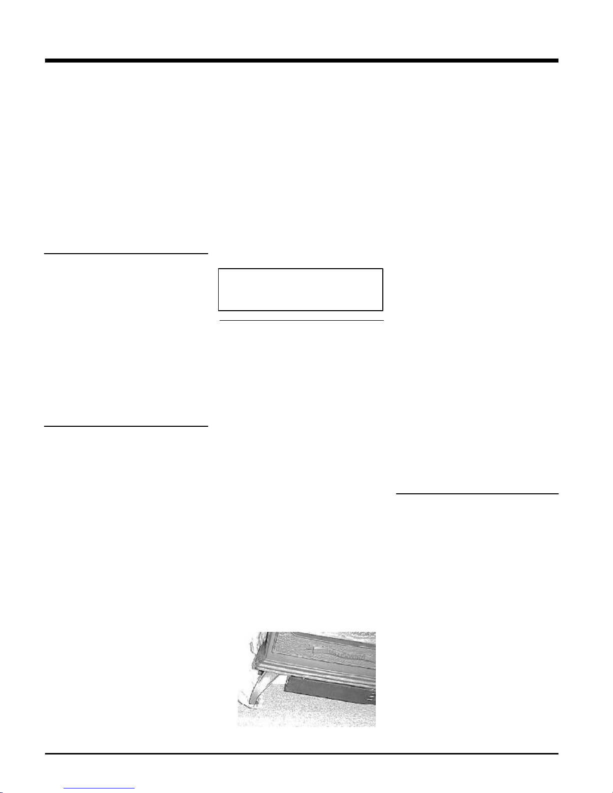
This Waterford Mobile/Manufactured
Home Listed appliance comes factory
equipped with a means to secure the
unit.
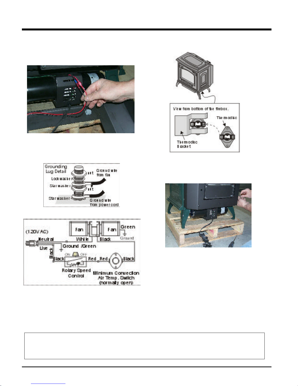
This Waterford Mobile/Manufactured
Homelistedappliancecomesequipped
withadedicated#8groundlugtowhich
an18gaugecopperwirefromthesteel
chassis ground must be attached.
This appliance may only be installed in
an aftermarket permanently located,
manufactured (mobile) home, where
not prohibited by local codes.
This appliance is only to be used with
the type of gas indicated on the rating
plate. This appliance is not convertible
forusewith other gases,unless acer-
tified kit is used.
OF THE APPLIANCE BE KEPT
CLEAN.
DUE TO HIGH TEMPERATURES,
THE APPLIANCE SHOULD BE LO-
CATED OUT OF TRAFFIC AND
AWAY FROM FURNITURE AND
DRAPERIES.
WARNING: FAILURE TO INSTALL
THIS APPLIANCE CORRECTLY
WILLVOIDYOURWARRANTYAND
MAY CAUSE A SERIOUS HOUSE
FIRE.
CHILDRENANDADULTSSHOULD
BE ALERTED TO THE HAZARDS
OF HIGH SURFACE TEMPERA-
TURES, ESPECIALLY THE FIRE-
PLACE GLASS, AND SHOULD
STAY AWAY TO AVOID BURNS
OR CLOTHING IGNITION.
YOUNG CHILDREN SHOULD BE
CAREFULLY SUPERVISEDWHEN
THEYAREINTHESAMEROOMAS
THE APPLIANCE.
CLOTHING OR OTHER FLAMMA-
BLE MATERIAL SHOULD NOT BE
PLACEDONORNEAR THEAPPLI-
ANCE.