Waterline FW60.2BL User manual

User Manual for your
FW60.2BL/SS 60 cm cooker hood
FW70.2BL/SS 70 cm cooker hood
FW90.3BL/SS 90 cm cooker hood
FW100.2BL/SS 100 cm cooker hood
NOTE: This User Instruction Manual contains important
information, including safety & installation points, which will
enable you to get the most out of your appliance. Please keep it
in a safe place so that it is easily available for future reference; for
you or any person not familiar with the operation of the appliance.
DD 30/10/09

3
Contents Page
Environmentalnote 4
IMPORTANT SAFETY INFORMATION 5 – 7
Specifications of your cooker hood 8 – 12
FW60.2BL/SS 8
FW70.2BL/SS 9
FW90.3BL/SS 10
FW100.2BL/SS 11
Optional extras (all models) 11 - 12
Using your cooker hood 12 - 13
Beforefirstuse 12
To use your cooker hood 12 - 13
Cleaning your cooker hood 13 - 14
The grease filters 14
Maintenance 14 - 17
Removing and cleaning the grease filters 14 - 15
Changingalightbulb 15-16
Fitting the carbon filters (ST1 carbon filters) 16 - 17
Installation 17 - 25
Electrical connection 17 - 18
Before beginning installation 18 - 19
Installing your cooker hood 19 - 21
Connecting to external ducting 22
Fitting the chimney 22 - 24
Completing the installation 25
Extraction mode or recirculation mode? 25
Troubleshooting 26 - 27
Contactdetails 29
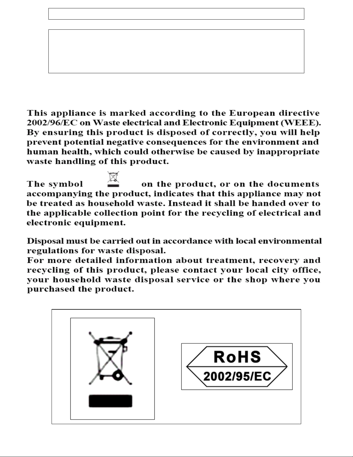
ENVIRONMENTAL NOTE
Note: Before discarding an old appliance, switch off and
disconnect it from the power supply. Cut off and render any
plug useless. Cut the cable off directly behind the appliance to
prevent misuse. This should be undertaken by a competent
person.
CONFORMITY TO W.E.E.E. DIRECTIVE
4
IMPORTANT SAFETY INFORMATION
Your safety is of the utmost importance to us. Please
make sure that you read this instruction booklet
before attempting to install or use the appliance. If
you are unsure of any of the information contained in
this booklet, please contact the Advice Line.
IMPORTANT: Any installation work must be
carried out by a qualified electrician or
competent person.
oThe hood must be installed in accordance with the installation
instructions and all measurements followed.
oIf the cooker hood is installed for use above a gas appliance then
the provision for ventilation must be in accordance with the Gas
Safety Codes of Practice BS.6172, BS.5440 & BS.6891 (Natural
Gas) and BS.5482 (LP Gas) 1994, the Gas Safety (Installation &
Use) Regulations, the Building Regulations issued by the
Department of the Environment, the Building Standards
(Scotland) (Consolidated) Regulations issued by the Scottish
Development Department.
oIt is dangerous to alter the specifications or to modify this
product. Do not tamper with it or attempt to modify the
appliance in any way.
oWhen installing the hood, ensure that the following
recommended distances are observed between the highest point
on the hob top (including the burners) and the bottom of the
cooker hood:
¾Electric cookers: 700 mm
¾Gas cookers: 700 mm
¾Coal/ oil cookers: 800 mm
IMPORTANT: DO NOT SET YOUR COOKER HOOD LESS
THAN 700mm ABOVE YOUR COOKER.
oWhen installed between adjoining wall cabinets, the cabinets
must not overhang the hob.
5
oThe edges of the cooker hood are sharp – be mindful of this as
you handle your appliance, especially during installation and
cleaning. DO NOT CLEAN IN BEHIND THE GREASE FILTERS!
oIf the room where the cooker hood is to be used contains a fuel
burning appliance such as a central heating boiler then its flue
must be of the sealed or balanced flue type.
oIf other types of flue or appliances are fitted, ensure that there is
an adequate supply of air in the room.
oWhen the hood is being used in its extractor function, ensure
that the ducting is fire retardant and that there are no bends
sharper than 90 degrees as this will reduce the efficiency of the
hood.
oEnsure the ducting for the extractor function has the same
diameter as the outlet hole all the way through.
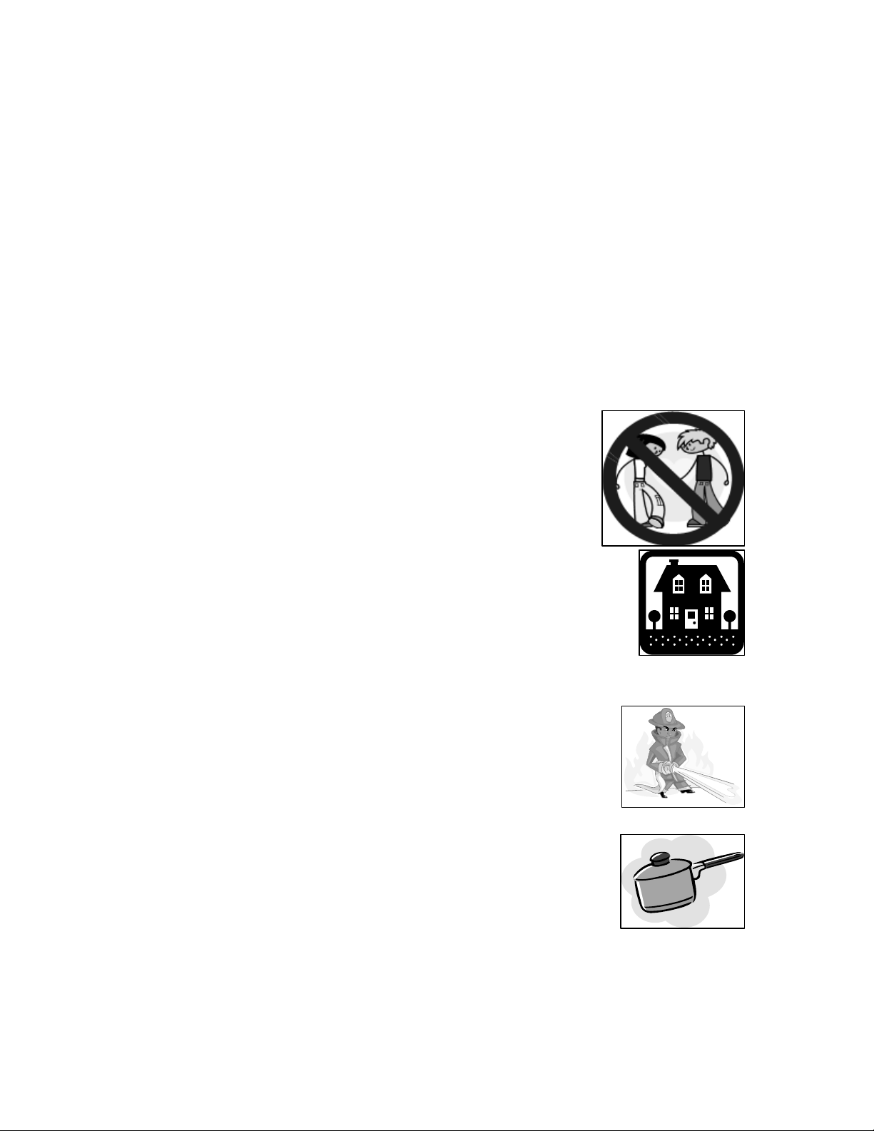
oKeep young children from using, playing with
or tampering with the cooker hood. Older
children and infirm persons should be
supervised if they are using the cooker hood.
oYour cooker hood is for domestic use only.
oPlease dispose of the packing material carefully – children are
especially vulnerable to it.
oDirty oil is an even greater fire risk.
oAlways put lids on pots and pans when cooking
on a gas cooker.
oThe manufacturer refuses to accept any responsibility for
damages arising to the hood or it catching on fire, from a failure
to observe the fire safety advice contained in this instruction
booklet.
6
This manual suits for next models
7
Table of contents
Popular Ventilation Hood manuals by other brands

Gorenje
Gorenje S3 IHGC963S4X manual

KOBE
KOBE ISX2136SQB-1 Installation instructions and operation manual

U.S. Products
U.S. Products ADVANTAGE-100H Information & operating instructions

Kuppersberg
Kuppersberg DUDL 4 LX Technical Passport

Framtid
Framtid HW280 manual

Thermador
Thermador HGEW 36 FS installation manual


