watt box WB-800I-FP User manual

1 2 3 Total
B1
B2
ACCESSORY OUTLET
(UNPROTECTED)
CURRENTVOLTAGE
POWER
WB-800I-FP
WB-800I-FP
WattBox® Rack Mountable Faceplate
Display | 220 - 240V
Quick Start Guide

2
Important Safety Instructions
Read and observe the following safety points at all times.
Notice
For indoor user only. Internal components are not sealed form the environment. The device can only be used in a fixed location
such as a telecommunication centre, or a dedicated computer room. When you install the device, ensure that the protective
earthing connection of the socket-outlet is verified by a skilled person. Suitable for installation in Information Technology Rooms
in accordance with Article 645 of the National Electrical Code and NFPA 75.
Only use brackets/attachments/accessories specified by the manufacturer.
Do not place the device in an unstable position where it might fail and cause injuries. This equipment is not suitable for use in
locations where children are likely to be present.
Do not cover this device with a cloth. Do not install it on a carpet or rug.

3
Key Features
• Connect up to three WB-800I series Power Distribution Units (PDUs) and two accessories (reserved for future use only).
• Two LED displays showing AC voltage and amperage of individual PDUs or the aggregate of all PDUs.
• Four USB ports that supply up to 1.5A each. Two on the front and two on the back.
• Three buttons for faceplate navigation and outlet control.
• Accessory outlet on the front panel (unprotected and non-controllable).
Package Contents
1 2 3 Total
B1
B2
ACCESSORYOUTLET
(UNPROTECTED)
CURRENTVOLTAGE
POWER
WB-800I-FP
Face plate
Pre-installed rack ears (2)
Rubber feet (4)
Removable, region-specific power cord
(in over-pack box, not PDU carton)
Install guide
IEC sleeve (1)

4
Rear Panel
1. Power Input – Input for 3-prong IEC power cord with detachable locking clip.
2. PDU Ports – Three green TIA-568B ports for connecting up to three 800I series PDUs to the 800I series faceplate.
3. Accessory Ports – Two gray TIA-568B ports. 3W maximum per port. Reserved for future use.
4. USB Ports – For powering USB devices. 1.5A maximum per port.
PDU Port Connections
This faceplate is OvrC enabled. To unlock the faceplate features in OvrC, you must
connect it to a compatible 800I series WattBox PDU on firmware version 2.3.0.0 or
newer.
Note: The WB-800ICH1U-IPVM-8 is not compatible.
TIA/EIA-568-B
TIA/EIA Standard 568-B (Gold Pins Facing Up)
Pin 1 - White/Orange
Pin 2 - Orange
Pin 3 - White/Green
Pin 4 - Blue
Pin 5 - White/Blue
Pin 6 - Green
Pin 7 - White/Brown
Pin 8 - Brown
1 2 3 4 5 6 7 8
1.5A 1.5A
USB POWERPDU
1 2 3
ACCESSORY
1 2
220 - 240 V~
50 / 60 Hz
10A
1 2 3 4

5
You can connect up to three 800I series PDUs to the faceplate. We recommend using TIA-568B pinout cables no longer than
4.5m / 15’.
Connect one end of the cable to the gray Accessory port of the PDU, and the other end of the cable to the faceplate’s green PDU port.
Pro Tip: Connect the faceplate to a PDU outlet that is turned on. Then, in OvrC, set that outlet’s Outlet Mode to Disabled.
Now, the faceplate will remain on when resetting all outlets of the connected 800I series WattBox.
Once the faceplate and 800I series WattBox PDU are connected, firmware updates are automatically pushed from the WattBox
connected to PDU port 1. During this update process the LEDs turn o and the faceplate is unresponsive. Allow five minutes for
the update to complete.
Warning: You must connect a PDU to PDU port 1 to keep the faceplate’s firmware up to date.
WB-800I-IPVM-6 PDU sold separately
50 / 60 Hz 10A
220~240V~
1.5A 1.5A
USB POWERPDU
1 2 3
ACCESSORY
1 2
220 - 240 V~
50 / 60 Hz
10A
WB-800I-FP

6
Front Panel
1. AC Power Button – Press and hold for three seconds to manually toggle the outlets on or o on all connected PDUs.
Outlets configured as Disabled or Reset Only are not aected on each connected PDU.
2. LED Indicators – See the status of the internet, safe voltage, surge protected, and whether the unit is properly Grounded.
See “LED Operation” on page 9.
3. Voltage Display – Displays the voltage (V) being supplied to the selected PDU from the wall outlet.
4. Output Current Display – Displays current draw in amps (A) for a single PDU or the total for all PDUs.
5. PDU Power Indicator – Has two states:
a. Blinking – The Current display shows the selected PDU’s current draw in amps (A).
b. Solid – The Current display shows the aggregate current draw of all connected PDUs.
6. Button 1 – Sequences through PDUs 1 through 3 and Total (left to right) displaying the current for the specified PDU. The
aggregate of all PDUs displays when Total is selected. This button is also used to reset individual PDUs. See “How to
Manually Reset Individual PDUs From the Faceplate” on page 7.
7. Button 2 – Sequences through Total and PDUs 3 through 1 (right to left) displaying the current for the specified PDU.
The aggregate of all PDUs displays when Total is selected. This button is also used to reset individual PDUs. See “How to
Manually Reset Individual PDUs From the Faceplate” on page 7.
8. USB Ports – For powering USB devices. 1.5A maximum per port.
9. Accessory Outlet (Unprotected and Non-Controllable) – Always-on, front-facing outlet for service use. A solid blue LED
indicates the outlet has power and is working.
1 2 3 Total
B1
B2
ACCESSORY OUTLET
(UNPROTECTED)
CURRENTVOLTAGE
POWER
WB-800I-FP
1 2 3 4 56 7 8 9

7
How to Manually Sequence Through Individual PDUs
• Tap B1 to sequence through PDUs 1-3 & Total (moving left to right).
• Tap B2 to sequence through Total and PDUs 3-1 (moving right to left).
As you sequence through the PDUs, the corresponding PDU LED flashes to indicate the selected PDU. The displays show the
corresponding voltage and current for the selected PDU.
Note: The LED flashes on the selected PDU for 5 minutes, during this time the display windows show the voltage and
current for the selected PDU. After 5 minutes, the faceplate returns to displaying the aggregate total of all the
connected PDUs.
How to Manually Reset Individual PDUs From the Faceplate
1. Tap B1 or B2 to sequence through the PDUs.
2. With the PDU number that needs to be reset flashing, press and hold B1 or B2 for 3 seconds. The Current display shows a
rotating 0as the outlet resets.
Note: Outlets configured as Disabled do not reset.

8
How to Manually Reset All Outlets From the Faceplate
Press and hold B1 and B2 at the same time for 3 seconds to reset all PDU outlets plugged into the faceplate. The Current display
shows a rotating 0as the PDU outlets reset.
Note: Outlets configured as Disabled do not reset.

9
LED Operation
Internet
Blue (Solid) All host pings are successful across all connected PDUs.
Blue (Slow Blink) Host ping partial fail across at least one of the connected PDUs.
Red (Solid) All host pings are failing on at least one of the connected PDUs.
Safe
Voltage
Blue (Solid) Enabled and safe on all connected PDUs.
Blue (Slow Blink) Enabled on all connected PDUs, but incoming AC Voltage is not safe on at least one of the
connected PDUs.
O Safe Voltage is disabled on at least one of the connected PDUs.
Surge
Protected
Blue (Solid) All connected PDUs are protected.
Blue (Slow Blink) At least one of the connected PDUs is unprotected.
O All connected PDUs are unprotected.
Grounded
Blue (Solid) All connected PDUs are grounded.
Blue (Slow Blink) At least one of the connected PDUs is not grounded.
O All connected PDUs are not grounded.
10
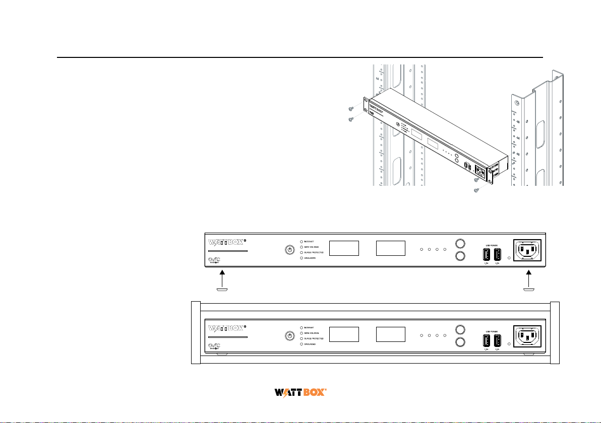
Mounting Options
The WB-800I-FP can be rack-mounted or placed in a cabinet.
Rack Mounting
Install the WattBox faceplate into the rack using the pre-in-
stalled rack ears and four 10-32 rack screws for AV racks, or
12-24 rack screws for IT racks (rack screws not included).
Cabinet Placement
Remove the pre-installed
rack ears, if desired, and
attach the supplied feet to
the bottom of the WattBox
faceplate for cabinet
placement.
1 2 3 Total
B1
B2
ACCESSORY OUTLET
(UNPROTECTED)
CURRENTVOLTAGE
POWER
WB-800I-FP
1 2 3 Total
B1
B2
ACCESSORY OUTLET
(UNPROTECTED)
CURRENTVOLTAGE
POWER
WB-800I-FP
1 2 3 Total
B1
B2
ACCESSORY OUTLET
(UNPROTECTED)
CURRENTVOLTAGE
POWER
WB-800I-FP
1 2 3 Total
B1
B2
ACCESSORYOUTLET
(UNPROTECTED)
CURRENTVOLTAGE
POWER
WB-800I-FP
1 2 3 Total
B1
B2
ACCESSORY OUTLET
(UNPROTECTED)
CURRENTVOLTAGE
POWER
WB-800I-FP
1 2 3 Total
B1
B2
ACCESSORY OUTLET
(UNPROTECTED)
CURRENTVOLTAGE
POWER
WB-800I-FP

11
Mounting Options
The WB-800I-FP can be rack-mounted or placed in a cabinet.
Rack Mounting
Install the WattBox faceplate into the rack using the pre-in-
stalled rack ears and four 10-32 rack screws for AV racks, or
12-24 rack screws for IT racks (rack screws not included).
Cabinet Placement
Remove the pre-installed
rack ears, if desired, and
attach the supplied feet to
the bottom of the WattBox
faceplate for cabinet
placement.
1 2 3 Total
B1
B2
ACCESSORY OUTLET
(UNPROTECTED)
CURRENTVOLTAGE
POWER
WB-800I-FP
1 2 3 Total
B1
B2
ACCESSORY OUTLET
(UNPROTECTED)
CURRENTVOLTAGE
POWER
WB-800I-FP
1 2 3 Total
B1
B2
ACCESSORY OUTLET
(UNPROTECTED)
CURRENTVOLTAGE
POWER
WB-800I-FP

12
Technical Support
For chat and telephone, visit snp1.co/techsupport • Email: T[email protected]. Visit snp1.co/tc for discussions, instructional videos,
news, and more.
Warranty and Legal Notices
Find details of the product’s Limited Warranty at snapone.com/legal/ or request a paper copy from Customer Service at 866.424.4489.
Find other legal resources, such as regulatory notices and patent and safety information, at snapone.com/legal/ .
Copyright ©2022, Snap One, LLC. All rights reserved. Snap One its respective logos are registered trademarks or trademarks of Snap
One, LLC (formerly known as Wirepath Home Systems, LLC), in the United States and/or other countries. 4Store, 4Sight, Control4,
Control4 My Home, SnapAV, and WattBox are also registered trademarks or trademarks of Snap One, LLC. Other names and brands
may be claimed as the property of their respective owners. Snap One makes no claim that the information contained herein covers all
installation scenarios and contingencies, or product use risks. Information within this specification subject to change without notice. All
specifications subject to change without notice.
Version 221128
200-00732-C WB-800I-FP
This manual suits for next models
1
Table of contents
Other watt box Monitor manuals


