watt box WB-800-FP User manual

WB-800-FP
WattBox® Rack Mountable Faceplate Display
Quick Start Guide

2
Key Features
• Connect up to three WB-800 series Power Distribution Units (PDUs) and two accessories (for future use only).
• Two LED displays showing AC voltage and amperage of individual PDUs or the aggregate of all PDUs.
• Four USB ports that supply up to 1.5A each. Two on the front and two on the back.
• Three buttons for faceplate navigation and outlet control.
• Accessory outlet on the front panel (unprotected and non-controllable).
Package Contents
• 1x WB-800-FP
• 2x Rack ears with included chassis screws (already installed)
• 1x 6ft power cord
• 1x Locking clip to secure IEC power cord
• 4x Rubber feet
• 1x Install Guide
3
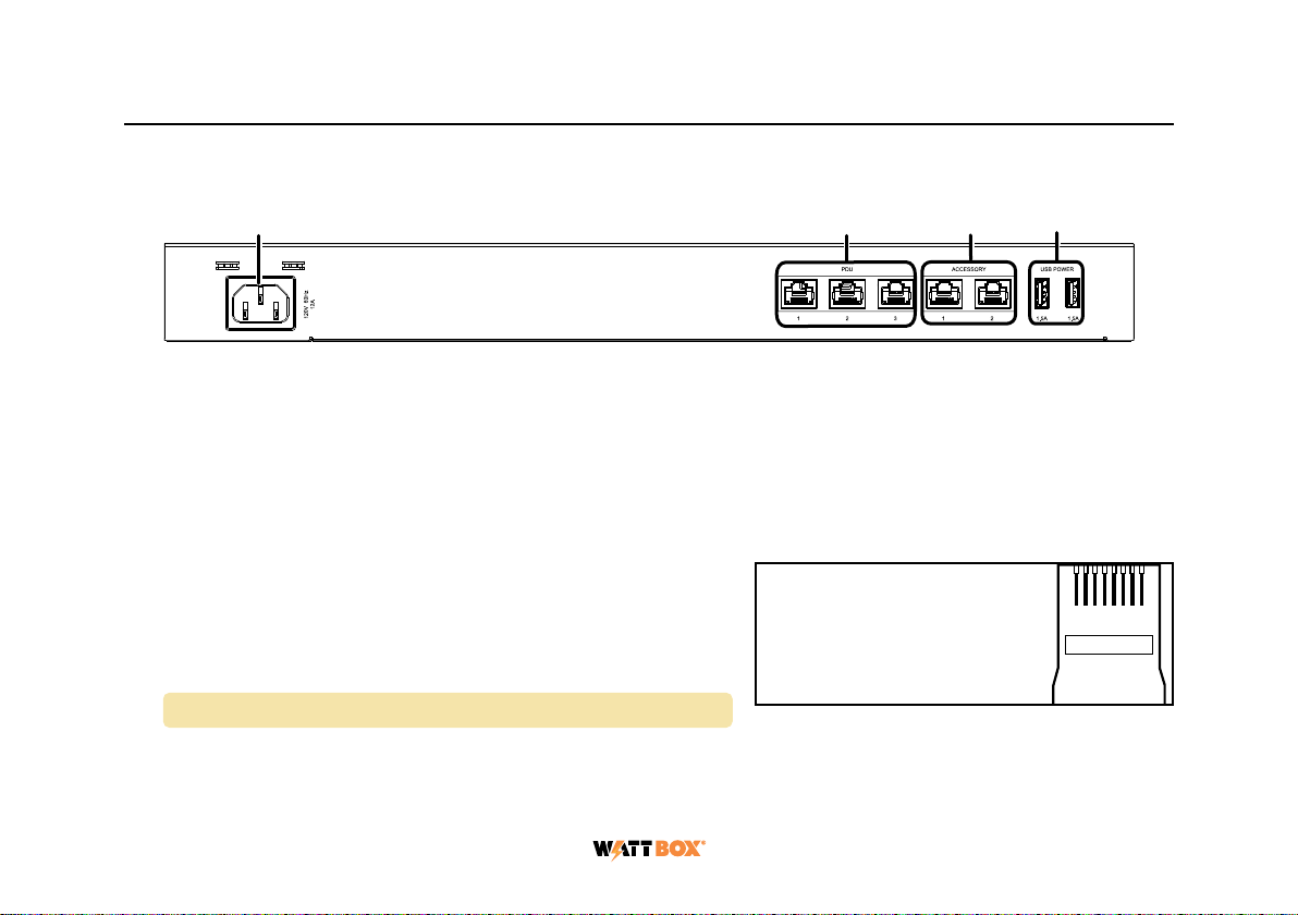
Rear Panel
1. Power Input – Input for 3-prong IEC power cord, with detachable locking clip.
2. PDU Ports – Three green, TIA-568B ports for connecting up to three 800 series PDUs to the 800 series
faceplate.
3. Accessory Ports – Two gray, TIA-568B ports. 3W maximum per port. Reserved for future use.
4. USB Ports – For powering USB devices. 1.5A maximum per port.
PDU Port Connections
This faceplate is OvrC enabled. To unlock the faceplate features
in OvrC, you must connect it to a compatible 800 series WattBox
PDU on firmware version 2.2.0.8 or newer.
Note: The WB-800CH1U-IPVM-8 is not compatible.
You can connect up to three 800 series PDUs to the faceplate. We recommend using TIA-568B pinout cables no
longer than 15’.
TIA/EIA-568-B
TIA/EIA Standard 568-B (Gold Pins Facing Up)
Pin 1 - White/Orange
Pin 2 - Orange
Pin 3 - White/Green
Pin 4 - Blue
Pin 5 - White/Blue
Pin 6 - Green
Pin 7 - White/Brown
Pin 8 - Brown
1 2 3 4 5 6 7 8
1 2 3 4

4
Connect one end of the cable to the gray Accessory port of the PDU, and the other end of the cable to the
faceplate’s green PDU port.
Pro Tip: Set the Outlet Mode to Disabled for the outlet the faceplate is connected to, in OvrC. This ensures
the faceplate does not lose power when resetting all outlets of the connected 800 series WattBox.
If you’re connecting the faceplate to a WB-800-IPVM-12, use the dedicated Accessory outlet on the
back of the PDU.
Once the faceplate and 800 series WattBox PDU are connected, firmware updates are automatically pushed
from the WattBox connected to PDU port 1. During this update process the LEDs turn o and the faceplate is
unresponsive. Allow five minutes for the update to complete.
Warning: You must connect a PDU to PDU port 1 to keep the faceplate’s firmware up-to-date.
WB-800-FP
800 series PDU sold separately
CONT ROLL ED 1 CONT ROLLED 2 CONT ROLL ED 3 CONT ROLL ED 4 CO NTRO LLED 5 CONTR OLLE D 6
NETWOR K
RESET
120VA C 60Hz
POWER
SAFE
VOLTAGE
ACCUPS L IN K
OFF
ON
WB-800-IPVM-12
CONT ROLL ED 7
FILTERED
CONT ROLL ED 8 CONT ROLL ED 9 CONT ROLL ED 10 CONT ROLL ED 11 CONT ROLL ED 12
5
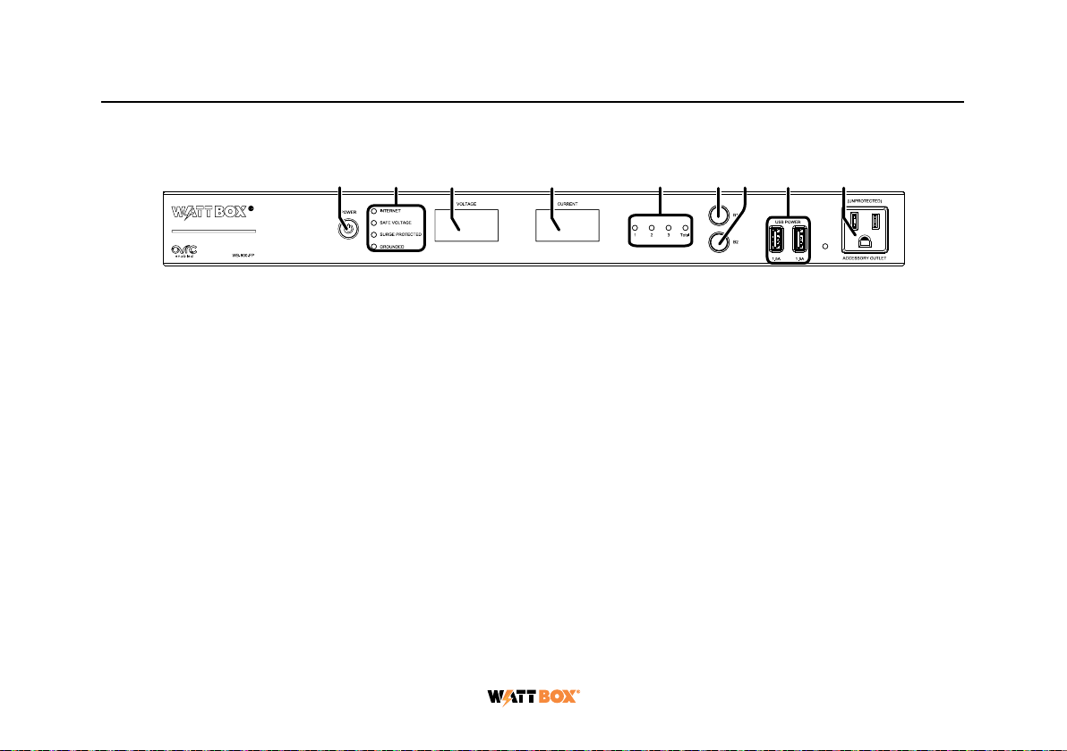
Front Panel
1. AC Power Button – Press and hold to manually toggle the outlets on or o on all connected PDUs. Outlets
configured as Disabled or Reset Only are not aected on each connected PDU.
2. LED Indicators – See the status of the internet, safe voltage, surge protected, and whether the unit is
properly Grounded. See “LED Operation” on page 8.
3. Voltage Display – Displays the voltage (V) being supplied from the outlet.
4. Output Current Display – Displays current draw in amps (A). This figure can be an aggregate of the
combined PDUs or a single PDU.
5. PDU Power Indicator – Has two states:
a. Blinks – The Current display is showing the selected PDU’s current draw in amps (A).
b. Solid – The Current display shows the aggregate of all connected PDUs.
6. Button 1 – Sequences through PDUs 1 through 3 and Total (left to right) displaying the Current for the
specified PDU. Aggregate of all PDUs display when landing on Total. This button is also used to reset
individual PDUs. See “How to Manually Reset Individual PDUs From the Faceplate” on page 7.
7. Button 2 – Sequences through Total and PDUs 3 through 1 (right to left) displaying the Current for the
1 2 3 4 5 6 7 8 9

6
specified PDU. Aggregate of all PDUs display when landing on Total. This button is also used to reset
individual PDUs. See “How to Manually Reset Individual PDUs From the Faceplate” on page 7.
8. USB Ports – For powering USB devices. 1.5A maximum per port.
9. Accessory Outlet (Unprotected and Non-Controllable) – Always-on, front-facing outlet for service use. A
solid blue LED indicates the outlet has power and is working.
How to Manually Sequence Through Individual PDUs
• Tap B1 to sequence through PDUs 1-3 & Total (moving left to right).
• Tap B2 to sequence through Total and PDUs 3-1 (moving right to left).
As you sequence through the PDUs, the corresponding PDU LED flashes to indicate which PDU number you are on.
The displays show the corresponding Current for the PDU specified.
Note: The LED light flashes on the specified PDU for 5 minutes, during this time the display windows show
the Current for the selected PDU. Once the 5 minutes has expired, the faceplate defaults back to
displaying the aggregate Total of all the connected PDUs.

7
How to Manually Reset Individual PDUs From the
Faceplate
1. Tap B1 or B2 to sequence through the PDUs.
2. With the PDU number that needs to be reset flashing, press and hold B1 OR B2 for 3 seconds. The Current
display shows a rotating 0as the outlet resets.
Note: Outlets configured as Disabled do not reset.
How to Manually Reset All Outlets From the Faceplate
Press and hold B1 and B2 at the same time for 3 seconds to reset all PDU outlets plugged into the faceplate. The
Current display shows a rotating 0as the PDU outlets reset.
Note: Outlets configured as Disabled do not reset.

8
LED Operation
Internet
Blue (Solid) All host pings are successful across all connected PDUs.
Blue (Slow Blink) Host ping partial fail across at least one of the connected PDUs.
Red (Solid) All host pings are failing on at least one of the connected PDUs.
Safe
Voltage
Blue (Solid) Enabled and safe on all connected PDUs.
Blue (Slow Blink) Enabled on all connected PDUs, but incoming AC Voltage is not safe on at
least one of the connected PDUs.
O Safe Voltage is disabled on at least one of the connected PDUs.
Surge
Protected
Blue (Solid) All connected PDUs are protected.
Blue (Slow Blink) At least one of the connected PDUs is unprotected.
O All connected PDUs are unprotected.
Grounded
Blue (Solid) All connected PDUs are grounded.
Blue (Slow Blink) At least one of the connected PDUs is not grounded.
O All connected PDUs are not grounded.
9
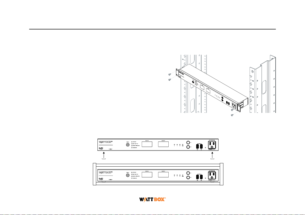
Mounting Options
The WB-800-FP can be rack-mounted or placed in a cabinet.
Rack Mounting
Install the WattBox faceplate into the rack using the
pre-installed rack ears and four 10-32 rack screws for AV
racks, or 12-24 rack screws for IT racks (rack screws not
included).
Cabinet Placement
Remove the pre-installed rack ears, if desired, and attach the supplied feet to the bottom of the WattBox faceplate
for cabinet placement.

10
Technical Support
For chat and telephone, visit tech.control4.com/s/contactsupport • Email: T[email protected]. Visit tech.
control4.com for discussions, instructional videos, news, and more.
Warranty and Legal Notices
Find details of the product’s Limited Warranty at snapone.com/legal/ or request a paper copy from Customer Service at
866.424.4489. Find other legal resources, such as regulatory notices and patent and safety information, at snapone.com/
legal/ .
Copyright ©2022, Snap One, LLC. All rights reserved. Snap One its respective logos are registered trademarks or
trademarks of Snap One, LLC (formerly known as Wirepath Home Systems, LLC), in the United States and/or other
countries. 4Store, 4Sight, Control4, Control4 My Home, SnapAV, and WattBox are also registered trademarks or
trademarks of Snap One, LLC. Other names and brands may be claimed as the property of their respective owners. Snap
One makes no claim that the information contained herein covers all installation scenarios and contingencies, or product
use risks. Information within this specification subject to change without notice. All specifications subject to change
without notice.
220118
200-00731-A_WB-800-FP
Table of contents
Other watt box Monitor manuals

Popular Monitor manuals by other brands


ViewSonic
ViewSonic VE710b-1 Service manual

Tanita
Tanita InnerScan BC-543 instruction manual

Defender Security
Defender Security DFR-MN-215HD quick start guide

Samsung
Samsung 400FP-2 - SyncMaster - 40" LCD Flat Panel... user manual

Geemarc
Geemarc ClearSound AMPLICALL 30 user guide

LG
LG MU-50PM10 Service manual