WattMaster CommLink IV User manual
CommLink IV
Setup Guide
www.wattmaster.com
STATUS
www.wattmaster.com
RX-USB
TX-USB
COMM
TX-CPU
RX-CPU
ACT-LAN
LNK-LAN
CONTROLS
CommLink IV

Table of Contents
WattMaster Controls, Inc.
8500 NW River Park Drive · Parkville, MO 64152
Toll Free Phone: 866-918-1100
PH: (816) 505-1100 · FAX: (816) 505-1101 · E-mail: mail@wattmaster.com
Visit our web site at www.wattmaster.com
Form: WM-CMLKIV-INST-01A Copyright 2008 WattMaster Controls, Inc.
WattMaster Controls, Inc. assumes no responsibility for errors or omissions.
This document is subject to change without notice.
General Information......................................................................................................................................... 3
CommLink IV Overview................................................................................................................................................................3
Optional IP Module Kit..................................................................................................................................................................3
Optional Remote Link...................................................................................................................................................................3
Installing CommLink IV ONLY ......................................................................................................................................................3
System Requirements..................................................................................................................................................................3
Connection and Wiring .................................................................................................................................... 4
Communication Settings ................................................................................................................................. 5
CommLink IV USB Driver Installation Instructions ........................................................................................ 6
USB Serial Converter Software Installation..................................................................................................................................6
USB Serial Port Software Installation...........................................................................................................................................7
Finding what COM Port # the CommLink IV is Using...................................................................................................................8
Changing the USB Serial COM Port Number...............................................................................................................................9
Prism USB Driver Installation Instructions ................................................................................................... 10
CommLink IV LED Descriptions .................................................................................................................... 12
Connecting the Network ............................................................................................................................... 13
Proxy and Firewall Compatibility ................................................................................................................................................13
Troubleshooting ............................................................................................................................................. 14
Troubleshooting Procedures ......................................................................................................................................................14

CommLink IV Setup Guide
3
Operator Interface
CommLink IV Overview
The CommLink IV is used to transfer communications between
controllers on your control system loops. It can also be used as
an interface for connection of a computer to your system.
The CommLink IV provides communication with the control
system through any computer that is running Prism software.
For remote communications, an IP Module Kit can be installed
for LAN and Internet connections or a Remote Link can be con-
nected for dial-up connections.
Optional IP Module Kit
The OE415-02 IP Module Kit, when installed and congured in
the CommLink IV communication interface, provides TCP/IP
Internet and/or intranet connection for Ethernet networked com-
puter systems allowing them to communicate with your control
system. The OE415-02 IP Module Kit consists of the IP Module
and a 10 ft. long CAT5 Ethernet crossover cable.
Using standard TCP/IP Protocol, with WattMaster’s Prism soft-
ware, you are able to monitor and congure your controllers
without a modem or a direct connection from a PC. Utilizing
existing routers, proxies, or rewalls allows a PC running Prism
to connect to a controller in a remote accessible location or build-
ing. Several IP connection proles can be created to facilitate
monitoring several CommLink IVs with IP Module Kits installed
on individual sites.
Optional Remote Link
The OE-419-06 Remote Link is a 14,400 baud modem that can
be used with a CommLink IV or a computer. It is used to provide
remote dial-up communications with the CommLink IV. When it
is used as a computer modem (at the remote computer location),
it connects to the remote computer.
NOTE: WattMaster will not support any other internal or
external modems by other manufacturers.
The Remote Link connects to the CommLink IV communications
interface at the control system location via a DB9 serial cable.
A telephone line connects the Remote Link to the local phone
service. Connection is made by dialing the telephone number
of the job site where the Remote Link is located. Using another
Remote Link modem connected to a computer at a remote loca-
tion, the control system can be monitored and controlled using
the Prism computer front end software package.
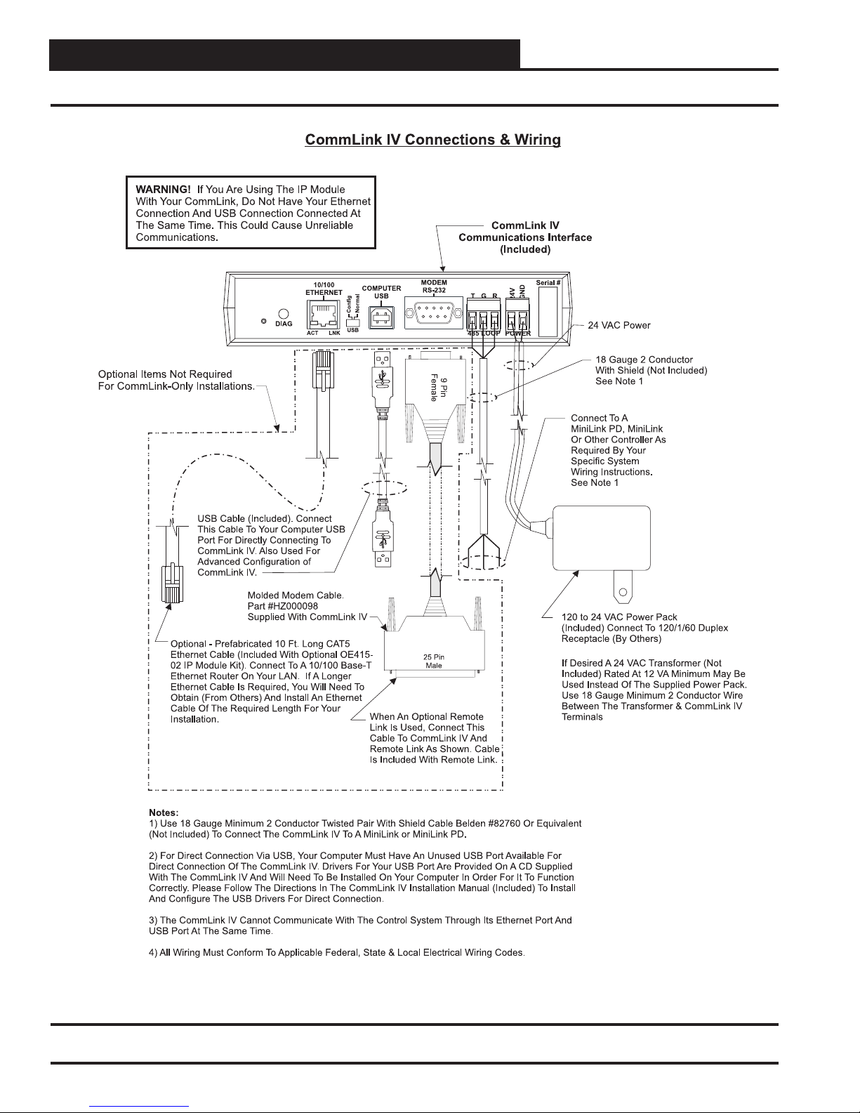
Installing CommLink IV ONLY
When you are using the CommLink IV in an application without
a computer, Remote Link, or IP Link Module, wire the RS-485
loop terminal to a MiniLink, MiniLink PD, or other controller on
your controls loop as required by your specic system.
Connect the power pack to a 110 volt wall outlet and connect
its wires to the power terminal block on the CommLink IV. If
desired, a 24 vac transformer rated at 12 VA minimum may be
used instead of the supplied power pack. Use 18 gauge minimum
2 conductor wire between the transformer and CommLink IV
terminals. Set the dip switch on the CommLink IV as shown in
Figure 2.
System Requirements
To program the CommLink IV to work with Prism, you will
need:
Standard Items (Required)
• CommLink IV with power adapter
• A PC with an Ethernet communications port or USB
port (supplied by others)
• Microsoft Windows 98, NT, 2000, XP, or Vista
(must be installed on the PC you are going to use)
• Prism software CD (ordered separately from
WattMaster)
Optional Items
• CommLink IP Module that comes with
Ethernet RJ-45 Crossover CAT 5, 10 ft. long cable for
LAN, and Internet remote communications
• Remote Link that comes with connection
cables for dial up remote communications
General Information
CommLink IV Setup Guide
4Operator Interface
Connection and Wiring
Figure 1: CommLink IV Connection & Wiring

CommLink IV Setup Guide
5
Operator Interface
Communication Settings
Figure 2: CommLink IV Communication Settings

CommLink IV Setup Guide
6Operator Interface
CommLink IV USB Driver Installation Instructions
You must follow the included CommLink IV Communications
Interface connection and wiring instructions sheet to connect and
congure the CommLink IV before beginning the USB driver
installation procedure.
USB Serial Converter
Software Installation
CAUTION: You must use the drivers on the CD-ROM
supplied with the CommLink IV. DO NOT
download drivers from the FTDI website,
because these will not work for the
CommLink IV Communication Interface!
1. Insert the CommLink IV CD-ROM into your CD-
ROM drive.
2. Apply power to the CommLink IV if it is not powered
up already.
3. A message should pop up from the Tool bar that
reads, “Found New Hardware.” Click on the Found
New Hardware Wizard application from the Tool
Bar.
4. The window that appears will ask the question, “Can
Windows connect to Windows Update to search for
software?” as shown below. Select “No, not this time”
and click <Next>.
5. The next window that appears asks, “What do you
want the wizard to do?” Select “Install from a list or
specic location (Advanced)” as shown below and
click <Next>.
6. On the next window as shown below make sure
that “Search for the best driver in these locations” is
selected. Uncheck the box that reads, “Search remov-
able media” and instead check the box “Include this
location in the search:”
7. Click <Browse> and locate the drive that your CD-
ROM is located on. Click <Next>.
CommLink IV Setup Guide
7
Operator Interface
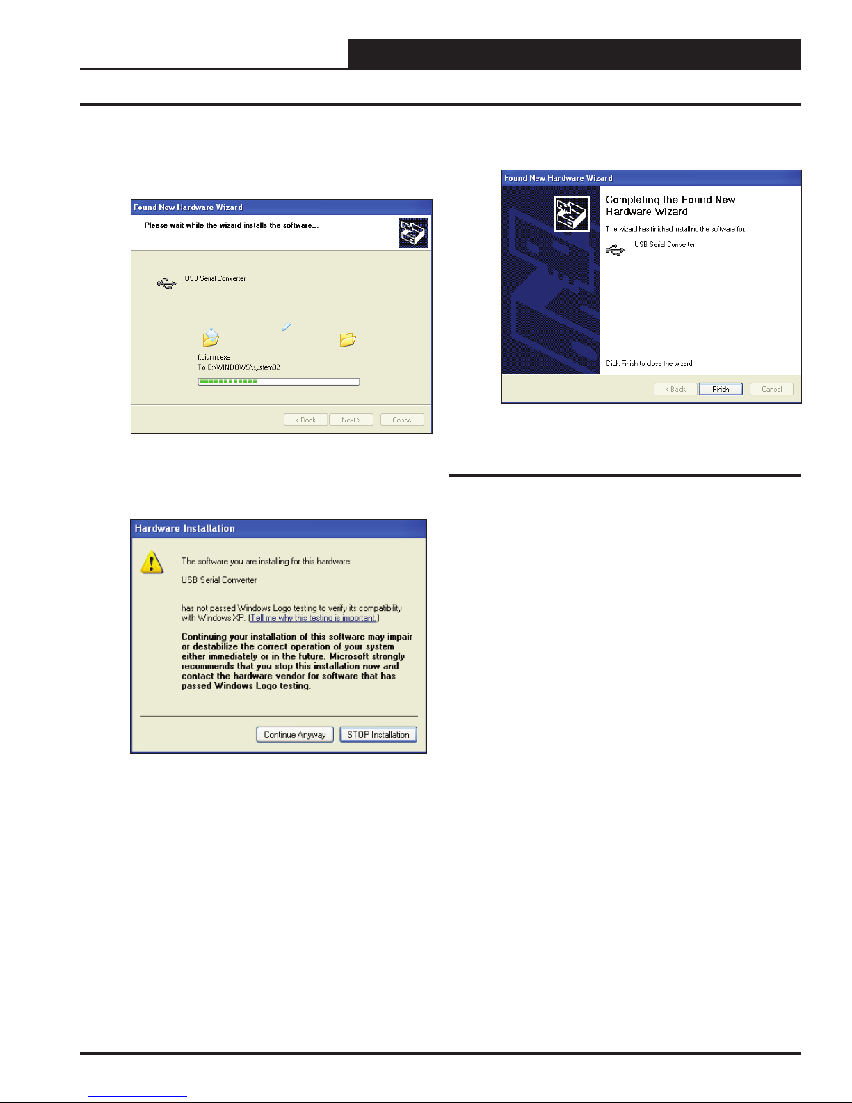
8. The next window will search and nd the les it
needs to download and will start downloading them
as shown below.
9. While the les are downloading, a Hardware Instal-
lation window might pop up as shown below. Click
<Continue Anyway>.
10. The wizard will then nish installing the software.
11. Once the wizard is done, click <Finish>.
USB Serial Port Software Installation
1. Once the Serial Converter software is installed, the
Found New Hardware Wizard will appear again to
download the USB Serial Port software.
2. Follow steps 1 though 7 of the previously described
USB Serial Converter Installation instructions.
3. Click <Finish> when the wizard is done download-
ing the software.
4. WinXP requires you to restart your computer before
new settings will take effect.
CommLink IV USB Driver Installation Instructions

CommLink IV Setup Guide
8Operator Interface
Finding What COM Port # the
CommLink IV is Using
1. Left-click on <Start>, located on the bottom left of
the Windows Tool Bar.
2. Select <Control Panel>.
3. Double-click the System Icon.
4. Click the <Hardware> tab.
5. Click the <Device Manager> button.
6. Click on the plus sign next to Ports to see all of the
common ports.
7. Locate the USB Serial Port (COM#). The COM# in
parentheses is the port it is located on. Write this com
port number down. You will need to know this when
setting up the Prism software.
CommLink IV USB Driver Installation Instructions

CommLink IV Setup Guide
9
Operator Interface
CommLink IV USB Driver Installation Instructions
Changing the USB Serial COM Port
Number
When the CommLink IV is rst plugged in, it will be assigned
a COM Port Number to be used for communicating with the
Prism software. If the port number is higher than 9, it needs to be
changed to a value less than 9 to be recognized by Prism. Follow
the steps below to do this.
1. Click <Start>, click <Control Panel>, click
<System>, and then click the <Hardware> tab
and then click <Device Manager> to get to the
Device Manager Window.
2. Click on the plus sign next to Ports to see all of the
common ports.
3. Right-click on “USB Serial Port (COM#)” and select
<Properties>. In the Properties Window, select the
<Port Settings> tab.
4. Change the Bits per Second (Baud Rate) to 19200.
Then click on <Advanced>.
5. In the COM Port Number drop box, select which
COMM Port you wish to use. Be sure you do not
select a COM number that is already in use. Select a
port that is less than 10.
6. Once you select the correct COM Port Number, click
<OK> and close any windows opened in the process
of changing the port number.

CommLink IV Setup Guide
10 Operator Interface
Prism USB Driver Installation Instructions
Setting Up Prism
1. Open your Prism software.
2. Click on the Key button and type in the
password “sm”.
3. Click <Done>.
4. If Prism is online, click <Communications> and
then click <Go Ofine>.
5. Click on the Edit Jobsite button to enter
jobsite information.
6. Click on an empty location. Type in a job name and
press <Enter>.
7. Double-click in the Port location on the same line as
the job name. The PortCtl Class Properties Window
will pop up.
8. Click on the down arrow on the Port pull down box
and select the Comm. Port # that the CommLink IV
is using. This port number is the one you should have
found in the Device Manager previously. Click
<Apply> and then click <OK>.
9. If you are using a Single Version CommLink, type a
“1” in the CommLink eld in the Job Site Window
and press <Enter>. For all other congurations,
leave “0” in the eld.
10. Click <Done>.
11. Click <Communications> again and select <Go
OnLine>.
12. Click <Communications> again and select
<Search for Units>.

CommLink IV Setup Guide
11
Operator Interface
13. The Search for Installed Units Window will pop up.
Click <Start> to start the search.
14. If everything is working correctly, Units Found on
this Loop should increment.
15. If Units Found on this Loop stays at zero, check the
wiring to the CommLink IV and/or read through these
directions again to make sure all steps were followed.
Prism USB Driver Installation Instructions
CommLink IV Setup Guide
12 Operator Interface
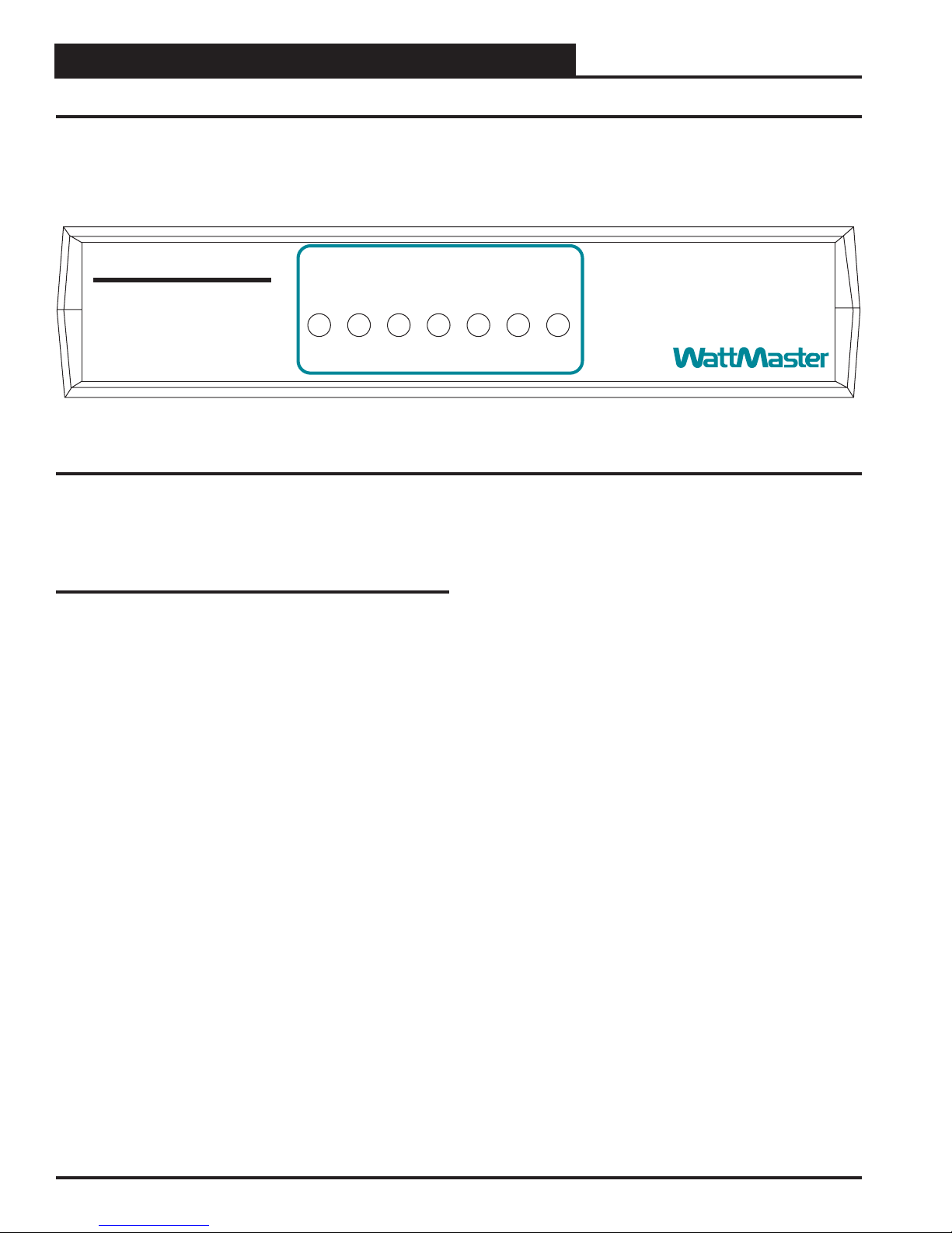
CommLink IV LED Descriptions
Figure 3: CommLink IV LED Display
STATUS
RX-USB
TX-USB
LOOP
TX-CPU
RX-CPU
ACT-LAN
LNK-LAN
CONTROLS
CommLink IV
www.wattmaster.com
CommLink IV LED Descriptions
LOOP - Indicates communication activity on local controller
network. This LED ickers off when data is exchanged with
the controller network.
TX-USB - Indicates transmitted data status of USB connec-
tion. This LED only ashes when your CommLink is
connected to a computer and data is sent to Prism from the
CommLink via USB.
RX-USB - Indicates received data status of USB connection.
This LED only ashes when your CommLink is connected
to a computer and data is sent from Prism to the CommLink
via USB.
TX-CPU - Indicates transmitted data status. This LED only
ashes when your CommLink is connected to a computer
and data is sent to Prism from the CommLink using USB or
Ethernet.
RX-CPU - Indicates received data status. This LED only
ashes when your CommLink is connected to a computer
and data is sent from Prism to the CommLink using USB or
Ethernet.
ACT-LAN - Indicates activity on the local area network. This
LED ashes on when LAN is transmitting and receiving
data and is only operational when the IP Module Kit is
installed.
LNK-LAN - Indicates local area network is connected. This
LED is on when connected to LAN and is only operational
when the IP Module Kit is installed.
CommLink IV Setup Guide
13
Operator Interface
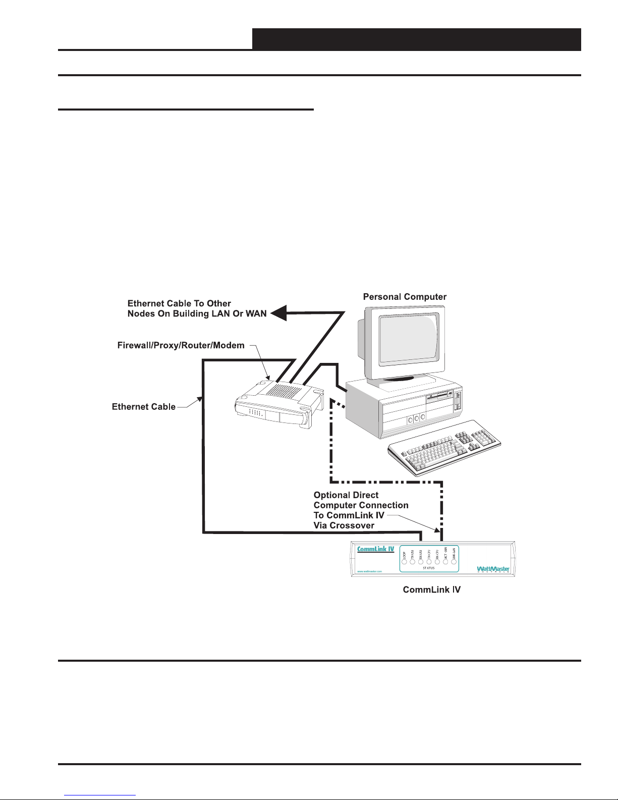
Connecting the Network
Figure 4: Example Network Diagram of a Firewall or Proxy Conguration
Proxy and Firewall Compatibility
Proxy and Firewall congurations may become necessary
when the CommLink IV is connected to a LAN/WAN that is
protected by a commercially available Firewall, Proxy, or NAT
enabled router. Examples of these would include Cisco, NetGear,
LinkSys, or WatchGuard Technologies. Also, some ISPs provide
IP Address ranges that are already re-walled at the NOC or ISP
Head-End. Make sure that your IT Department or ISP can create
a mapped TCP port 39288 on your rewall/proxy to TCP port
39288 on the assigned IP Address of the CommLink IV.
Only with proper conguration of the Firewall/Proxy are connec-
tions to the CommLink IV from outside of the local area network
going to be possible. Check that the Firewall/Proxy port is not
set to time out or reset after a specied amount of time passes
unless there is no trafc from the remote PC.

CommLink IV Setup Guide
14 Operator Interface
Troubleshooting
Troubleshooting Procedures
Prism Software Verify that the correct Comm Port, created
by the USB connection, is selected in the Job Site List & Connec-
tion Method Window. Verify Comm Port # in <Control Panel>,
<System>,<Hardware>, <Device Managers>, <Ports>.
USB Connection Verify that the RX-USB and TX-USB are
blinking occasionally on the CommLink IV. If no LEDs are blink-
ing, disconnect and reconnect the USB connection. If the problem
persists, check that drivers are installed properly.
NOTE: WattMaster Controls Technical Support cannot
troubleshoot internal PC and/or Windows-based
operating system problems.

CommLink IV Setup Guide
15
Operator Interface
Notes

Form: WM-CMLKIV-INST-01A Printed in the USA January 2008
All rights reserved. Copyright 2008
WattMaster Controls, Inc. •8500 NW River Park Drive •Parkville, MO •64152
Phone (816) 505-1100 www.wattmaster.com Fax (816) 505-1101
Other manuals for CommLink IV
2
Table of contents
Popular Conference System manuals by other brands

Siemens
Siemens CP 1243-1 operating instructions

Omron
Omron GRT1-PNT - 2 Operation manual

RADVision
RADVision SCOPIA XT4000 Series user guide

Bosch
Bosch DCN-CON Concentus Delegate Unit Quick reference card

Siemens Mobile
Siemens Mobile MC35i Terminal AT Command set

Siemens
Siemens HiPath BizIP Operation manual


