IF THE BOTTOM SECTION WAS SHIMMED TO LEVEL IT, THE VERTICAL TRACK ON THE
SHIMMED SIDE MUST BE RAISED THE HEIGHT OF THE SHIM.
NOTE: Make sure the counterbalance lift cable is located between the track rollers and the
door jamb.
Starting on the left hand side of the bottom section, remove the nail. Position the left hand
vertical track assembly over the track rollers of the bottom section and install, as shown. Drill
3/16” pilot holes into the door jamb for the lag screws.
LOOSELY FASTEN WALL ANGLES TO ONE OF THE FOLLOWING SCENARIOS LISTED
BELOW:
Wood jambs, using 5/16” x 1-5/8” lag screws. Drill 3/16” pilot holes into the wood
jamb for the lag screws.
Steel jambs, using 5/16” x 1” self drilling screws.
Pre-cast concrete, using 3/8” x 3” sleeve anchor (not supplied).
NOTE: Products being installed to pre-cast or block must use a 3/8” x 3” sleeve anchor
to attach the wall angle to the building, as shown. Use the slots in the wall angle as a drill
template and drill a 3/8” hole (3-1/2” deep) and secure to anchor.
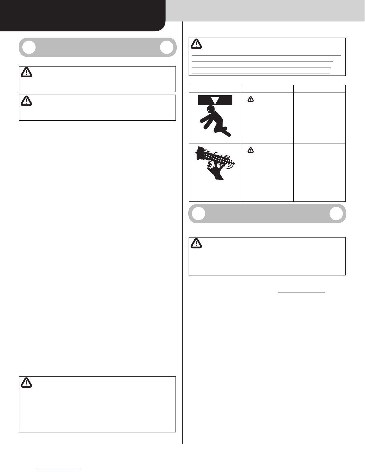
WARNING
DO NOT USE SLEEVE ANCHORS ON HOLLOW BLOCK.
FOR 2” TRACK: Tighten fasteners, securing the bottom jamb bracket in the vertical track
assemblies / bottom slot in the wall angle to jamb, maintain 3/8” to 5/8” spacing, between
the bottom section and vertical track.
FOR 3” TRACK: Tighten fasteners, securing the bottom jamb bracket in the vertical track
assemblies / bottom slot in the wall angle to jamb, maintain 1/2” to 3/4” spacing, between
the bottom section and vertical track.
Allow proper clearance as shown and use the values as illustrated in the Side Room Require-
ments (Minimum Distance Required), located in the pre-installation section of this manual.
Hang counterbalance lift cable over flag angle / angle mount. Repeat same process for other
side.
Stacking Sections
15
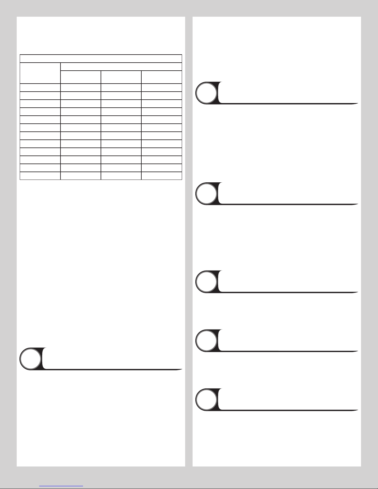
NOTE: Refer to door section identification, located in the pre-installation section of this
manual to determine what size sections you need to use as your lock (second) section, inter-
mediate (third) section, intermediate (fourth) section, intermediate (fifth) section, intermediate
(sixth) section, intermediate (seventh) section, intermediate (eighth) section and top section.
Measure your sections to make sure they are the correct height as indicated on the chart.
NOTE: Make sure graduated end and center hinges are flipped down, when stacking another
section on top.
Place appropriate stem track rollers into graduated end hinges of remaining sections.
NOTE: Larger doors will use long stem track rollers with double graduated end hinges.
With assistance, lift second section and guide the track rollers into the vertical tracks. Lower
section until it is seated against bottom section.
NOTE: Make sure graduated end and center hinges are flipped down, when stacking another
section on top.
With assistance, lift second section and guide the track rollers into the vertical tracks. Lower
section until it is seated against bottom section. Flip hinges up. Fasten center hinge(s) first;
then end hinges last using 1/4” - 14 x 7/8” self-drilling screws. Repeat same process for
other sections, except top section.
IMPORTANT: PUSH & HOLD THE HINGE LEAFS SECURELY AGAINST THE SECTIONS WHILE
SECURING WITH 1/4” - 14 X 7/8” SELF-TAPPING SCREWS. THERE SHOULD BE NO GAP
BETWEEN THE HINGE LEAFS AND THE SECTIONS.
NOTE: Install lock at this time (sold separately). See optional installation step, Side Lock.
Stacking Top Section
16
Place the top section in the opening. Install a nail to prevent the top section from falling back-
wards. Now, flip up the hinge leaves, hold tight against section, and fasten center hinges first
and end hinges last (refer to step, Stacking Sections). Vertical track alignment is critical.
POSITION FLAG ANGLE OR ANGLE MOUNT FROM THE EDGE OF THE DOOR:
FOR 2” TRACK APPLICATIONS: 1-11/16” (43 mm) to 1-3/4” (44 mm) for smooth, safe
door operation.
FOR 3” TRACK APPLICATIONS: 2-3/16” (56 mm) to 2-1/4” (57 mm) for smooth, safe door
operation
Tighten the bottom lag screw. Flag angles / Angle mount must be parallel to the door sec-
tions. Repeat for other side.
FOR 2” TRACK APPLICATIONS: Door width plus 3-3/8” (86mm) to 3-1/2” (89 mm) for
smooth, safe door operation.
FOR 3” TRACK APPLICATIONS: Door width plus 4-7/8” (124mm) to 5” (127 mm) for
smooth, safe door operation.
Complete the vertical track installation by securing the fasteners to the jamb. Push the verti-
cal track against the track rollers so that the track rollers are touching the deepest part of the
curved side of the track; tighten all the track bolts and nuts. Repeat for other side.
Attaching Drawbar Operator Bracket
17
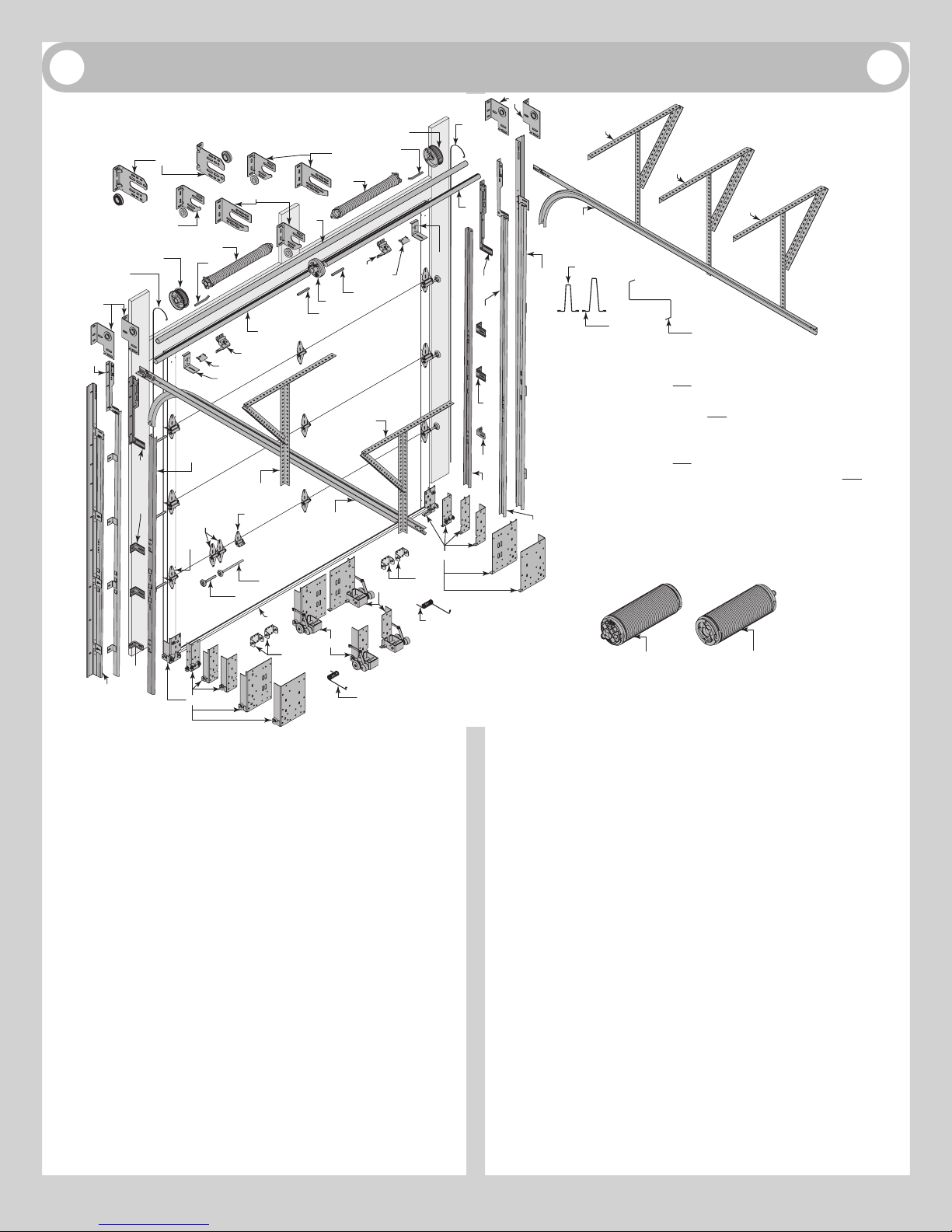
NOTE: If you don’t have a drawbar operator bracket, then skip this step. Refer to Illustrations
shown below, Package Contents or Breakdown of Parts, to determine which drawbar operator
bracket you have.
NOTE: If you’re installing a drawbar operator, the drawbar operator bracket must be mounted
and secured prior to installing top section.
IMPORTANT: WHEN CONNECTING A TROLLEY TYPE GARAGE DOOR OPENER TO THIS DOOR,
A WAYNE DALTON OPERATOR / TROLLEY BRACKET MUST BE SECURELY ATTACHED TO
THE TOP SECTION OF THE DOOR IF ONE HAS BEEN PROVIDED, ALONG WITH ANY STRUTS
PROVIDED WITH THE DOOR (IF A WAYNE DALTON OPERATOR / TROLLEY BRACKET WAS NOT
PROVIDED WITH YOUR DOOR, THAN USE THE ONE PROVIDED BY YOUR OPERATOR MANU-
FACTURER). THE INSTALLATION OF THE OPERATOR MUST BE ACCORDING TO MANUFAC-
TURER’S INSTRUCTIONS AND FORCE SETTINGS MUST BE ADJUSTED PROPERLY.
NOTE: For retro fit applications, the drawbar operator bracket must be aligned with an exist-
ing operator.
NOTE: Refer to illustrations to determine which drawbar operator bracket was supplied with
your door.
Place the bottom half of drawbar operator bracket inside the top half of drawbar operator
bracket and flush against the inside surface of the top section. Adjust both the top and bot-
tom halves out as far apart as possible on the section surface, as shown. Secure the bottom
half drawbar operator bracket and the top half drawbar operator bracket together using (4)
5/16” - 18 x 1/2” carriage bolts and (4) 5/16” - 18 flange hex nuts.
NOTE: Install the 5/16” - 18 x 1/2” carriage bolts and the 5/16” - 18 flange hex nuts as far
apart as possible, prior to securing both top and bottom halves together.
Now, locate the center of the top section and align the center of the holes in the drawbar op-
erator bracket assembly with the top section center line. Align the drawbar operator bracket
assembly vertically.
Slide the upper half of the drawbar operator bracket under the strut (if applicable), keeping
the drawbar operator bracket aligned with the center line. Remove the strut’s screws, if nec-
essary and attach to the top section (through strut if necessary) using 1/4” - 20 x 7/8” self
drilling screws. Attach the lower half of the drawbar operator bracket to the section surface
using 1/4” - 20 x 7/8” self drilling screws.
NOTE: When attaching drawbar operator bracket to top section with strut, apply additional
pressure to thread into the strut.
NOTE: Depending on your door width, it may be required that the rectangular drawbar
operator bracket be mounted off center so the drawbar operator bracket mounts to the hinge
points.
Now, locate the center of the top section and align the drawbar operator bracket assembly
with the top section center line. Align the drawbar operator bracket assembly vertically and
horizontally. Secure the drawbar operator bracket to the top section surface using 1/4” - 20 x
7/8” self drilling screws, as shown. Next, if applicable and using 1/4” - 20 x 7/8” self drilling
screws, secure the rectangular drawbar operator bracket to the Strut / C Channels, as shown.
Attaching Horizontal Tracks
18
NOTE: Depending on your door, you may have Fully Adjustable Flag Angles, Riveted Vertical
Track Assemblies or you may have Angle Mount Vertical Track Assemblies. Refer to Package
Contents / Breakdown of Parts, to determine which Flag Angles / Vertical Track Assemblies
you have.
WARNING
DO NOT RAISE DOOR UNTIL HORIZONTAL TRACKS ARE SECURED AT
REAR, AS OUTLINED IN STEP, REAR BACK HANGS, OR DOOR COULD FALL
FROM OVERHEAD POSITION CAUSING SEVERE OR FATAL INJURY.
IMPORTANT: PRIOR TO INSTALLING THE HORIZONTAL TRACKS, USE CABLES OR CHAINS TO
TEMPORARILY SUSPEND THE REAR PORTION OF HORIZONTAL TRACKS.
WARNING
DO NOT USE ROPES, SINCE EDGES OF HORIZONTAL TRACKS AND
ANGLES ARE VERY SHARP.
IF YOU HAVE FLAG ANGLES: To install horizontal track, place the curved end over the top
track roller of the top section. Align the bottom of the horizontal track with the top of the verti-
cal track. Tighten the horizontal track to the flag angle with (2) 1/4” - 20 x 9/16” track bolts
and (2) 1/4” - 20 flange hex nuts.
IF YOU HAVE ANGLE MOUNT: To install horizontal track, place the curved end over the
top track roller of the top section. Align the bottom of the horizontal track with the top of the
vertical track. Tighten the horizontal track to the angle mount with (2) 1/4” - 20 x 9/16” track
bolts and (2) 1/4” - 20 flange hex nuts.
Next level the horizontal track assembly and bolt the horizontal track angle to the first
encountered slot in the flag angle / angle mount using (1) 3/8” - 16 x 3/4” truss head bolt
6