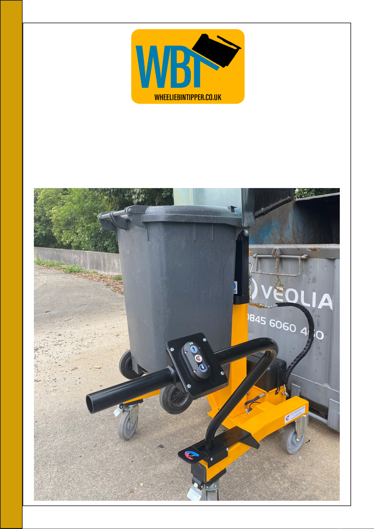
WBT SUMO UNI LIFT Instruction Manual

SUMO UNI LIFT USER AND
SAFETY MANUAL

Contents
1- Contents
2- Key features of the Uni Lift Machine
3- Overview drawings
4- Machine dimensions and weight
5- Uni Lift Safety
6- Recommended Precautions
7- Uni Lift Safety labels for operation and PPE
8- Uni Lift Operating Instructions
10- Battery Charger manual
16- Daily and Monthly checks
17- Exploded view and parts list
18- Hydraulic system
19- Hydraulic power pack
21- Hydraulic schematic
22- Hydraulic cylinders
23- Electronic control
25- Wiring loom
26- Moving and storage
27- Certificate of Conformity
1

Key Features of the Sumo Uni Lift System
1- Very heavy duty construction with low centre of gravity giving incredible
stability
2- High quality castors allow the machine to be easily manoeuvred into position even
on rough terrain.
3- Independent lift and tip functions allow the operator to select the exact tip height
required to suit the skip or bin.
4- Huge weight capacity of up to 150 kg
5- Unique electronic push button control system allows easy control for the
operator and electronically provides safety interlocks to prevent accidental
operation and to position the operator away from the bin during the lift and tip cycle.
The electronic control pad is also fitted with a battery strength LED
indicator which shows green when the battery is fully charged, yellow when at half
charge and red when at 10% charge
6- Low maintenance machine pivot points and sliding parts fitting with either composite
bearings or sealed roller bearings.
7- Unique bin clamping system allows different sizes of bins to be handled on one
machine.
Construction
1- The Uni Lift is made up of a steel fabricated base frame a telescopic mast and a
tipping cradle along with a tubular steel control arm which rotates thru 90
degrees from the travel position to the operational position.
2- The hydraulic system comprises of 3 hydraulic cylinders, power pack and
battery.
Mechanism
1- When operated the telescopic mast can be raised and lowered independently via the
main mast cylinder and power pack to the height required and the tipping cradle can be
rotated independently via the power pack and electronic control system.
Assembly
1- The Unit lift is supplied fully assembled and tested ready for use.
2

Overview Drawings
3

Machine Dimensions And Weight
Machine Weight: 200KG
4

Uni Lift Safety
The Sumo Uni Lift has been designed with user safety as priority, without reducing
its capability or ease of use.
We recommend that a comprehensive hazard and risk assessment is carried out
prior to the Uni Lift being used for the first time.
This machine should not be operated by anyone who has had no training or has
not read the user manual thoroughly.
This machine should not be used to carry fully laden bins, this machine is
designed to be positioned in an appropriate place with the foot brake applied
safely and the wheelie bin should be brought to it.
The Uni Lift has a number of safety features listed below:
1- The control arm has 2 positions, the first is to allow the machine to be moved
around allowing the operator to have good control, with the arm in this position
the controls will not operate so the hydraulic system will not function. To rotate the
control arm the operator must physically lift the latching plate this will then allow
the control arm to rotate thru 90 degrees. Once in position the latching plate drops
back into place locking the control arm in position the controls can now be
activated. The rotation of the control arm removes the operator from harm whilst
the bin is being tipped.
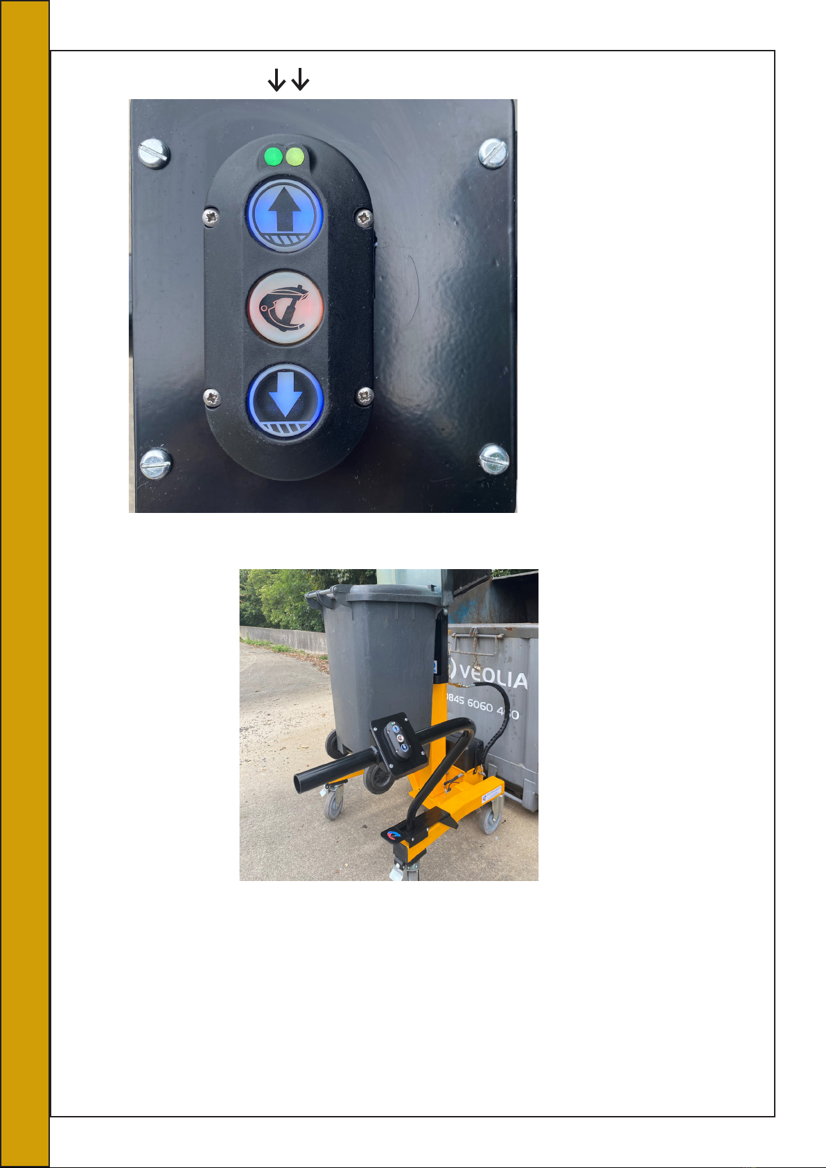
2- To activate the electronic controls the centre button must be pressed 3 times in
quick succession this will bring the control pad to life. To operate the system
follow the operating instructions on page 8. If the machine is left unattended for
more than 10 seconds the electronic controls will automatically switch off. All the
buttons on the control pad are momentary so when released the machine will
automatically stop.
3- When the hydraulic system is in operation an audible beeper is also activated
simultaneously to warn anyone nearby that the machine is in operation.
4- The footprint of the machine combined with the low centre of gravity ensure
that the machine remain stable throughout the tipping cycle.
5- Pressure compensated flow control cartridges ensure that during the lowering
cycle the machine is always under control even when handling a fully laden bin.
5

Reccomended Precautions
-Only trained and authorised operators should be permitted to use the machine
-Operators must read and obey the instructions displayed on the machine
-Never operate machine on uneven ground or a ramp
-Never operate machine on the edge of a raised dock or platform
-Never operate machine with any covers or gaurds removed
-Anyone other than the operator must keep 2 meters clear of the machine whilst
it is in operation
-Always keep hand and feet clear of bin and cradle when operating
-Do not empty bins if over filled
-Before connecting machine to mains supply, ensure voltage and frequancys
correspond with thats listed on the range plate
-Do not use extension leads to connect machine to mains supply
-Do not operate if power supply lead and insulation is damaged
-Do not connect a damp power plug or socket
-Ensure the supply socket is fitted with a residual current device
-Ensure there is complete continuity between the machine and an effective
earthing
6

Uni Lift Safety Labels For Operation And PPE
All Safety stickers are clearly mounted on the machine in clear view. Please
ensure the correct PPE is being used before operating the machine.
7

Operating Instructions
Before Operation
1- This machine should only be operated by authorised personnel
2- Ensure the machine is on stable and level ground
3- Ensure there are no overhead obstructions
4- Ensure both foot brakes have been applied
5- Ensure that all personnel other than the operator are well clear of the machine
6- Ensure the tip cradle is fully lowered
To empty bins / containers
1- Once the machine is in position lift the foot oparated arm release and
rotate the operator pendant into the control position
2- Place the bin / container against the tip cradle ensuring its positioned
correctly
8

3- Press the centre button 3 times to energise the electrical system
4- Press the raise button until the bin is at the height required
5- Press the raise and centre buttons simultaneously to activate the tip
function
6- Once the bin / container is empty press the lower button until the bin is on the
ground
7- Remove the bin and repeat as required.
NOTE! The lift and tip operations can be stopped at any time by simply releasing
the buttons
Raise
Central Button
Lower
On Light Battery Strenght Indicator
9

Battery Charger Manual
10

11

12

13

14

15

Sumo Unit-Lift inspection schedule
Daily Checks
1- Visually check that there is no damage to the base frame, telescopic mast and
tipping cradle
2- Check the condition of the castors and ensure foot brakes are working
3- Check battery is fully charged
4- Check hydraulic hoses and connectors for any leaks
Monthly Checks
1- Check battery and battery charger and cables and connections to ensure they
are all in good condition.
2- Check that all warning and safety labels are legible
3- Check the bolts holding the castors are tight
4- Check the operation of the telescopic mast by raising it to full height and
lowering
5- Spray inner mast with white grease with PTFE
6- Check the operation of the tipping cradle and bin clamp mechanism by
operating with an empty bin
Yearly Maintenance
1- Replace hydraulic oil in the power pack
2- Check for any damaged or worn parts, refer to parts list on page 17
16

Exploded View And Parts List
17

Hydraulic System
•The power pack consists of a 0.8KW 12vDC motor close coupled to a 0.8cc gear
pump with a 2L oil tank, the control valves are integrated into the power pack
manifold. See attached drawing on page 19
•The hydraulic valves consist of 3 solenoid directional controls, 2 independent
relief valves and 2 pressure compensated flow controls. See attached schematic on
page 21
•The uni lift uses 3 hydraulic cylinders, 1 main mast cylinder to raise and lower the
mast and 2 tip cylinders which rotate and tip the cradle but also interact with the
locking bar to hold the bin onto the cradle during the tipping cycle. See drawing
630.800 for mast cylinder and 625/3 for tip cylinders on page 22
•Maintenance – the system will require an oil change every 12 month or after 500
hours run time, we recommend a high grade 46st mineral oil is used. Please
dispose of waste oil carefully and follow environmental laws.
•Spares – seal kits for both models of hydraulic cylinder are available and spares
valves and starters for the power pack
181
18

Hydraulic Power Pack
19
Table of contents
Popular Trash Compactor manuals by other brands

Broan
Broan Elite 15XEBL Specification sheet

Whirlpool
Whirlpool GX900QPLQ - 15" Trash Compactor Use and care guide

Displays2go
Displays2go “THANK YOU” DUAL Assembly instructions

NuTone
NuTone 1055 Specification sheet

Cucine Oggi
Cucine Oggi MEGA 40 Assembly instructions

Broan
Broan Elite 15XEWH Service manual