disperator 8075-E Original operating manual

DISPERATOR AB Mälarvägen 9, SE-141 71 Segeltorp, SWEDEN Ref: Serv-8075/Eng/140301
Tel: +46 8 724 01 60, Fax: +46 8 724 60 70
E-mail: info@disperator.se, Web page: www.disperator.se
Service Instruction
for
Trash Compactor Model 8075-E
Motor 220-240V, 50/60Hz
140227B

2
3
Safe Servicing Practices
To avoid personal injury and/or property damage, it is important that Safe Servicing Practices be observed.
The following are some limited examples of safe practices.
1. DO NOT attempt a product repair if you have any doubts as to your ability to complete it in a safe
and satisfactory manner.
2. Before servicing or moving an appliance, remove the power cord from the electrical outlet, trip the
circuit breaker to the OFF position, or remove the fuse.
3. Never interfere with the proper operation of any safety device.
4. USE ONLY REPLACEMENT PARTS CATALOGED FOR THIS APPLIANCE. SUBSTITUTIONS MAY
DEFEAT COMPLIANCE WITH SAFETY STANDARDS.
5. GROUNDING: The standard color coding for safety ground wires is GREEN, or GREEN WITH
YELLOW STRIPES. Ground leads are not to be used as current-carrying conductors. It is EXTREMELY
important that the service technician re-establish all safety grounds prior to completion of service.
Failure to do so will create a hazard.
6. Prior to returning the product to service, ensure that:
• All electrical connections are correct and secure
• All electrical leads are properly dressed and secured away from sharp edges, high-temperature
components, and moving parts
• All non-insulated electrical terminals, connectors, heaters, etc., are adequately spaced away from
all metal parts and panels
• All safety grounds (both internal and external) are correctly and securely connected
• All panels are properly and securely re-assembled
NOTE
This service manual is intended for use by persons having electrical and mechanical training and
a level of knowledge of these subjects considered acceptable in the appliance repair trade.
DISPERATOR cannot be responsible, or assume any liability, for injury or damage of any kind
arising from the use of this manual.
Grounding Instructions
IMPORTANT: TO REDUCE THE RISK OF ELECTRIC SHOCK - PLEASE READ CAREFULLY.
FOR PERSONAL SAFETY, THIS APPLIANCE MUST BE PROPERLY GROUNDED.
IF THERE IS ANY DOUBT AS TO WHETHER THE WALL RECEPTACLE IS PROPERLY GROUNDED,
HAVE IT CHECKED AND PROPERLY GROUNDED BY A QUALIFIED ELECTRICIAN.
A 220-240 volt, 50-60 Hz., A.C., 10 amp fused and grounded electrical supply is required (time-delay
fuse or circuit breaker is recommended). It is recommended that a SEPARATE CIRCUIT serving only this
appliance be provided.
DO NOT USE AN EXTENSION CORD OR PLUG ADAPTER WITH THIS APPLIANCE.
NOTE

2
3
Table of contents
Safe Servicing Practices .......................................... 2
Grounding Instructions ............................................ 2
Features ..................................................................... 4
Section A – Installation ............................................ 5
Free-Standing ............................................................. 5
Built-In Installation ...................................................... 5
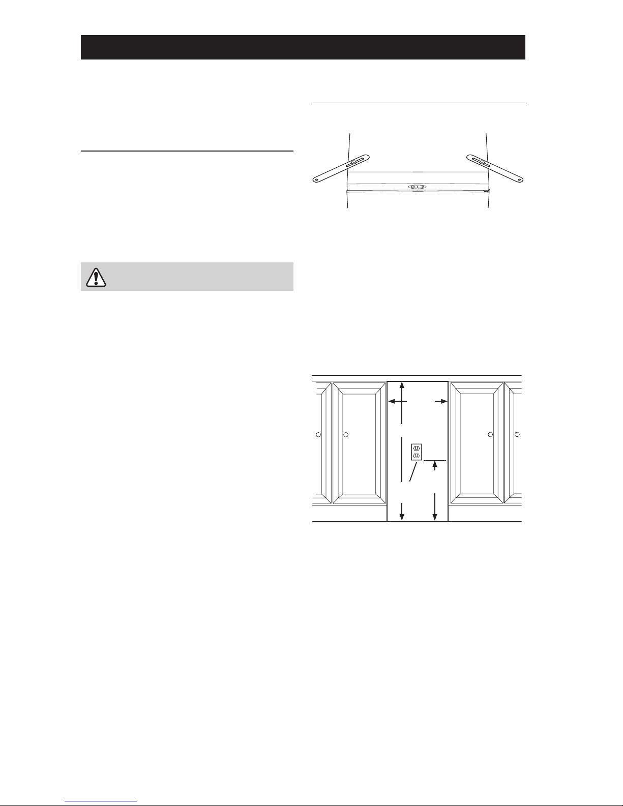
Mounting Straps .................................................... 5
Under-Counter Opening ........................................ 5
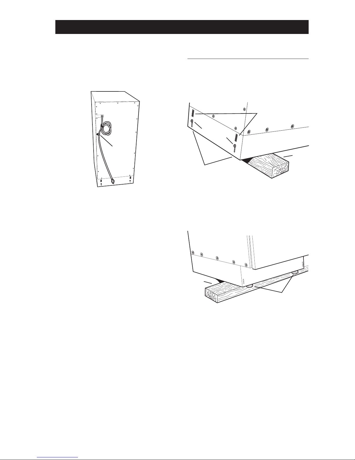
Cord Clamp ............................................................ 6
Leveling the Compactor ............................................. 6
Section B – Cabinet .................................................. 7
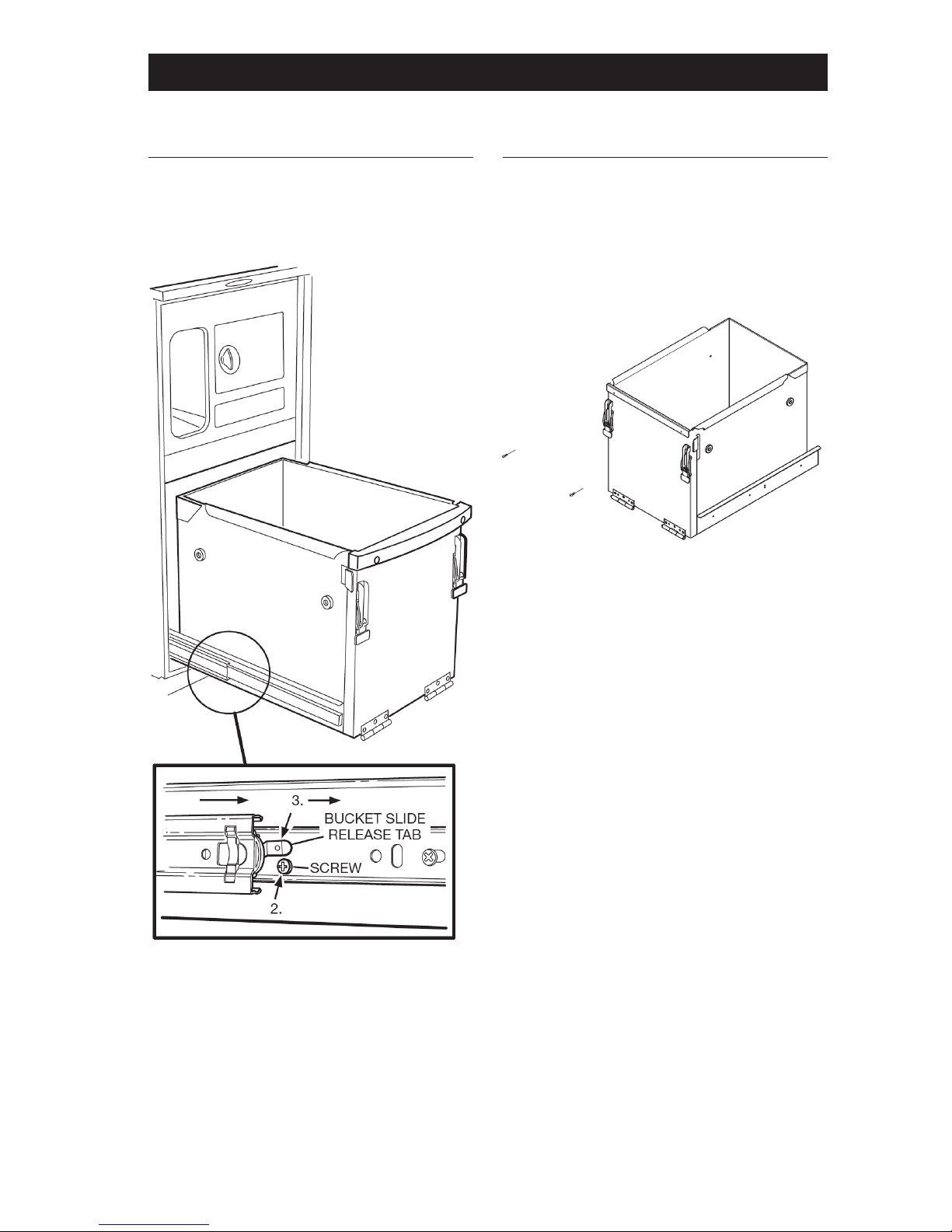
Trash Bucket ............................................................... 8
Remove .................................................................. 8
Bucket Handle . ........................................................... 8
Remove and Replace . ............................................ 8
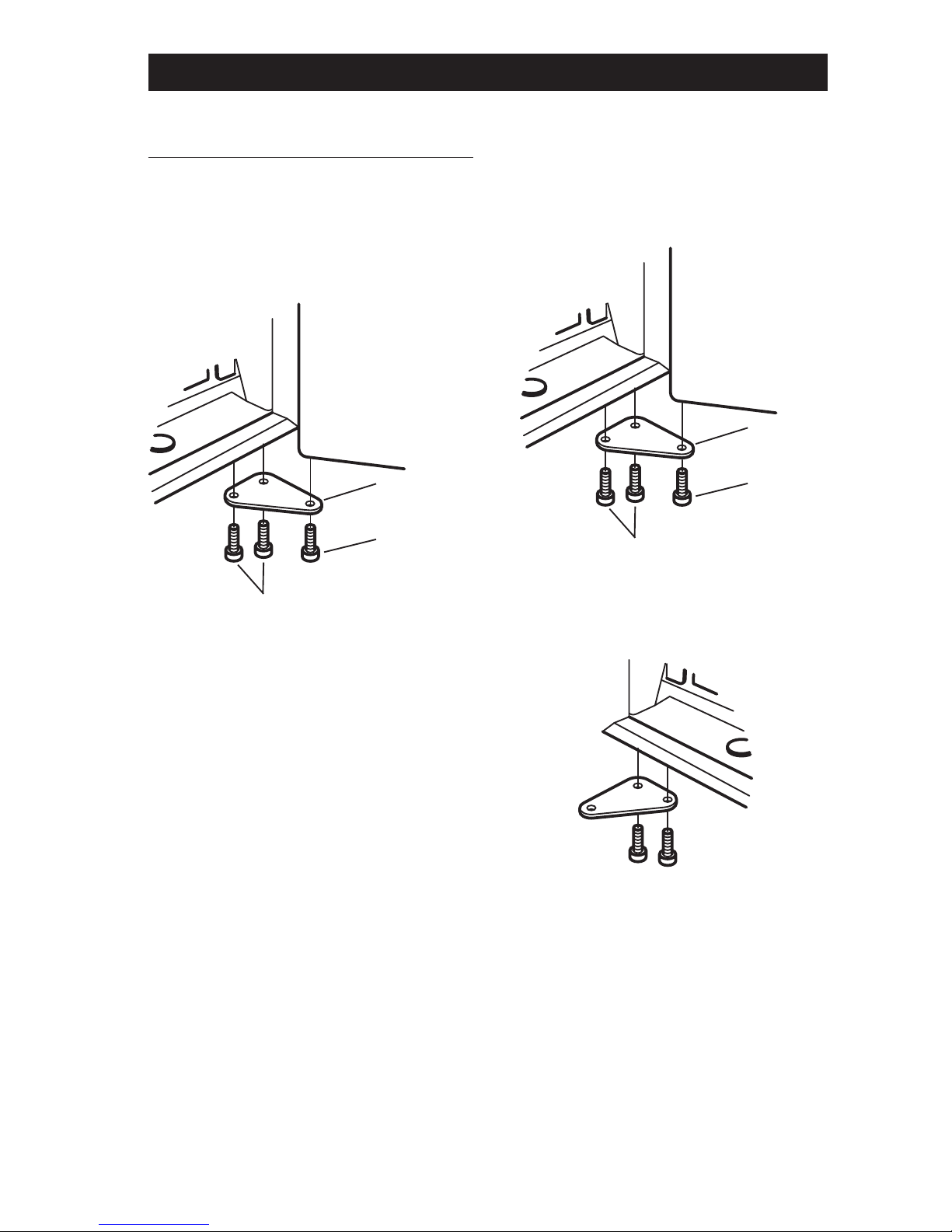
Slide Rails (Cabinet) .................................................... 9
Remove and Re-install . .......................................... 9
Slide Rails (Bucket) . .................................................... 9
Remove and Re-install . .......................................... 9
Door Assembly ......................................................... 10
Remove and Re-install . ........................................ 10
Reverse Door Hinge Position . .............................. 10
Safety Interlock Actuator .......................................... 11
Remove and Re-install . ........................................ 11
Gasket Assembly ...................................................... 12
Remove and Re-install . ........................................ 12
Top Trim Cover Assembly ......................................... 13
Remove and Re-install . ........................................ 13
Section C – Power Unit Mechanism ..................... 14
Drive Belt .................................................................. 15
Remove and Re-install ......................................... 15
Main Motor ............................................................... 16
Remove and Replace ........................................... 16
Complete Power Unit Mechanism ............................ 17
Remove and Re-install ......................................... 17
Drive Wheels ............................................................. 17
Remove and Replace ........................................... 17
Ram Screw Assembly .............................................. 18
Remove and Replace . .......................................... 18
Section D – Electrical Components ...................... 21
Start Switch .............................................................. 22
Remove and Replace ........................................... 22
Access to Components ............................................ 22
Remove Cabinet Cover ........................................ 22
Re-install Cabinet Cover ...................................... 24
Control Panel Assembly ........................................... 25
Remove and Re-install ......................................... 25
Display Module Assembly ........................................ 26
Remove and Re-install ......................................... 26
Key Switch ................................................................ 26
Remove and Replace . .......................................... 26
Interlock Switch Assembly ........................................ 27
Remove and Re-install ........................................ 27
Upper Limit Switch Assembly ................................... 27
Remove and Replace ........................................... 27
Lower Limit Switch ................................................... 28
Remove and Replace ........................................... 28
Motor Centrifugal Switch Assem .............................. 28
Remove and Replace ........................................... 28
Motor Capacitor ....................................................... 29
Test, Remove and Replace .................................. 29
Section E – Troubleshooting
Troubleshooting Table ............................................... 31
Section F – Specifications
Specifications Table .................................................. 34
Section G – Diagrams and Parts Lists
Wiring Schematic ..................................................... 34
Drawing and Parts List – Cabinet ............................. 35
Drawing and Parts List – Mechanism ....................... 36
Table of Contents

4
5
How the compactor works
The compactor compresses kitchen trash up to 1/6 of its original volume. It will compact normal kitchen trash
including cartons, glass and plastic bottles, containers and jars, tin cans, wrappings, boxes etc.
When you start the compactor, an electrically powered ram moves down into the trash bucket, compresses the
trash and then returns to the “UP” position and shuts off automatically.
NOTE: The ram travels about 2/3 of the way down into the trash bucket. Because of this, the trash bucket must be
at least 1/3 full before you will notice any compression.
ELECTRICAL
COMPONENTS
(SECTION D)
POWER UNIT
MECHANISM
(SECTION C)
CABINET
(SECTION B)
Features

4
5
Your compactor has been designed to require
minimum space without loss of capacity whether
free-standing or built-in.
Free-Standing
As shipped, the compactor is only configured for
built-in installations. This appliance can be converted
from built-in to free-standing with the use of Toe Kick
Accessory Kit Model 15TCTK (sold separately).
If additional cord length is required for free-standing
installation, remove the cord clamp and wire tie on the
back of the unit.
CAUTION
Failure to use Toe Kick Assembly Kit Model 15TCTK
in a free-standing installation may cause the
compactor to be unstable during operation.
Section A – Installation
Built-in Installation
MOUNTING STRAPS
Two under-counter mounting straps are provided. Use
these straps to secure the compactor to the underside
of a countertop.
Fasten the slotted end of the straps to the compactor
using the holes in the top of the compactor cabinet as
shown.
NOTE: When installation compactor under granite or
solid surface countertops, bend the mounting straps
so they can be secured to the adjacent cabinetry.
UNDER-COUNTER OPENING
The compactor requires an under-counter opening 15-in.
wide, 34-1/2-in. high, and 22-in. deep.
Plan to provide an electrical outlet in the opening that
meets all applicable electrical codes and requirements.
See “Grounding Instructions” on Page 2 for specific
information.
TOP OF
COMPACTOR
FRONT OF
COMPACTOR
Opening
15" Wide
34-1/2" High
22" Deep
15" W
341/2" H
22" D
12" MIN
ELECTRICAL
OUTLET
CAUTION

6
7
Section A – Installation
CORD CLAMP
The compactor is equipped with a 6-ft. long power
cord. Use the cord clamp to prevent excess power
cord from being pinched beneath the cabinet during
installation or service.
Leveling the Compactor
Your compactor has four adjustable levelers; (2) rollers
in the rear and (2) legs in the front. They allow you to
adjust for uneven floors and also trim the unit up to fit
an undercounter installation.
To level the back of the compactor:
Tip the back of compactor up and onto a wood block.
Loosen the adjusting screws only far enough to move
the rollers to a higher or lower slot. Retighten the ad-
justing screws and remove the wood block.
To level the front of the compactor:
Tip the front of compactor up and onto a wood block.
Turn the leveling legs in or out to the desired position.
Remove the wood block.
CORD
CLAMP
BACK OF
COMPACTOR
WOOD
BLOCK
ADJUSTING
SCREWS
SLOTS
ROLLERS
FRONT OF
COMPACTOR
WOOD
BLOCK
LEVELING
LEGS

6
7
Cabinet
The compactor’s main cabinet supports and encloses
a number of sub-assemblies. These include the trash
bucket, the door, the motor, the ram, and the electrical
controls and components.
Section B – Cabinet
Legend
A. Trash Bucket
B. Bucket Handle
C, D. Slide Rails
E. Door Assembly
F. Safety Interlock Actuator
G. Gasket Assembly
H. Top Trim Cover
ABC, D
FG E
H

8
9
Section B – Cabinet
Trash Bucket
REMOVE
To remove the bucket completely from the cabinet for
repairs or cleaning, follow these instructions.
1. Pull out trash bucket until it stops.
2. Remove one screw from each of the bucket slides
3. Press down on left and right bucket slide release
tabs while pulling the bucket out of the cabinet.
Buckle Handle
REMOVE AN REPLACE
The plastic bucket handle may receive a lot of ‘‘wear
and tear” simply because the operator uses it every
time he or she places trash in to the compactor,
or removes or replaces the bag. If the handle is
scratched, chipped or broken, replace it.

8
9
Slide Rails (Cabinet)
REMOVE AND RE-INSTALL
The compactor’s slide rails may become bent from
misuse or the ball bearings may become worn.
1. Remove trash bucket assembly. (See Trash Bucket,
Remove.)
2. Remove two Phillips head screws from the front and
rear of the left track slide rail. NOTE: It is necessary
to slide the inner rail to access both screws.
3. Remove the slide rail from the cabinet.
4. To re-install, place slide rail onto the three “spring
clips” inside of the cabinet. Align holes in rail with
bracketed holes on inside of cabinet and secure
with two Phillips head screws. Repeat for other side.
Slide Rails (Bucket)
REMOVE AND RE-INSTALL
1. Remove four Phillips head screws that secure the
left slide rail to the bucket. Remove the rail.
2. Repeat Step 1 for the right slide rail.
3. Installation is the reverse of removal.
Section B – Cabinet
RAIL
SPRING CLIPS
SCREW
NUT
SCREWS
RAIL
BUCKET
SCREW
SCREWS

10
11
Door Assembly
REMOVE AND RE-INSTALL
The heavy-duty door could become dented, scratched
or bent and require replacement. Door removal is also
necessary for some service procedures.
IMPORTANT: Firmly support the door during removal
and re-installation.
1. With the door closed, use a 3/16” allen wrench to
remove the lower hinge pin.
2. Carefully remove door by opening and sliding the
bottom of the door away from the cabinet.
3. To re-install, lift the door, insert the upper hinge pin
into the upper door bushing and move the door into
place. Insert the lower hinge pin from Step 1 and
tighten securely.
Section B – Cabinet
REVERSE DOOR HINGE POSITION
The compactor comes from the factory with the door
in the right-hand opening position. Use the following
instructions to reverse the door.
1. Remove the door (see Remove and Re-install).
2. Use a 3/16” allen wrench to remove the lower hinge
pin from the cabinet (2 screws).
3. Turn the bracket over and install the bracket on the
opposite side of the cabinet using the same screws.
SCREWS
DOOR
LOWER
HINGE
BRACKET
LOWER
HINGE
PIN
SCREWS
DOOR
LOWER
HINGE
BRACKET
LOWER
HINGE
PIN

10
11
4. Use a screwdriver to remove the upper hinge pin
from the trim piece and re-install the pin on the
opposite side.
5. Being careful not to scratch the door, remove the
plastic door bushing and cap from the top and
bottom of the door using a small flat screwdriver.
Install the bushings on the side of the door panel
that will be hinged and install the caps on the
opposite side.
6. Re-install the door (see Remove and Re-install).
Safety Interlock Actuator
REMOVE AND RE-INSTALL
This safety device prevents the compactor from ope-
rating except when the door is closed. NOTE: If the
interlock actuator should break off, the compactor will
not function; replace it promptly.
1. Remove the 14 Phillips head screws from the inner
door panel. Remove panel and set aside.
2. Remove insulation pad from door.
3. Remove Phillips head screw from inside of door
panel and remove actuator.
4. Installation is the reverse of removal. NOTE: Fully
seat actuator in the door panel before re-installing
screw.
Section B – Cabinet
BUSHING
CAP
DOOR
UPPER
HINGE
PIN
TRIM PIECE
DOOR
INSULATION
PAD
INNER DOOR
PANEL
14
SCREWS
ACTUATOR
SCREW

12
13
Gasket Assembly
REMOVE AND RE-INSTALL
The gasket is made of a flexible vinyl material with
imbedded magnets. Over time it may become brittle or
cracked, and lose its flexibility. If this happens the door
may not close properly, so replace the gasket.
1. Remove door assembly (see Door Assembly,
Remove and Re-install).
2. Remove control panel (see Electrical Components,
Control Panel Assembly).
3. Lift the outer edge of the gasket to expose the
retainer strips and the screws that are used to
fasten the strips to the cabinet. NOTE: There are six
retainer strips: two each on the top and bottom and
one each for the left and right sides.
4. Remove the Phillips head screws that secure the
retainer strips to the cabinet; then remove the strips
from underneath the gasket. Pull the gasket off of
the cabinet.
5. To install a new gasket, place retainer(s) under the
outer edge of the gasket, then use the screws to
fasten the retainers and gasket to the cabinet.
6. Re-install the control panel.
Section B – Cabinet
CABINET
GASKET
RETAINER
STRIPS
SCREWS
TRIM
COVER

12
13
Top Trim Cover Assembly
REMOVE AND RE-INSTALL
1. Remove the door (see Door Assembly, Remove and
Re-install).
2. Remove the four Phillips head screws that secure
the top trim cover to the cabinet.
3. Pull the top trim cover away from the cabinet.
4. Re-install in reverse order. Be careful not to
overtighten screws.
Section B – Cabinet
SCREWS

14
15
Legend
A. Drive Belt
B. Main Motor
C. Complete Power Unit Mechanism
D. Ram Screw Assembly
Section C – Power Unit Mechanism
B
D
C
A

14
15
Drive Belt
REMOVE AND RE-INSTALL
The drive belt transfers power from the motor to the ram
screws. If it requires replacement, follow these steps.
1. Remove cabinet cover (see Electrical Components,
Access to Components).
2. Remove the four Phillips head screws that secure
the belt cover to the unit.
3. Use a 5 mm hex wrench to loosen the three hex
head cap screws. Rotate motor to loosen belt for
removal.
IMPORTANT: Before installing a new drive belt, follow
the instructions below to align the height of both ram
screws.
4. Measure the distance from the underside of the top
frame to the bottom edge of the ram at the front and
rear of the power unit.
5. If the measurements are different, rotate the
ram screw drive wheels as necessary until the
measurements match.
6. Install new belt, making sure it seats properly in gear
teeth. Adjust the belt tension by rotating the motor
until the belt deflection is 1/2 inch. Tighten the three
hex head cap screws securely. Re-install the belt
cover.
Section C – Power Unit Mechanism
BELT
COVER
BELT
4 COVER
SCREWS
3 MOTOR
SCREWS
SCREWS
CAP SCREWS
DRIVE WHEELS
TOP FRAME
RAM

16
17
Main Motor
REMOVE AND REPLACE
Follow these instructions if it becomes necessary to
replace the main motor.
1. Remove cabinet cover (see Electrical Components,
Access to Components).
2. Remove the belt cover and drive belt (see above)
and follow the steps in Drive Belt, Remove and Re-
install.
3. Mark the location of all wire connections and ties on
the motor, then disconnect the wires.
NOTE: For illustration purposes, the view is shown with
the drive wheels removed.
4. Use an open-end, socket or crescent wrench to
remove the idler wheel.
5. Support the motor from underneath and remove
the three head cap screws, lock washers and flat
washers. Remove the motor.
6. Re-assemble in reverse order. Adjust the belt
tension by rotating the motor until the belt deflection
is 1/2 inch.
Section C – Power Unit Mechanism
DRIVE
WHEEL
MOTOR
IDLER
WHEEL
IDLER
WHEEL
3 HEAD CAP SCREWS,
LOCK WASHERS AND
FLAT WASHERS

16
17
Complete Power Unit Mechanism
REMOVE AND RE-INSTAL
The complete power unit mechanism consists of the
ram screw assemblies, the motor and the drive belt.
Rather than replace individual components, it may be
easiest to replace the whole mechanism.
1. Remove cabinet cover (see Electrical Components,
Access to Components).
2. Mark the location of all wire ties. screws
3. Support the power unit and remove the two Phillips
head screws from each of four support rods.
4. Remove the power unit mechanism.
5. Installation is the reverse of removal.
Drive Wheels
REMOVE AND REPLACE
1. Remove cabinet cover (see Electrical Components,
Access to Components).
2. Remove the belt cover and drive belt (see above)
and follow the steps in Drive Belt, Remove and Re-
install.
3. Remove spring washer, bearing and thrust washer
from each drive wheel and remove both drive wheels.
NOTE: Grease the spring washer, bearing and thrust
washer before re-installing.
Section C – Power Unit Mechanism
SCREWS
SUPPORT
ROD
SCREWS
SPRING
WASHER
BEARING
THRUST
WASHER
DRIVE
WHEEL
IDLER
WHEEL
3 SCREWS
MOTOR

18
19
Ram Screw Assembly
REMOVE AND REPLACE
The ram screw assemblies transfer power to the ram
and plate. Heavy usage can damage the threaded rod.
If it becomes necessary to replace one or both of the
ram screw assemblies, follow the instructions below.
1. Remove cabinet cover (see Electrical Components,
Access to Components).
2. Remove the drive belt (see Drive Belt, Remove and
Re-install).
3. Remove drive wheels (see Drive Wheels, Remove
and Replace).
4. Remove the compaction plate by releasing the tab
on the front of the ram, and pulling the plate down
and away from the ram. Note: When re-installing the
plate, insert the rear tab into the slot at the rear of
the ram, then press up on the front of the plate until
it latches securely in place. 5. Remove the four hex head screws and the ram from
the bottom of the ram screw assembly.
Section C – Power Unit Mechanism
RELEASE
TAB
RAM
COMPACTION
PLATE
SCREWS
SCREWS
TAB
RAM
SCREW
ASSEMBLY
COMPACTION
PLATE
RAM

18
19
6. Remove two hex head screws, shims, brackets
and nuts (fasteners) from the top of the ram screw
assembly. Note orientation of bracket during
removal as they activate the limit switches.
7. Turn the ram until the top pin indexes 90° from the
pin slot; remove two hex screws, lock washers and
flat washers (fasteners).
8. Turn the ram as required to align the ram pin with
the slot in the top frame and lower the ram through
the hole.
Section C – Power Unit Mechanism
FASTENERS
PIN
FASTENERS
PIN
SLOT

20
21
9. Remove the pin, thrust washer, bearing, and upper
bearing housing from the ram.
10. Lower the ram screw assembly through the center
stabilizer plate.
IMPORTANT: On re-assembly, index the bosses on the
top bearing housing with the corresponding notches in
the bearing. Brackets must be positioned correctly as
they activate the limit switches. See illustration at left.
11. Re-assembly is the reverse of disassembly.
Section C – Power Unit Mechanism
NUT
BRACKETS
TOP
PIN
SCREW
BEARING
HOUSING
LOWER RAM
SCREW
HOUSING
BEARING
RAM
SCREW
THRUST
WASHER
STABILIZER
PLATE
THRUST
WASHER
BEARING
HOUSING
PIN BEARING
BOSSES NOTCHES
Table of contents
Other disperator Trash Compactor manuals