TEIL1
ALLGEMEINES
1.1.
MECHANISCHER
BETRIEB
in
diesem
Gerat
wird
die
Betriebsart
umgeschaltet,
indem
das
Pausenrad
oder
das
Begrenzerrad
in
das
Antriebsrad
(auf
dem
Schwungrad
befestigt)
eingreift.
1)
Schneller
Vorlauf/Schneller
Ricklauf
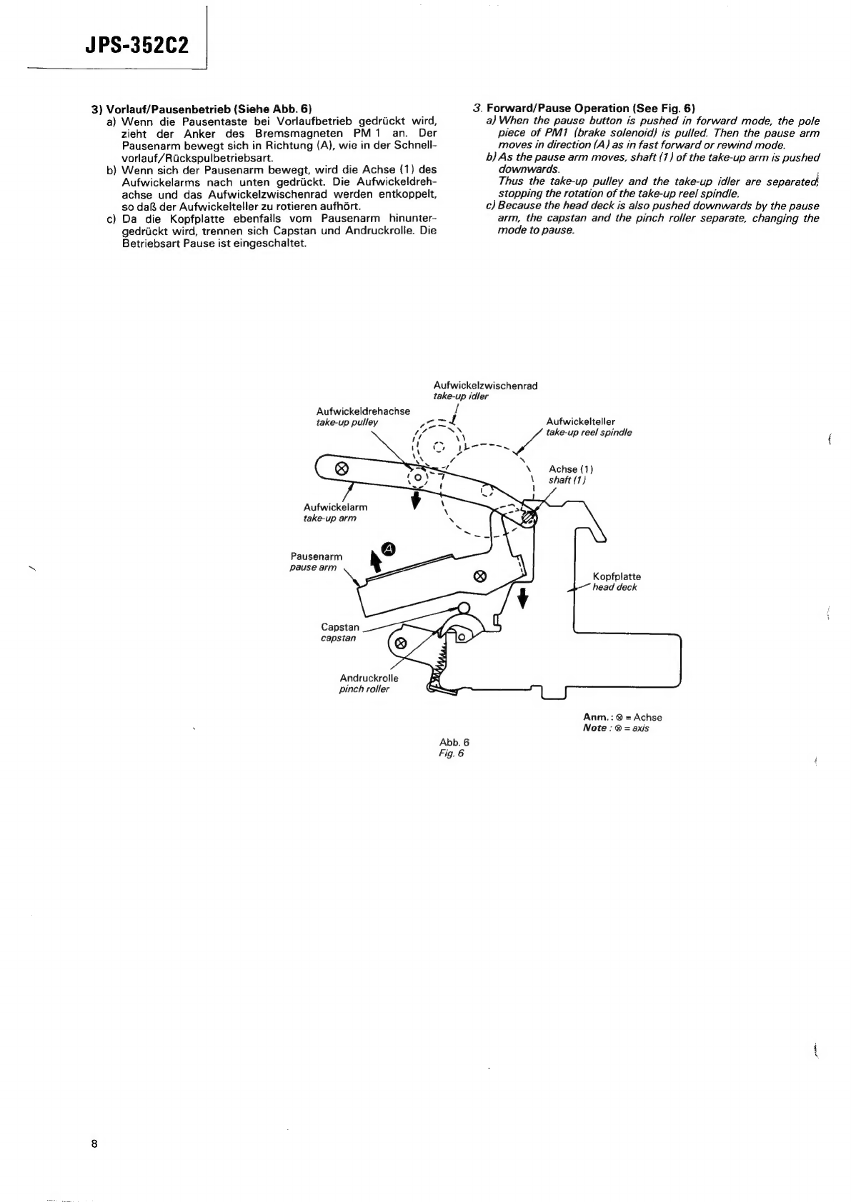
1.
Freigeben
der
Bremse
(Siehe
Abb.
1)
a)
Wird
die
Schnellvorlauf
—
oder
die
Ruckspultaste
gedrtckt,
so
wird
der
Anker
des
Bremsmagneten
PM1
vom
Antriebs-
signal
der
IS
801
in
Richtung
A
gezogen.
b)
Nachdem
der
Triggerhebel
(1)
vom
Anker
angezogen
wurde,
bewegt
er
sich
in
Richtung
B
und
gibt
somit
das
Pausenrad
frei.
Wenn
der
Pausenarm
von
der
Feder
angezogen
wird,
st6Rt
er
den
Nocken
ab,
so
da&
das
Pausenrad
in
Richtung
(C)
zu
rotieren
anfangt.
Dann
greift
das
Pausenrad
in
das
Antriebs-
rad
ein.
(Das
Antriebsrad
ist
auf
dem
Schwungrad
befestigt
und
rotiert
in
Richtung
(D)).
Der
Nocken
st6&t
den
Pausenarm
in
Richtung
(E)
und
der
Bremsarm
bewegt
die
Bremsplatte
aufwarts
in
Richtung
(G).
Wahrend
sich
das
Pausenrad
in
Richtung
(C)
bewegt,
berihrt
der
vorspringende
Teil
des
Pausenrades
den
Triggerhebel
(1)
(Siehe
(a)
in
Abb.
2),
so
daR
das
Pausenrad
zu
rotieren
aufhért.
Somit
bleibt
der
Schnellvorlauf
-
oder
Rickspulbetrieb
erhalten.
c
2
e€
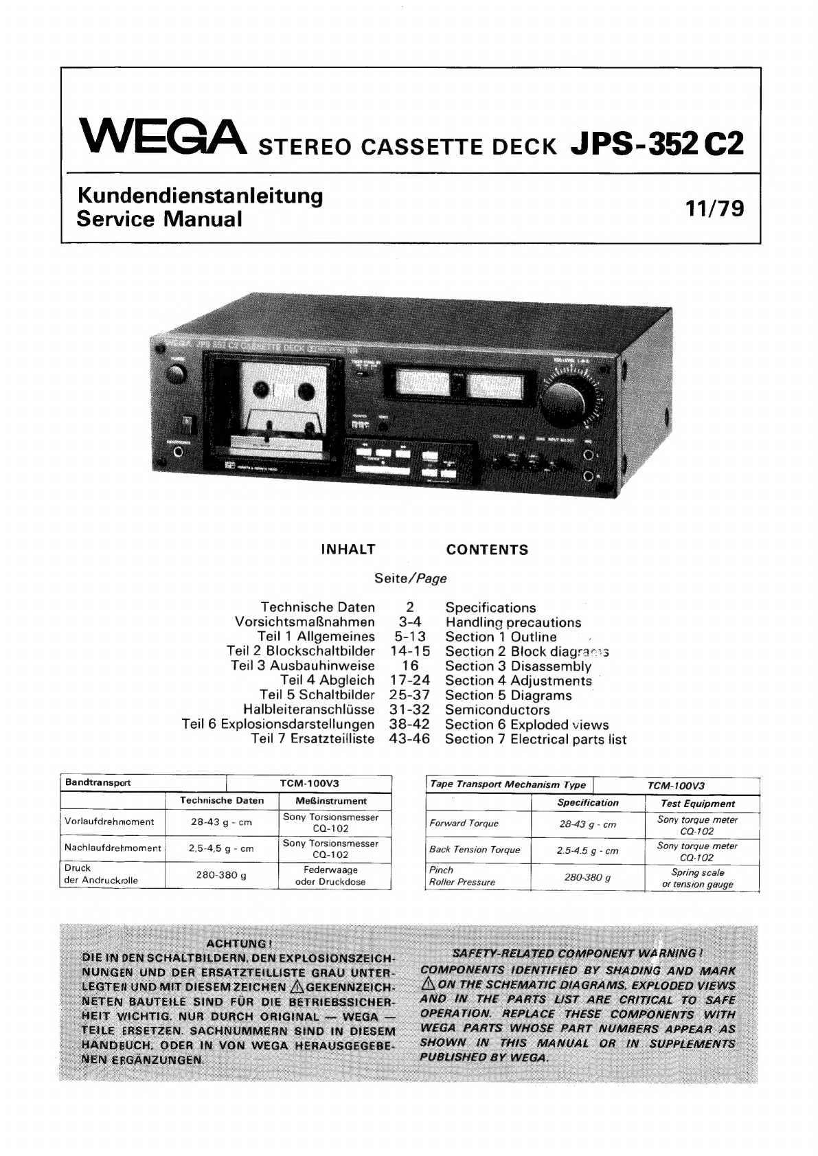
JPS-35202
SECTION
1
OUTLINE
1-1.
MECHANISM
OPERATION
This
set
switches
over
the
mode
by
the
interlocking
of
the
pause
gear
or
the
limiter
gear
with
the
driving
gear
(fixed
on
the
flywheel).
1.
Fast
Forward/Rewind
Operation
1)
Brake
Release
(See
Fig.
1)
a)
When
the
fast
forward
or
the
rewind
button
is
pushed,
the
pole
piece
of
PM1
(brake
solenoid)
is
pulled
in
direction
(A)
by
the
driving
signal
from
IC801.
b)
Pulled
by
the
pole
piece,
the
trigger
lever
(1)
moves
in
direction
(B)
and
releases
the
lock
of
the
pause
gear.
c)
As
the
pause
arm
is
pulled
by
the
spring,
it
pushes
the
cam
and
the
pause
gear
rotates
in
direction
(C).
Then
the
pause
gear
interlocks
with
the
driving
gear.
(The
driving
gear
is
fixed
on
the
flywheel
and
rotates
in
direction
(D)).
d)
The
cam
pushes
the
pause
arm
in
direction
(E),
and
the
brake
arm
pushes
the
brake
plate
up
in
direction
(G).
e)
As
the
pause
gear
moves
in
direction
(C),
the
protruded
part
of
the
pause
gear
hits
the
trigger
lever
(1)
(See
(a)
in
Fig.
2)
and
the
pause
gear
stops
rotating.
Thus
the
fast
forward
or
rewind
mode
is
maintained.
JPS-352€2
hervorspringender
Teil
.
protruded
part
Antriebsrad
Kopfmagnet
(PM2)
driving
gear
head
solenoid
(PM2})
Bremsmagnet
(PM1)
brake
solenoid
(PM1)
Pausenrad
: .
Triggerhebel
(2)
hervorspringender
Teil
;
Triggerhebel
(1)
Pause
gear
protru
is
d
ae
trigger
level
(2)
trigger
level
(1)
Begrenzerrad
limiter
gear
Anm.:
@
=
Achse
Note
:
®
=
axis
Abb.
2
Fig.
2
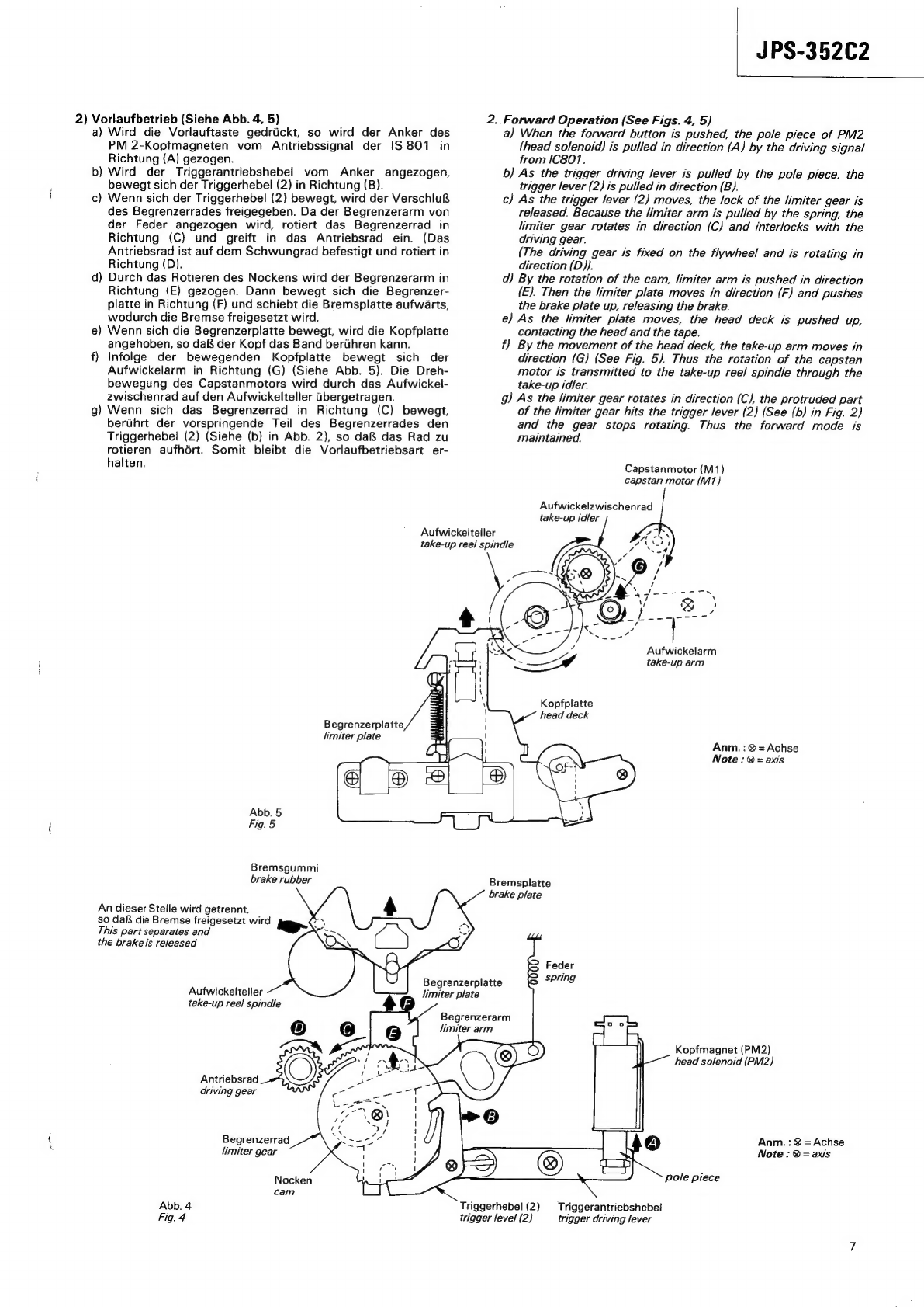
2.
Wickeltellerantrieb
(Siehe
Abb.
3)
2)
Reel
Spindle
Driving
(See
Fig.
3)
Pausenhebel
pause
arm
"p,
Anker
pole
piece
CA
a
v4
K
Bremsmagnet
(PM1)
A"
:
brake
solenoid
(PMT)
Ree
Antriebsrad
O°N
LD
driving
gear
Nocken
Pausenrad
:
cam
pause
gear
Triggerhebel
(1)
trigger
lever
(1)
Feder
spring
Abb.
1
Fig.
1
Bremshebel
brake
arm
Bremsgummi
Brake
rubber
An
dieser
Stelle
wird
getrennt,
“GBM
0
daB
die
Bremse
freikommt.
This
part
separates
and
the
brake
is
released.
Bremsplatte
brake
plate
Abwickelteller
supply
ree!
spindle
Anm.
:
@
=
Achse
Note
:
@
=
axis
a)
Wird
die
Schnellvorlauf/Riickspultaste
gedriickt,
so
rotiert
der
Wickelmotor,
vom
Signal
der
1S
801
angetrieben,
in
folgende
Richtung
:
@nachrechts
.............
in
der
Schnellvorlaufbetriebsart
@nachlinks
.........
0.0.0.0
in
der
Ruckspulbetriebsart
b)
Durch
die
vom
rotierenden
Schnellvorlauf/Rickspulzwi-
schenrad,
—
das
in
den
Wickelmotor
eingreift
-
erzeugte
Reibung
bewegt
sich
die
Schnellvoriauf/Riickspulwahiplatte
entweder
in
Richtung
(A)
(Schnellvorlaufbetrieb)
oder
Richtung
(B)
(Riickspulbetrieb).
Dann
rotiert
der
Wickelteller.
Schnellvorlaufen
fast
forward
Schnellvorlauf/Rickspulwahiplatte
fast
forward/rewind
changing
plate
Abwickelteller
—.~
supply
reel
spindle
a)
When
the
fast
forward
or
rewind
button
is
pushed,
the
reel
peas
rotates
in
the
following
direction
by
the
driving
signal
from
i
1.
@
clockwise
in
fast
forward
mode
@
counterclockwise
inrewind
mode
.
b)
By
the
friction
caused
by
the
rotation
of
the
fast
forward/re-
*
wind
idler,
which
is
interlocked
with
the
reel
motor,
the
fast
forward/rewind
changing
plate
moves
in
either
direction
(A)
{in
fast
forward
mode)
or
direction
(B)
{in
rewind
mode).
Then
the
reel
spindle
rotates.
Rucklaufen
rewind
Wickelmotor
(M2)
reel
motor
(M2)
Schnellvorlauf/Rickspulzwischenrad
fast
forward/rewind
idler
Aufwickelteller
take-up
reel
spindle
Anm.
:
@
=
Achse
Note
:
®
=
axis