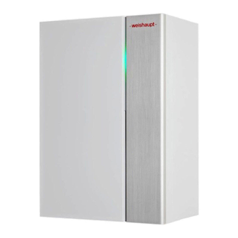
Weishaupt WWP LI 16-A R User manual

manual
Installation and operating instructions
Weishaupt
Air-to-water heat pump for indoor installation·WWP LI 16-A R 83321202 · 09/2020


Installation and operating instructions
WWP LI 16-A R
452169.66.10 · 09/2020 · Rei 183321202
Table of contents
1 Safety notes ..................................................................................................................................... 2
1.1 Symbols and markings .............................................................................................. 2
1.2 Intended use ................................................................................................................ 2
1.3 Legal regulations and directives.............................................................................. 2
1.4 Energy-efficient use of the heat pump................................................................... 3
2 Intended use of the heat pump ............................................................................................. 4
2.1 Area of application...................................................................................................... 4
2.2 Operating principle..................................................................................................... 5
2.3 Functional description for integrated thermal energy metering ....................... 5
3 Scope of supply ............................................................................................................................. 6
3.1 Basic device.................................................................................................................6
3.2 Switch box.................................................................................................................... 7
3.3 Accessories pack ....................................................................................................... 8
4 Accessories ...................................................................................................................................... 9
4.1 Air conditioning ........................................................................................................... 9
4.2 Building management system.................................................................................. 9
5 Transport..........................................................................................................................................10
6 Installation.......................................................................................................................................13
6.1 General information..................................................................................................13
6.2 Condensate pipe ......................................................................................................14
6.3 Sound..........................................................................................................................14
7 Assembly..........................................................................................................................................15
7.1 General information..................................................................................................15
7.2 Air connection ...........................................................................................................15
7.3 Connection on heating side ...................................................................................17
7.5 Electrical connection................................................................................................21
8 Commissioning.............................................................................................................................24
8.1 General information..................................................................................................24
8.2 Preparation.................................................................................................................24
8.3 Procedure...................................................................................................................24
9 Cleaning / maintenance ..........................................................................................................26
9.1 Maintenance...............................................................................................................26
9.2 Cleaning the heating system..................................................................................26
9.3 Cleaning the air system...........................................................................................27
10 Faults / troubleshooting..........................................................................................................28
11 Decommissioning / disposal................................................................................................29
12 Device information......................................................................................................................30
Appendix........................................................................................................................................................I

452169.66.10 · 09/2020 · Rei 283321202
Installation and operating instructions
WWP LI 16-A R
1 Safety notes
1 Safety notes
1.1 Symbols and markings
Particularly important information in these instructions is marked with CAUTION! or
NOTE.
ACHTUNGCAUTION
Immediate danger to life or danger of severe personal injury or significant damage to
property.
Note
Risk of damage to property or minor personal injury or important information with no
further risk of personal injury or damage to property.
1.2 Intended use
This device is only intended for use as specified by the manufacturer. Any other use
beyond that intended by the manufacturer is considered improper use. This requires
the user to abide by the relevant project planning documents. Please refrain from
tampering with or altering the device.
1.3 Legal regulations and directives
This heat pump is designed for use in a domestic environment according to Article 1,
Paragraph 2 k) of EU directive 2006/42/EC (Machinery Directive) and is thus subject
to the requirements of EU directive 2014/35/EU (Low Voltage Directive). It is thus also
intended for use by non-professionals for heating shops, offices and other similar
working environments, agricultural establishments and hotels, guest houses and other
residential buildings.
The construction and design of the heat pump complies with all relevant EU directives,
and DIN/VDE regulations (see CE declaration of conformity).
When connecting the heat pump to the power supply, the relevant VDE, EN and IEC
standards are to be adhered to. Any further connection requirements stipulated by
local utility companies must also be observed.
When connecting the heating system, all applicable regulations must also be adhered
to.
This device can be used by children aged 8 and over and by persons with limited
physical, sensory or mental aptitude or lack of experience and/or knowledge, providing
they are supervised or have been instructed in safe use of the device and understand
the associated potential dangers.
Children must not play with the device. Cleaning and user maintenance must not be
carried out by children without supervision.
ACHTUNGCAUTION
When operating or maintaining a heat pump, the legal requirements of the country
where the heat pump is operated apply. Depending on the refrigerant fill quantity, the
heat pump must be inspected for leaks at regular intervals by a certified technician, and
these inspections must be recorded.
More information can be found in the accompanying log book.

Installation and operating instructions
WWP LI 16-A R
1 Safety notes
452169.66.10 · 09/2020 · Rei 383321202
1.4 Energy-efficient use of the heat pump
With the purchase of this heat pump, you are helping to protect the environment.
A prerequisite for energy-efficient operation is the correct design of the heat source
system and heating system.
To maintain heat pump efficiency, it is particularly important to keep the temperature
difference between the heating water and heat source to a minimum. For this reason,
it is advisable to design the heat source and heating system very carefully. A
temperature difference of approx. 1 Kelvin (1 °C) increases the power
consumption by around 2.5%. When designing the heating system, it should be
borne in mind that special consumers such as domestic hot water preparation should
also be taken into consideration and dimensioned for low temperatures. Underfloor
heating systems (panel heating) are optimally suited for heat pump use on account
of the low flow temperatures (30 °C to 40 °C).
It is important to ensure that the heat exchangers are not contaminated during
operation, as this increases the temperature difference, which in turn reduces the
coefficient of performance (COP).
When set correctly, the heat pump manager is also an essential factor in the energy-
efficient use of the heat pump. Further information can be found in the heat pump
manager operating instructions.

452169.66.10 · 09/2020 · Rei 483321202
Installation and operating instructions
WWP LI 16-A R
2 Intended use of the heat pump
2.1 Area of application
The air-to-water heat pump is to be used exclusively for the heating and cooling of
heating water. It can be used in new or existing heating systems.
The heat pump is suitable for mono energy and bivalent operation in outside air
temperatures to -22 °C.
Proper defrosting of the evaporator is guaranteed by maintaining a heating water return
temperature of more than 22 °C (+2 °C/-0 °C) during continuous operation.
The heat pump is not designed for the increased heat consumption required when a
building is being dried out. For this reason, the additional heat consumption should be
met using special devices provided by the customer. If a building is to be dried out in
autumn or winter, we recommend installing an additional electric heating element
(available as an accessory).
In cooling operation, the heat pump is suitable for air temperatures ranging from +15
°C to + 40 °C. It can be used for silent and dynamic cooling. The minimum cooling
water inlet temperature is +7 °C.
Note
The device is not suitable for operation with a frequency converter.

Installation and operating instructions
WWP LI 16-A R
2 Intended use of the heat pump
452169.66.10 · 09/2020 · Rei 583321202
2.2 Operating principle
Heating
Outside air is drawn in by the fan and fed via the evaporator (heat exchanger). The
evaporator cools the air, i.e. extracts heat from it. This extracted heat is then transferred
to the working medium (refrigerant) in the evaporator.
The heat is "pumped" to a higher temperature level by increasing its pressure with the
aid of an electrically driven compressor. It is then transferred to the heating water via
the liquefier (heat exchanger).
Electrical energy is used to raise the temperature level of the heat from the
environment. Since the energy extracted from the air is transferred to the heating water,
this type of device is referred to as an air-to-water heat pump.
The air-to-water heat pump consists of the main components: evaporator, fan,
expansion valve, compressor, the liquefier and the electrical control system.
At low ambient temperatures, humidity accumulates on the evaporator in the form of
frost, reducing the transfer of heat. Uneven accumulation during this process does not
indicate a fault. The evaporator is defrosted automatically by the heat pump as
required. Under certain atmospheric conditions, steam may be emitted from the air
outlet.
Cooling
The functions of the evaporator and the liquefier are reversed in the "Cooling"
operating mode.
The heating water transfers its heat to the refrigerant via the liquefier, which is now
functioning as an evaporator. The refrigerant is brought to a higher temperature level
using the compressor. Heat is transferred to the surrounding air via the liquefier (which,
in heating operation, functions as an evaporator).
2.3 Functional description for integrated thermal energy
metering
The compressor manufacturer’s performance specifications for different pressure
levels are stored in the heat pump software. Two additional pressure sensors for
determining the current pressure level are installed in the refrigeration circuit of the
heat pump, one before and one after the compressor. The current heat output can be
calculated from the compressor data stored in the software and the current pressure
level. The integral for the heat output over the runtime gives the quantity of thermal
energy supplied by the heat pump, which is displayed separately for heating, domestic
hot water preparation and swimming pool water preparation on the heat pump
manager’s display.
The integrated thermal energy metering must not be used for heating cost billing
purposes. EN 1434 is not applicable.

452169.66.10 · 09/2020 · Rei 683321202
Installation and operating instructions
WWP LI 16-A R
3 Scope of supply
3 Scope of supply
3.1 Basic device
The heat pump contains the components listed below.
The refrigeration circuit is "hermetically sealed" and contains the fluorinated refrigerant
R410A incorporated in the Kyoto protocol. Information on the GWP value and CO2
equivalent of the refrigerant is available under “Device information”. The refrigerant is
CFC-free, non-ozone depleting and non-combustible.
1. Evaporator
2. Expansion valve
3. Fan
4. Switch box
5. Filter dryer
6. Liquefier
7. Compressor
1
2
3
4
5
6
7

Installation and operating instructions
WWP LI 16-A R
3 Scope of supply
452169.66.10 · 09/2020 · Rei 783321202
3.2 Switch box
The switch box is located in the heat pump. The switch box cover can be removed once
the lower front cover has been removed and the two screws on the side have been
unfastened.
(Mains)connecting terminals, power electronics for the compressor, refrigeration
circuit controller and heat pump manager are located in the switch box
The heat pump manager is a convenient electronic regulation and control device. It
controls and monitors the entire heating system based on the outside temperature, as
well as domestic hot water preparation and safety systems.
The external temperature sensor to be mounted on-site is included in the heat pump
scope of supply together with the necessary fixing accessories.
The enclosed operating instructions describe the function and use of the heat pump
manager.
In order to simplify service work on the refrigeration circuit, it is possible to remove the
switch box and position it next to the device. For this, the cover must be removed and
the switch box disconnected from the cooling.
1. Remove switch box cover
2. Unfasten 2x screws for cooling
3. Disconnect supply lines at the controller and
guide through grommet
4. Unfasten 2x screws for switch box
5. Push the switch box slightly to the right
and lift it out to the front
2
15
3
4

452169.66.10 · 09/2020 · Rei 883321202
Installation and operating instructions
WWP LI 16-A R
3 Scope of supply
3.3 Accessories pack
On top of the heat pump:
1 x insulating mat, duct connection
1 x small sealing ring, air intake
1 x large sealing ring, air outlet
In the condensate tray:
1 x external sensor with mounting material
Under fan:
8 x sealing plugs ø 30 - black
Outside the packaging:
Documentation

Installation and operating instructions
WWP LI 16-A R
4 Accessories
452169.66.10 · 09/2020 · Rei 983321202
4 Accessories
4.1 Air conditioning
With cooling using panel heating/cooling systems, regulation is carried out according
to the room temperature and humidity measured.
This is done by setting the desired room temperature on the heat pump manager or
room control unit. The minimum possible cooling water temperature is calculated from
the room temperature and humidity measured in the reference room. The control
response of the cooling system is influenced by the currently measured room
temperature and the set room set temperature.
4.2 Building management system
The heat pump manager can be connected to a building management system network
via supplementation of the relevant interface plug-in card. The supplementary
installation instructions of the interface card must be consulted regarding the exact
connection and parametrisation of the interface.
The following network connections can be made on the heat pump manager:
Modbus
EIB, KNX
Ethernet

452169.66.10 · 09/2020 · Rei 10 83321202
Installation and operating instructions
WWP LI 16-A R
5 Transport
5 Transport
ACHTUNGCAUTION
When transporting the heat pump, ensure that it is not tilted by more than 45° (in any
direction).
A pallet should be used to transport the heat pump to its final installation location. The
basic device can be transported with a lift truck, hand truck or by means of 3/4" pipes
fed through the holes in the baseplate or frame.
The heat pump and the transport pallet are joined by four anti-tipping devices. These
must be removed.
Before using the transport holes in the frame, it is necessary to remove the lower panel
assemblies. This is done by loosening each of the two screws at the base and then
withdrawing the panels by unhooking them from above. Rehang the panels by gently
pushing them in an upwards direction.
Be careful not to damage any components when inserting the pipes through the frame.
Any transport holes are to be covered at the installation location using the 8 black dust
caps, which are included in the device’s accessories pack.
After transportation, the transport fastening in the device is to be removed from both
sides of the base.
Opening the cover Closing the cover
3.
1.
1.
3.
2.
3.
3.
1.
1.
2.

Installation and operating instructions
WWP LI 16-A R
5 Transport
452169.66.10 · 09/2020 · Rei 11 83321202
ACHTUNGCAUTION
Before commissioning, the transport fastening must be removed.
For easier transportation into existing homes/buildings, it is possible to separate the
basic device into two parts.
Once the covering panels have been removed, please proceed as follows:
1. Drain refrigerant
2. Remove condensate hose
3. Remove the pipe insulation above the soldering points
4. Separate 4x soldering points chip-free.
5. Disconnect cable on the fan and pull through the
cable glands in the condensate tray.
6. Unfasten 4x screws in the corners in each case
7. Lift down the top part of the heat pump
8. Areas for lifting on the frame
9. Transport heat pump to the installation location
10. Join the parts
11. Re-solder the separation points again (with inert gas flushing)
12. Evacuate the refrigeration circuit
13. Add refrigerant
14. Perform leakage tightness test
15. Re-attach pipe insulation
16. Re-connect fan
17. Bores for attaching a transport aid (e.g. lifting straps etc.)
ACHTUNGCAUTION
Do not lift by the condensate tray. This cannot withstand any forces.
ACHTUNGCAUTION
Work on the refrigeration circuit and electrics may only be performed by competent
experts.
ACHTUNGCAUTION
The condensate hose must be removed before the upper part is put down.
Transportsicherung
entfernen/einschrauben
Removing/screwing in
transport fastening

452169.66.10 · 09/2020 · Rei 12 83321202
Installation and operating instructions
WWP LI 16-A R
5 Transport
2
3+4
D
6
8
7
17

Installation and operating instructions
WWP LI 16-A R
6 Installation
452169.66.10 · 09/2020 · Rei 13 83321202
6 Installation
6.1 General information
The device is designed to enable several connection options. The position of the air
outlet opening can be moved from right (factory default) to left or top by turning over
one of the two screwed on covers.
By replacing the bottom side panel assemblies, it is also possible to move the hydraulic
connection from left (factory default) to right. The different connection options are
shown in the dimension drawing (Chapter 1 on page II).
The air-to-water heat pump must be installed in a frost-free, dry room on an even,
smooth and horizontal surface. The entire base of the frame should lie directly on the
floor to ensure an adequate soundproof seal. If supporting feet are used, the heat
pump must be installed horizontally. In this case, the specified sound level can be up to
3 dB(A) higher, and additional sound insulation measures may be necessary.
If the device is installed on top of a built-under buffer tank, a surface that fully supports
the base is required. The heat pump must be installed in a way that allows maintenance
work to be carried out without hindrance. This can be ensured by maintaining a
clearance of 1 m in front of the heat pump and to the side on which the heating water
connections are located.
The side panel assemblies must not be covered by connecting pipes.
Neither frost nor temperatures higher than 35 °C must occur in the installation room at
any time of the year.
Never install the device in rooms subject to high humidity. Condensation can form on
the heat pump and air circuit if the humidity exceeds 50% and the outside temperature
is below 0 °C.
If the heat pump is installed on an upper storey, the load-bearing capacity of the ceiling
should be checked. On account of the acoustics, measures for isolating possible
vibrations should also be very carefully planned in advance as well. Installation on floors
above wooden ceilings is not recommended.
1 m
(0,11 m)
1m
0,1 m
0,11 m
(1 m)

452169.66.10 · 09/2020 · Rei 14 83321202
Installation and operating instructions
WWP LI 16-A R
6 Installation
6.2 Condensate pipe
Condensate that forms during operation must be drained off frost free. To ensure
proper drainage, the heat pump must be mounted horizontally. The condensate pipe
must have a minimum diameter of 50 mm and must be fed into a sewer in such a way
that it is safe from frost. Do not discharge the condensate directly into clarifiers or cess
pits. The aggressive vapours and a condensate pipe laid in an area which is not frost
free can destroy the evaporator.
6.3 Sound
We recommend connecting the heat pump to the heating system using a flexible
hose to prevent solid-borne noise transmission to the heating system if requirements
regarding noise are high.
Installed air ducts should be sound-isolated from the heat pump to prevent the
transmission of solid-borne sound to the ducts.
If the transport restraint screws are not removed from the compressor, acoustic
emissions from the device are significantly louder!

Installation and operating instructions
WWP LI 16-A R
7 Assembly
452169.66.10 · 09/2020 · Rei 15 83321202
7 Assembly
7.1 General information
The following connections need to be established on the heat pump:
- Supply and exhaust air
- Flow and return of the heating system
- Condensate drain
- Power supply
- Temperature sensor (e.g. external sensor)
7.2 Air connection
ACHTUNGCAUTION
Do not restrict or block the area around the intake or the air outlet area.
ACHTUNGCAUTION
Only operate the heat pump with the air ducts connected.
The glass fibre reinforced concrete air ducts offered as accessories are moisture
resistant and diffusion free (exhaust air duct 600 (600 x 600) and inlet duct 800 (769
x 769)). When using the air duct for the air outlet side (600 x 600), the "insulating mat
duct connection" (in the accessory pack) is to be adhered to the air outlet on the
desired connection side.
The sealing collar is used to seal the air ducts on the heat pump. The air ducts
themselves are not screwed directly onto the heat pump. When the system is installed
ready for operation, only the rubber seal comes into direct contact with the heat pump.
This guarantees easy assembly and disassembly of the heat pump and also ensures
that solid-borne sound is well insulated.

452169.66.10 · 09/2020 · Rei 16 83321202
Installation and operating instructions
WWP LI 16-A R
7 Assembly
If an alternative air duct is being used to that which has been supplied as an accessory,
care must be taken to ensure that it does not reduce the cross-sectional area of the air
intake and air outlet sides. The "small and large sealing rings" included in the scope of
supply can be used for sealing the heat pump connection. They also function as
vibration isolators.
The large sealing ring can be used to position the air intake opening of the heat pump
directly onto an appropriately constructed wall opening.
It must be ensured that the interior side of the wall opening is lined with thermal
insulation to prevent the wall from becoming cold and to prevent moisture from
penetrating the wall.
When very short air ducts are used on the air outlet, the exterior side of the wall
opening must be fitted with a safety guard or an air deflector grille suitable for
preventing body parts (fingers or arms, especially those of children) coming into
contact with the fan in the heat pump.
If flange-mounted air ducts are used, connecting stubs are secured on the air inlet and
air outlet sides with 4 M8 hexagon bolts in the threaded holes provided (the hexagonal
long nuts). When doing this, ensure that both air duct stubs touch only the insulation.
There should be no contact with the external sheeting.
Also ensure that the vibration and duct insulation are adequate
M8

Installation and operating instructions
WWP LI 16-A R
7 Assembly
452169.66.10 · 09/2020 · Rei 17 83321202
7.3 Connection on heating side
The heating system connections on the heat pump have a 1" internal thread. A spanner
must be used to firmly grip the transitions when connecting the heat pump.
The connection on the heating side can also be made towards the right. To do this, the
left and right bottom panel assemblies must be removed. The two connecting pipes,
including pipe supports, must be moved from the left to the right side of the device. The
panel assemblies must then be re-mounted the opposite way around.
Before connecting the heating water system to the heat pump, the heating system
must be flushed to remove any impurities, residue from sealants, etc. Any accumulation
of deposits in the liquefier may cause the heat pump to completely break down. For
systems in which the heating water flow rate can be shut off via the radiator or
thermostat valves, an overflow valve must be installed on-site in a heating bypass
downstream from the heat pump. This ensures a minimum heating water flow rate
through the heat pump and helps to avoid faults.
Once the heat pump has been connected to the heating system, it must be filled,
purged and pressure-tested.
The following points must be observed when filling the system:
Untreated filling water and make-up water must be of drinking water quality
(colourless, clear, free of deposits)
Filling water and make-up water must be pre-filtered (max. pore size 5 µm).
Scale formation in domestic hot water heating systems cannot be avoided, but in
systems with flow temperatures below 60 °C, the problem can be disregarded. With
high-temperature heat pumps and in particular with bivalent systems in the higher
performance range (heat pump + boiler combination), flow temperatures of 60 °C and
more can be achieved. The following standard values should therefore be adhered to
with regard to the filling and make-up water according to VDI 2035, sheet 1: the total
hardness values can be found in the table.
Fig. 7.1: Guideline values for filling and make-up water in accordance with VDI 2035
For systems with an above-average specific system volume of 50 l/kW, VDI 2035
recommends the use of fully demineralised water and a pH stabiliser to minimise the
risk of corrosion in the heat pump and heating system.
ACHTUNGCAUTION
With fully demineralised water, it is important to ensure that the minimum permissible
pH value of 7.5 (minimum permissible value for copper) is complied with. Failure to
comply with this value can result in the heat pump being destroyed.
Total heat out-
put in kW
Total
Alkaline earths in
mol/m³ and/or
mmol
Specific system volume
(VDI 2035) in l/kW
< 20 20 < 50 50
Total hardness in dGH
< 50 2.0 16.8 11.2
< 0.111
50 – 200 2.0 11.2 8.4
200 – 600 1.5 8.4 < 0.111
> 600 < 0.02 < 0.111
1. This value lies outside the permissible value for heat exchangers in heat pumps.

452169.66.10 · 09/2020 · Rei 18 83321202
Installation and operating instructions
WWP LI 16-A R
7 Assembly
Minimum heating water flow rate
The minimum heating water flow rate through the heat pump must be assured in all
operating states of the heating system. This can be accomplished, for example, by
installing a hydraulic switch or an overflow valve. The procedure for setting an overflow
valve is described in the chapter "Commissioning". When the minimum heating water
flow rate is undershot, the plate heat exchanger in the refrigeration circuit can freeze,
which can lead to total loss of the heat pump.
The nominal flow rate is specified depending on the max. flow temperature in the
device information and must be taken into account during planning. With design
temperatures below 30 °C in the flow, the design must be based on the max. volume
flow with 5 K spread for A7/W35.
The specified nominal flow rate (See "Device information" on page 30.) must be
assured in all operating states. An installed flow rate switch is used only for switching
off the heat pump in the event of an unusual and abrupt drop in the heating water flow
rate and not to monitor and safeguard the nominal flow rate.
Frost protection
A method of manual drainage (see illustration) should be provided for heat pumps
which are exposed to frost. The frost protection function of the heat pump manager is
active whenever the heat pump manager and the heat circulating pump are ready for
operation. The system must be drained if the heat pump is taken out of service or in the
event of a power failure. The heating circuit should be operated with a suitable frost
protection if heat pump systems are implemented in buildings where a power failure
cannot be detected (holiday home).
7.4 Temperature sensor
Depending on the heat pump type used, the following temperature sensors are already installed
or must be additionally mounted:
Outside temperature (R1)
Temperature 1st, 2nd and 3rd heating circuit (R2, R5 and R13)
Flow temperature (R9), as a frost protection sensor in the case of air-to-water heat pumps
Outlet temperature of the heat source in the case of brine-to-water and water-to-water
heat pumps
Domestic hot water temperature (R3)
Temperature of renewable thermal storage (R13)
Table of contents
Other Weishaupt Heat Pump manuals
Popular Heat Pump manuals by other brands

Multistack
Multistack AirStack VersaTemp ARA 020X Product data

Glen Dimplex
Glen Dimplex HPL 9S-TUW2 Installation and operating instruction

Bryant
Bryant 657A User's information manual

Mitsubishi Electric
Mitsubishi Electric PUHZ-W50HA installation manual

Daikin
Daikin ARQ installation manual

A.O. Smith
A.O. Smith AHPW-25 User's information manual

Kronoterm
Kronoterm WPG-07-1 HT Manual for installation, use and maintenance

Dimplex
Dimplex LA 20AS Installation and operating instructions

ECR
ECR EMI AmericaSeries S1CG Installation, operation and maintenance manual

LG
LG DMC24DB-1 owner's manual

AERMEC
AERMEC ANL 100HA Technical installation manual

Intuis
Intuis Edel AIR installation manual