WELL.D MEDICAL WELLD M5V User manual

M5V
Veterinary Ultrasound Scanner
User Manual
(Version:V1.0,July, 2021)
Shenzhen Well. D Medical Electronics Co., Ltd.
Authorized Distributor
AISON INTERNATIOANL
Stigs Center 2B,
42246, Hisings Backa,Sweden
Tel:0046-73-5543108
Email: [email protected]
www.autoclave.se

I
Preface ........................................................................................................................................................................1
Copyright............................................................................................................................................................1
Statement ............................................................................................................................................................1
Manufacturer's warranty.....................................................................................................................................1
Matters need Attention .......................................................................................................................................1
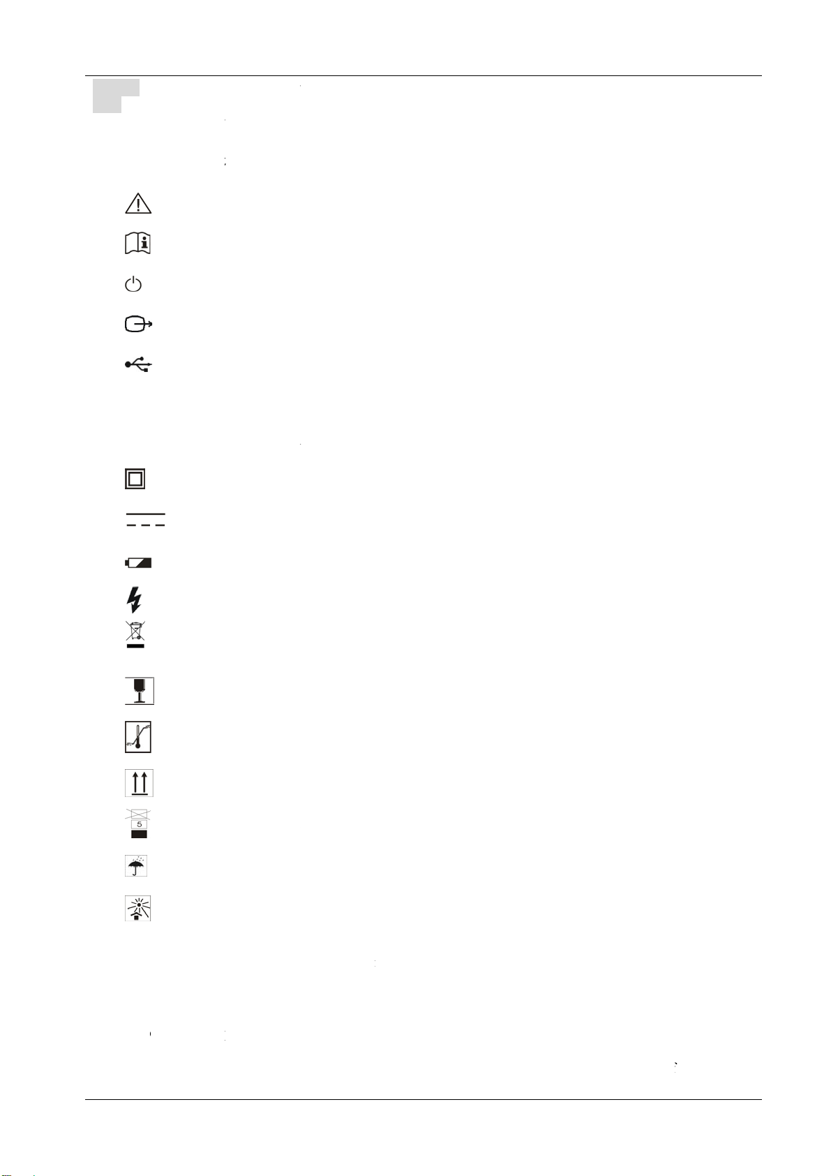
Safety labels........................................................................................................................................................2
Device safety classification ................................................................................................................................2
General tips for device operation........................................................................................................................3
General Safety Message .....................................................................................................................................3
Chapter One Summary ...............................................................................................................................................4
1.1 Brief introduction .........................................................................................................................................4
1.2 Range of application.....................................................................................................................................4
1.3 Technical specification .................................................................................................................................4
1.4 Electric principle block diagram...................................................................................................................5
1.5 Basic principle..............................................................................................................................................5
1.6 Configurations ..............................................................................................................................................5
1.7 Appearance ...................................................................................................................................................6
1.8 EMC statement: ............................................................................................................................................7
Chapter Two Installation ............................................................................................................................................8
2.1 Operating environmental requirements ........................................................................................................8
2.2 Unpacking inspection ...................................................................................................................................8
2.3 Installation and disassembly.........................................................................................................................8
2.3.1 Connection between probe and main unit..........................................................................................8
2.3.2 Installing and Removing Batteries.....................................................................................................9
2.3.3 Shoulder Strap Installation ................................................................................................................9
2.4 Charging .....................................................................................................................................................10
Chapter Three Operation Keyboard..........................................................................................................................11
3.1 Screen display.............................................................................................................................................11
3.2 Keyboard functions.....................................................................................................................................12
Chapter Four Operating Procedures .........................................................................................................................15
4.1 Boot ............................................................................................................................................................15
4.2 Image display mode....................................................................................................................................15
4.3 Image parameters adjustment .....................................................................................................................15
4.4 Function menu1 ..........................................................................................................................................15
4.5 Function menu2 ..........................................................................................................................................16
4.5.1 Cineloop ..........................................................................................................................................16
4.5.2 Image storage and Callout ...............................................................................................................17
4.5.3 Pseudo- color ...................................................................................................................................17
4.5.4 Harmonics waves and Fundamental waves .....................................................................................17
4.5.5 Screen Rotation by 90°(switching between horizontal and vertical screens) ..................................17
4.5.6 S/N...................................................................................................................................................18
4.5.7 Farm.................................................................................................................................................18
4.5.8 Time.................................................................................................................................................18
4.5.9 Clear the Image................................................................................................................................19
4.6 Distance measurement................................................................................................................................19
4.7 Volume measurement..................................................................................................................................20
4.8 Backfat measurement .................................................................................................................................20
4.9 Heart rate measurement ..............................................................................................................................21
4.10 OB calculation ..........................................................................................................................................21
4.11Image Printing(Optional)...........................................................................................................................27
4.12Power Off ..................................................................................................................................................27
Chapter Five Transportation and Storage .................................................................................................................28
5.1 Environment requirements on transportation and storage ..........................................................................28
5.2 Transportation.............................................................................................................................................28
5.3 Storage........................................................................................................................................................28
Chapter Six Check and Maintenance........................................................................................................................29
6.1 Service life..................................................................................................................................................29
6.2 Check..........................................................................................................................................................29
6.3 Main unit maintenance ...............................................................................................................................29

II
6.4 Probe maintenance......................................................................................................................................29
6.5 Cleaning of Principal Machine ...................................................................................................................30
6.6 Correct usage of probe................................................................................................................................31
6.7 Battery information ....................................................................................................................................31
6.8 Instrument test and calibration ...................................................................................................................32
Chapter Seven Trouble Shooting..............................................................................................................................33
7.1 Simple Trouble shooting.............................................................................................................................33

III
Important warning information
1. Be sure to read the Warnings, Notes and Cautions contained in this manual. This manual contains
warnings, notes and cautions regarding the foreseeable potential hazards, and vigilance shall be kept at
all times. We shall not be liable for any damage, injury or loss caused by negligence or disregard of the
precautions specified in the manual, so please ensure that you do not lose this manual.
2. It is strictly forbidden to disassemble any hardware and software of this system, and the Company shall
not be held responsible for the consequences caused by the repairs or re-installation of the equipment
by the non-designated personnel of the Company.
3. Under unnecessary conditions, we do not recommend use of UPS power supply; if you need to configure
the UPS power supply, please buy the products of qualified manufacturers or contact the Company;
when it is not used, switch off the host of B-ultrasound instrument and the UPS, and the Company is
not responsible for any damage to this system due to UPS power supply failure (short circuit, fire, etc.).
4. Other equipment connected to the system (such as regulated power supply) must comply with the
relevant electrical safety requirements, and the Company is not responsible for damage to the system
and customer loss caused by failure of other equipment.
5. The battery can be charged and discharged cyclically 300-500 times, and when the usable time of
battery is found to be shortened significantly, please replace the new battery in time to avoid failure.
6. Charging time of the system: about 5 hours, discharging time: about 3.5 hours. The battery can be used
for about 3.5 hours when it is normal in the early stage, with the increase of charging and discharging
times in the later stage, the battery capacity will gradually decrease, and the battery service time will
also decrease.
7. Please be sure to turn off the power when the equipment is not in use, and unplug the power cord and
the power terminal board if necessary. The equipment (power connection panel) should be kept away
from the roof with water leakage, including other water sources. Such conditions may cause short
circuit of power supply, fire or even burn down the equipment. The company shall not be responsible
for the above consequences.
8. Before connecting or disconnecting the probe, you must first confirm that the device is off. Otherwise,
the company will not be responsible for the above consequences caused by the damage.


1
Preface
Copyright
This publication, including pictures and illustrations, is property of Shenzhen Well. D Medical Electronics Co.,
Ltd. and under protection of international copyright law.
Statement
Information in this document are not annotated to change. The manufacture shall not state nor observe any
warranty basing on this point, and definitely give up any implied warranty basing on any special purpose of
selling or making benefit.
Without previous written permission from the producer, this document must not be photocopied, reproduced or
translated into other languages.
We preserve the right of revision on this document without still further notice.
Some pictures in this manual, which are schematic diagrams for indication only, may disaccord with the real
object, and then the real object should be regarded as the final.
are trade marks of Shenzhen Well. D Medical Electronics Co., Ltd. Any abuse of these trade
marks without permission will be sued to assume legal responsibility according to laws.
Manufacturer's warranty
Shenzhen Well. D Medical Electronics Co., Ltd. assumes the responsibility for device security, reliability and
performance only under the preconditions that the disassembly, assembly and maintenance of the device are all
performed by its assigned professional and the device is used strictly in compliance with the operation manual.
Shenzhen Well. D Medical Electronics Co., Ltd. ensures a guarantee period within a year and a half since the
delivery day and promises there is no problem with the new device in material and technology. Within the
guarantee period, Shenzhen Well. D Medical Electronics Co., Ltd. will maintain the device and replace the parts
of non-man-made damages free of charge. But will not repair or replace the device surface if it is damaged.
This guarantee is only available for failures occurred when the device is operated in compliance with the operation
manual. And the guaranteed device can only be used in the prescribed range given in manual.
This guarantee excludes losses or damages caused by external reasons such as thunder struck, earthquake, theft,
unsuitable use or abuse and refitting the device.
Shenzhen Well. D Medical Electronics Co., Ltd. shall not be responsible for damages caused by other devices or
arbitrary connection to other devices.
Shenzhen Well. D Medical Electronics Co., Ltd. shall not be responsible for losses, damages or injuries caused by
delayed service request.
When there is problem with the products, please contact Shenzhen Well. D Medical Electronics Co., Ltd. and
explain the device model, serial number, date of purchase and the problem.
Matters need Attention
To ensure operational safety and long-term stable equipment performance, please read this operation manual
closely and understand the device functions, operation and maintenance at all points before operating the device,
especially contents of "Warning", "Caution" and "Note".
Disoperation or inobservance of the instructions given by manufacturer or its agents may result in device damage
or personal injury.
The following convention works through this manual to lay special emphasis on some information.
"Warning": Stands for neglect of it will cause severe personal injury, death or realized property loss.

"Caution":
"Note": to
b
ut with n
o
Safet
y
l
Device la
b
IPX
7
IPX
5
Packing a
n
Device
s
●Accordi
n
with ox
y
M5V ca
n
●Classify
M5V is
c
●Classify
The hos
t
Stands for n
e
remind user
o
o
risk. Any
w
abels
b
els explana
t
Attent
i
Strictl
y
Switc
h
Signal
USB p
7
Protec
t
5
Anti-s
p
Class
Ⅱ
DC i
n
Charg
e
High
v
Elect
r
n
d transpor
t
Handl
e
Tempe
Upwa
r
Limite
Protec
t
Protec
t
s
afet
y
cla
n
g to the deg
y
gen or nitro
u
n
not be use
d
as per work
c
ontinuous o
p
as per har
m
f
t
machine of
e
glect of it
w
o
f installatio
n
w
arning again
s
t
ion:
i
on!consult
y
follow inst
r
h
on and off i
n
output
ort
t
ed against t
h
p
lash equip
m
device
Ⅱ
n
put 13.8V,3.
e
lamp
v
oltage risk
r
onics elect
r
t
ation labels
e
with care
rature limit
r
ds
d layers of s
t
t
against wet
n
t
against hea
t
ssificatio
n
ree of safety
u
s oxide:
d
in situation
system:
p
eration dev
i
f
ul liquid lea
k
M5V is IPX
5
w
ill cause slig
h
n
, operation
o
s
t dangers sh
a
accompanyi
n
r
uctions
n
dicato
r
ligh
t
h
e effects of i
m
m
ent
6A
r
ical equip
m
explanatio
n
t
owage
n
ess
t
n
of applicatio
n
of mixture o
f
i
ce.
k
age:
5
(anti-splas
h
2
h
t personal i
n
o
r maintenan
c
a
ll not be co
n
n
g document
s
t
m
mersion
m
ent separa
t
n
:
n
in the pres
e
f
inflammabl
e
h
equipment);
n
jury or prop
e
c
e informati
o
n
tained in N
O
s
t
e collectio
n
e
nce of a fla
m
e
anaesthesia
the probe is
e
rty damage.
o
n. These inf
o
O
TE.
n
m
mable anae
s
gas and air
o
a device of r
e
o
rmation is v
s
thetic mixtu
r
o
r nitrous oxi
e
sistance to
f
ery significa
n
r
e with ai
r
or
de.
f
looding.
n
t

3
●Classify according to shockproof type:
M5V is Group device powered by external adapter.Ⅱ
●Classify according to shockproof level:
M5V is Type B Applied part
General tips for device operation
In operation
1.Heat radiation lump are strictly prohibited to be covered.
2.After closedown, do not switch on the device within 1 minute.
3.On scanning, if any abnormal case is found, stop scanning immediately and shut down the device.
After operation
1. Power off the device.
2. Pull out the plug from power supply socket instead of pulling the cable.
3. Clean off the couplant on the probe with soft medical sterilized cotton ball.
General Safety Message
Safety of the operator and patients and reliability of the device are taken into consideration during designing and
producing, the following safety precaution must be implemented:
1. The device shall be operated by qualified operating staff or under their instructions.
2. Do not open the device and change the parameters without permission. If necessary, please turn to for
Shenzhen Well.D Medical Electronics Co., Ltd. or its authorized agent for service.
3. The device has already been regulated into its optimal performance. Do not adjust any preset control or switch
unless operate as per instructions in the manual.
4. If there is device failure, please shut down the device at once and contact for Shenzhen Well.D Medical
Electronics Co., Ltd. or their authorized agent.
5. If it is needed to connect the device with other company’s' electronic or mechanical devices,please contact
Shenzhen Well. D Medical Electronics Co,. Ltd. before connection.
6. Device operation, storage and transportation environment
Environmental requirements on normal operation:
a) Environment temperature range:+5℃~+40℃
b) Relative humidity range: ≤80%
c) Atmosphere pressure range: 700hPa~1060hPa
Environment requirements on device storage and transportation:
a) Environment temperature range: -20℃~+55℃
b) Relative humidity range: <80%(20℃)
7. Do not hit the fragile TFT-LCD display. If it cracks, deal carefully with it in case the liquid crystal gets into
eyes or mouths.
8. Must not hit the inner rechargeable lithium battery nor throw it into fire in case it trigger an explosion;Do not
short circuit the battery output electrodes in case the battery be damaged; and please use the original binding
charger to charge the battery. More over, because used battery will cause environment pollution, please handle
the battery correctly for recovery processing.
9. Must not disassemble the power supply adapter. If failures happen, it should be handled by the professional; the
charging output can only be used for charging the battery of the device, any improper use on other battery may
cause explosion, fire and other unexpected hazards.
10. Must not short circuit the output of the adapter,a long term short circuit shall result in adapter damage.
11. Please use standard power cord as the input line of the network power supply for the adapter to reduce risk.
12. Shenzhen Well. D Medical Electronics Co., Ltd. shall not take any responsibility for any risk resulted from
propelled / unauthorized re-fitment by the users.
13.To disconnect the device from the power supply network by unplug the adapter from the power supply
network.

4
Chapter One Summary
1.1 Brief introduction
This equipment is high resolution linear/convex ultrasound scanning diagnostic equipment. It adopts
micro-computer control and digital scan converter (DSC), digital beam-forming (DBF), real time dynamic
aperture (RDA), real time dynamic receiving apodization, real time Dynamic receiving focusing (DRF), Digital
frequency Scan (DFS), frame correlation technologies to endue its image with clarity, stability and high
resolution.
◆Five display modes: B, B+B, B+M, M; Can realize image real time display, frozen, save,svload,cineloop;
farm,vpid,time,pseudo color;backfat measurement,distance measurement ,volume measurement ,obstetric
measurement ,heart rate measurement ; Image gray scale 256 levels.
◆Combined power supply mode of AC adapter and built-in Li-ion chargeable battery, the specialized brownout
mode enables more lasting battery operation.
1.2 Range of application
Suitable for diagnosis on horses, cows, sheep, pigs, cats and dogs and other animals.
1.3 Technical specification
Probe
L1-5/7.5MHz HF
linear probe
LV2-4 6.5MHz
Rectal probe
C1-11/50R/3.5MHz
convex probe
C4-9/20R/5.0MHz
Convex rectal
probe
35LV150CP/3.5
MHz
Backfat probe
Detect Depth(mm) ≥50 ≥140 ≥140 ≥160
Resolution
(mm)
Lateral ≤2(Depth≤40)
≤3 (Depth≤80)
≤4 (80<Depth≤
130)
≤3 (Depth≤80)
≤4 (80<Depth≤
130)
≤3 (Depth≤80)
≤4 (80<Depth
≤130)
Axial ≤1 (Depth≤50) ≤2(Depth≤80) ≤2 (Depth≤80)
≤2 (Depth≤80)
≤3 (80<Depth
≤130)
Blind zone(mm) ≤3 ≤7 ≤7 ≤5
Geometric
position
precision
Horizontal ≤10 ≤20 ≤20 ≤15
Vertical ≤5 ≤10 ≤10 ≤10
Monitor size 7.0 inch(16:9)
Display mode B, B+B, B+M, M
Image gray scale 256 Scale
Image storage 64 Frame
Cine loop ≥400 frame
Image Process Pseudo Color
Frame correlation Adjustable

5
Measurement Distance,Volume,Heart rate
Notation FARM,Number,TIME
Output USB2.0, Video(if the backfat probe is selected, there will be no image printing
function)
Battery Continuous work ≥1Hour
Size L (200mm)*W(160mm)*H(35mm)
Net weight 950g
1.4 Electric principle block diagram
Picture 1-1 Electric principal block diagram
1.5 Basic principle
Veterinary ultrasound scannerworks in this following procedure: different tissues of animal body possess different
densities and speeds of transmission of ultrasound, i.e. different acoustic impedance (product of media density and
sound speed).when piezo-chip (transductor) gets certainly regulated electric impulse, it will produce ultrasound
with certain frequency. when this ultrasound (sound energy) is injected into animal body, different organ surfaces
will produce reflection echo, the different size reflection is received by the transductor which emitted ultrasound
and is changed into electric impulse, when this electric impulse is amplified, demodulated, digital scanned, shifted
and some other handling, video standard signal is produced and organ cross-sectional images are displayed on the
monitor.
1.6 Configurations
◆Mainframe(containing a piece of Li-ion battery)
◆Optional probes: LV2-4 Rectal probe,
C1-11/3.5MHz Convex probe,
C4-9/Convex rectal probe,
L1-5/7.5MHz HF linear probe,
35LV150CP Backfat probe,
◆Manual/ technical instructions
◆Main charger (AC-adapter)
◆Optional pieces: Printer
Warning:
Please select spare parts models prescribed above. The manufacturer will
not assume the risks such as safety problem, non-expected drop of EMC
performance that cause by arbitrary adoption of spare parts out of
prescription.

6
1.7 Appearance
Picture 1-2. front sketch map
Picture 1-3. Schematic diagram of right interface
Shoulder strap
fixed shafts
Handle
Keyboard
Shoulder strap
fixed shafts
Shoulder strap
fixed shafts
On/Off and charging
indicator light
Shoulder strap
fixed shafts
Battery position
USB interface
Video output (optional video
printer or video glasses)
Probe interface protection
cover
DC input
Probe interface
Interface protection
cover

7
Picture 1-4 back side sketch map
1.8 EMC statement:
M5V shan't affect the basic performance of radio service and other equipments, and can work well in the expected
and declared electromagnetic environments.
Warning:
Working in intense electromagnetic environment, its images may be
interfered and the diagnoses may be affected. By this time, stop operating
to avoid misdiagnosis. Reuse after the electromagnetic interference is
removed.
Warning:
Working when the device is overlapped with other devices or close to
others might cause unexpected EMC problems; If they have to be put
together, please check every one to ensure no one is affected by unexpected
EM coupling.
Warning:
Replacement of parts that not according with specs or connection to other
devices might cause unexpected EMC problems. The possibility of
unexpected EM coupling effect should be testifies carefully.
nameplate
Cooling panel

8
Chapter Two Installation
2.1 Operating environmental requirements
1. Environment temperature range:+5℃~+40℃
2. Relative humidity range:≤80%
3. Atmosphere pressure range:700hPa~1060hPa
When using, avoid strenuous vibration, keep it away from devices with high field, intense magnetic field or high
voltage; avoid strong sunlight blazing down on the display; keep the device well-ventilated, moisture proof and
dustproof.
2.2 Unpacking inspection
After unpacking, check the device according to "Packing List" and install it according to requirements and
methods described in "Installation" after affirm that there is no shipping damage.
Warning:
If there is breakage at unpacking check, it is banned to use the device to ensure
security.
2.3 Installation and disassembly
2.3.1 Connection between probe and main unit
The probe socket is located on the lower right side of the equipment. There is only one plug jack which is also
compatible for those optional probes (as shown in the figure).
ketch
Warning:
Avoid by all means unplugging or plugging the probe connector at state of log on
in case the probe and main unit be damaged.
Once the probe is connected with the main unit, do not unplug nor plug it at
discretion in case poor contact happen.
①
Open the protective cover of the socket
②
Make sure that the sign of “▲▲” faces upwards
Insert the probe in the direction of the arrow
and take out the probe in the opposite
direction of the arrow
Attention:
When the probe is not connected, be sure to cover
the socket protective cover.
The probe must be inserted or removed in the
shutdown state.

9
Warning:
The probe should be protected from felling off or crashing and the manufacturer
assumes no responsibility for this kind of hazard.
Warning:
Please handle the device carefully.
2.3.2 Installing and Removing Batteries
2.3.3 Shoulder Strap Installation
Shoulder Strap Installation: As shown in the Figure below, connect the lock buckles of the two shoulder straps
to the four fixed shafts of the instrument.
Warning:
Must not touch the contact pin in the probe connector.
If the shoulder strap buckles are
connected to fixed shafts, the
instrument can be looped around
the waist
If the shoulder strap buckles are
connected with fixed shafts, the
instrument can be suspended on the
neck
①
Battery label
②Fasten the battery with 2 nuts
③
Insert the waterproof rubber plug
Interface protective
cover
To take out the battery, take out the waterproof rubbe
r
p
lugs in turn, remove 2 nuts, and use 2 thumbs to pic
k
out the battery along the left and right sides.

10
2.4 Charging
Open the interface protective cover, and insert the DC plug o
f
adapter into the charging port of host machine. After the
charging is complete, there is need to unplug the plug, an
d
close the interface protective cover.
Attention:
Charging time: A
b
out 5 hours. Battery service time in the early stage
is about 3.5 hours. With the increase of charging and discharging times
in the later stage, the battery capacity may gradually decrease and the
battery service time may also decrease.
Charging indicator:
Green on: Charging
Off: The battery is fully charged
Flashing: No battery installed

3.1 Scre
e
Probe sc
a
are
a
Ci
n
Gra
y
scal
e
C
h
e
n displa
y
a
nning
a
Far
m
n
eloop
e
h
apter
Figure 3-1
.
m
name
Thre
e
.
Screen dis
p
Number
11
e
Ope
r
p
lay image(
H
r
ation
H
orizontal a
n
System d
a
Ke
y
b
n
d Vertical)
a
te and clock
oard
Pr
o
Pr
o
Batte
r
Brightne
s
Tot
a
Freeze ta
Frame
o
be frequency
o
be type
Display dep
t
r
y indicator
s
s and contrast
a
l gain
g
correlation
t
h

12
3.2 Keyboard functions
The keyboard of the whole machine is shown in the figure.
Figure 3-2. Operation panel diagram
Vertical control & operation with left hand
In the state of horizontal control & operation 1, press →
key to enter
In the state of vertical control & operation with right hand,
continuously press 0/ key twice to enter
Vertical control & operation with right hand
In the state of horizontal control & operation 2, press →
key in turn to enter.
In the state of vertical control & operation with left hand,
press 9/ →0/ key in turn to enter.
Horizontal Operation & Control 2
In the state of vertical control & operation with right hand, press
the →key in turn to enter
Horizontal Operation & Control 1
In the state of vertical control & operation with left hand, press
the →key in turn to enter

13
Power on/off key
Press this key for 2 seconds to start or close the instrument.
Image freeze or Function menu key
Image freeze: Press this key to switch freeze and real-time status.
Function menu: Press this key to display function menu.
There are two keys on the panel. When operating horizontally, the left-side key is used to
freeze/unfreeze, and the right-side key is used to display the Function Menu1. When operating & controlling
with left or right hand, the upper key is used to freeze or unfreeze, and the lower key is used to display
the Function Menu 1
Images storage Key.
Press this key to save the image to this instrument.
Obstetric table menu key/Backfat measuring line
Press this key under real-time scanning state to active the backfat measuring line;Press this key under freeze
state to enter the obstetric table.
Measurement key
Pressing this key to enter the routine measurment.
Conversion key
The key is used to measure the cursor conversions.
Direction key
Used to adjust display depth,activeate/adjust screen parameters,move coursor,turn page,etc.
B mode selection key
Press this key to enter B mode.
B B mode selection key
Press this key to enter B+B mode.
BM/ Mmode selection key
Press this key tcontinuously to enter B+M or M mode.
Clear screen key
Press this key to clear all markings from the screen.

14
Functiopn menu 2
Press this key to display the function menu2.Press the preceding Number Key to enter the corresponding
function. To exit, there is need to press this key or Direction Key.
0~9 Number key
When used as a function key, it is used to select a submenu in the function menu operation.
When used as a character key, it is used to input characters and numbers in the input options of farm,S/N,and
time in the comment menu.

15
Chapter Four Operating Procedures
4.1 Boot
Press the key for two seconds, the power indicator on the panel is on, and the startup interface appears.
At this time, any key is pressed to enter the scanning work state.
Tip:The LCD display effect is related to the viewing angle, and the operator should adjust the viewing
angle appropriately.
Note
The ventilate panel on the back of the instrument must not be covered,
otherwise the instrument may be damaged due to overheating.
4.2 Image display mode
B mode: Press the key to enter single B mode (the default is B mode after boot).
BB Mode: In B mode, press to enter B+B mode. The screen displays two B-type images. One of them
is a “frozen” image and the other is a “real-time”image . Pressing continuously can switch the “frozen” and
“real-time”states of the left and right images .
BM/M Mode: In B mode, press key to enter B+M mode. A real-time B image and M image will be
displayed on the screen. In BM mode, press to switch to M mode.
4.3 Image parameters adjustment
In the real-time scanning state, when the screen parameters are not activated, there is need to continuously
press the direction key and to adjust the depth. And continuously press the direction key and to
activate the screen parameters, including gain, frequency, frame correlation, brightness and contrast. When
parameters are activated, there is need to continuously press and to adjust the values.
4.4 Function menu1
When operating horizontally, there is need to press the key on the right side to display the Function
Menu 1.
V1.10 : Software version number.
V1.10
0.LEFT-RIGHT
1.UP-DOWN
2.DEFAUL
TSET
Table of contents
Popular Scanner manuals by other brands

Leuze electronic
Leuze electronic CU405-2M12 Supplement to original operating instructions

Epson
Epson DS-6500 WorkForce DS-6500 Product specifications

Epson
Epson 3170 - Perfection Photo user guide

Toshiba
Toshiba JOURNEE scan PA3712D-1ETC Specifications

Velleman
Velleman VIS2 user manual

Chell
Chell MicroDAQ3 Installation and operating manual