Weller WHP 1000 User manual

WHP 1000
Betriebsanleitung - Mode d’emploi - Gebruiksaanwijzing - Istruzioni per l’uso - Operating
Instructions - Instruktionsbok - Manual de uso - Betjeningsvejledning - Manual do utilizador -
Käyttöohjeet - √‰ËÁ›Â˜ §ÂÈÙÔ˘ÚÁ›·˜ - Kullan∂m k∂lavuzu -
Návod k pouÏití - Instrukcja obs∏ugi -
Üzemeltetési utasítás - Návod na pouÏívanie - Navodila za uporabo - Kasutusjuhend -
Naudojimo instrukcija - Lieto‰anas instrukcija - Ръководство за работа -
Manual de exploatare - Naputak za rukovanje
www. .com information@itm.com1.800.561.8187

Inhaltsverzeichnis Seite
1. Achtung! 1
2. Beschreibung Technische Daten 1
3. Inbetriebnahme 1
4. Betrieb mit externem Senor 2
5. Fehleranzeige im Display 2
6. Power On Routinen 2
7. Zubehör 8. Lieferumfang 2
Table des matières Page
1. Attention! 3
2. Description Caractéristiques techniques 3
3. Mise en service 3
4. Fonctionnement avec un capteur externe 4
5. Affichages d’erreurs sur l’écran 4
6. Autres routines Power On 4
7. Accessoires 8. Descriptif du contenu 4
Inhoudsopgave Pagina
1. Attenie! 5
2. Omschrijving Technische gegevens 5
3. Inbedrijfname 5
4. Gebruik met externe sensor 6
5. Foutindicaties op het display 6
6. Andere „Power On“ routines 6
7. Toebehoren 8. Omvang van de levering 6
Indice Pagina
1. Attenzione! 7
2. Descrizione Dati tecnici 7
3. Messa in funzione 7
4. Funzionamento con sensore esterno 8
5. Indicazione di errore nel display 8
6. Altre routine „Power On“ 8
7. Accessori 8. Estensione della fornitura 8
Table of contents Page
1. Attention! 9
2. Description Technical data 9
3. Placing in operation 9
4. Operation with external Sensor 10
5. Error indications on the display 10
6. Other power- on routines 10
7. Accessories 8. Items supplied 10
Innehållsförteckning Sida
1. Observera! 11
2. Beskrivning Tekniska data 11
3. Driftsättning 11
4. Drift med extern sensor 12
5. Felindikering på displayen 12
6. Andra „Power On“-rutiner 12
7. Tillbehör 8. Leveransomfattning 12
Índice Página
1. Atención! 13
2. Descripción Datos técnicos 13
3. Puesta en servicio 13
4. Servicio con sensor externo 13
5.Indicación de fallos en la pantalla 14
6. Otras rutinas „Power On“ 14
7. Accesorios 8. Volumen de suministro 14
Indholdsfortegnelse Side
1. Bemærk! 15
2. Beskrivelse Tekniske data 15
3. Ibrugtagning 15
4. Drift med ekstern sensor 16
5. Fejlvisning i displayet 16
6. Yderligere „Power On“-rutiner 16
7. Tilbehør 8. Leveringsomfang 16
Índice Página
1. Atenção! 17
2. Descrição Dados técnicos 17
3. Colocação em funcionamento 17
4. Funcionamento com sensor externo 17
5. Indicação de falha no visor 18
6. Outras rotinas „Power On“ 18
7. Acessórios 8. Fornecimento 18
Sisällysluettelo Sivu
1. Huomio! 19
2. Laitekuvaus Tekniset tiedot 19
3.Käyttöönotto 19
4 Käyttö ulkopuolisella sensorilla 20
5. Virheilmoitukset näytössä 20
6. Muut Power on -rutiinit 20
7. Lisävarusteet 8. Toimitussisältö 20
¶›Ó·Î·˜ ÂÚȯÔÌ¤ÓˆÓ ™ÂÏ›‰·
1.
Προσοχή!
21
2.
Περιγραφή Τεχνικά στοιχεία
21
3. Λειτουργία 21
4. Λειτουργία με εξωτερικό αισθητήρα 22
5. Ενδείξεις σφάλματος στην οθόνη 22
6. Περαιτέρω ρουτίνες "Power On" 22
7. Εξαρτήματα 8. Υλικά παράδοσης 22
Íçindekiler Sayfa
1. Dikkat! 23
2. Aç∂klama Teknik bilgiler 23
3. Devreye alma 23
4. Harici sezici ile iμletim 24
5. Ekrandaki hata gösterimleri 24
6. Diğer Power On rutinleri 24
7. Aksesuar 8. Teslimat kapsam∂ 24
www. .com information@itm.com1.800.561.8187

1. LED remote (ekstern styring RS232)
2. Indikator for ekstern sensorstyring
3. Display (3-cifret 7-segment display)
4. "UP"-taste
5. Netafbryder
6. "DOWN"-taste
7. Optisk indstillingskontrol
8. Specialtaste til specialfunktioner
9. Ekstern sensor
10. RS232-interface (ekstern styring)
11. Nettilslutning
1. LED remoto (activación externa RS232)
2. Indicación de regulación de sensor externa
3. Pantalla (indicación de siete segmentos de
tres dígitos)
4. Tecla "UP"
5. Interruptor de red
6. Tecla "DOWN"
7. Control óptico de regulación
8. Tecla especial para funciones especiales
9. Sensor externo
10. Interfaz RS232 (activación externa)
11. Conexión de red
1. LED Remote (extern aktivering RS232)
2. Indikering av extern sensorstyrning
3. Display (3-siffrig 7-segmentindikering)
4. “UP”-knapp
5. Huvudströmbrytare
6. “DOWN”-knapp
7 Optisk reglerkontroll
8. Knapp för specialfunktioner
9. Extern sensor
10. RS232-gränssnitt (extern aktivering)
11. Nätanslutning
1. LED Remote (pilotage externe RS232)
2. Affichage régulation capteur externe
3. Ecran (afficheur 7 segments 3 caractères)
4. Touche “UP”
5. Interrupteur secteur
6. Touche “DOWN”
7. Voyant de contrôle température
8. Touche spéciale pour fonctions spéciales
9. Capteur externe
10. Interface RS232 (pilotage externe)
11. Prise secteur
1. LED Remote (ulkoinen ohjaus RS232)
2. Ulkopuolisen sensorisäädön näyttö
3. Näyttö (3-merkkinen 7-segmenttinäyttö)
4. "UP"-painike
5. Virtakatkaisin
6. "DOWN"-painike
7. Optinen säätövalvonta
8. Erikoispainike erikoistoiminnoille
9. Ulkopuolinen sensori
10. RS232-liitäntä (ulkoinen ohjaus)
11. Verkkoliitäntä
1. LED Remote (externe Ansteuerung RS232)
2. Anzeige externe Sensorregelung
3. Display (3-stellige 7-Segmentanzeige)
4. “UP” Taste
5. Netzschalter
6. “DOWN” Taste
7. Optische Regelkontrolle
8. Spezialtaste für Sonderfunktionen
9. Externer Sensor
10. RS232 Schnittstelle (externe Ansteuerung)
11. Netzanschluss
1. LED Remote (externe aansturing RS232)
2. Indicatie externe sensorregeling
3. Display (3-cijferig 7-segmentdisplay)
4. "UP"-toets
5. Netspanningschakelaar
6. "DOWN"-toets
7. Optische regelcontrole
8. Speciale toets voor speciale functies
9. Externe sensor
10. RS232-interface (externe aansturing)
11. Netaansluiting
1. Remote LED (external control via RS232)
2. Indication, external sensor regulation
3. Display (3-digit 7-segment display)
4. “UP” button
5. Mains switch
6. “DOWN” button
7. Optical indication of the state of
regulation
8. Key for special function
9. External sensor
10. RS232 interface (external control)
11. Mains connection
1. LED Remote (azionamento esterno RS232)
2. Visualizzazione regolazione sensori esterna
3. Display (indicatore a 3 cifre 7 segmenti)
4. Tasto "UP"
5. Interruttore di alimentazione
6. Tasto "DOWN"
7. Controllo di regolazione ottico
8. Tasto speciale per Funzioni speciali
9. Sensore esterno
10. Interfaccia RS232 (azionamento esterno)
11. Presa di alimentazione
1. Φωτοδίοδος (LED) REMOTE
(εξωτερικός έλεγχος RS232)
2. Ένδειξη εξωτερικής ρύθμισης αισθητήρα
3. Οθόνη (τριψήφια ένδειξη 7 τομέων)
4. Πλήκτρο "UP" (επάνω)
5. Γενικός διακόπτης
6. Πλήκτρο "DOWN" (κάτω)
7. Οπτικός έλεγχος ρύθμισης
8. Ειδικό πλήκτρο για ειδικές λειτουργίες
9. Εξωτερικός αισθητήρας
10. RS232 θύρα διεπαφής
(εξωτερικός έλεγχος)
11. Σύνδεση στο δίκτυο του ρεύματος
1. LED Remote (activação externa RS232)
2. Indicação de regulação externa do sensor
3. Visor (indicação de 3 dígitos,
7 segmentos)
4. Tecla "UP"
5. Interruptor principal
6. Tecla "DOWN"
7. Controlo de regulação óptico
8. Tecla específica para funções especiais
9. Sensor externo
10. Interface RS232 (activação externa)
11. Ligação de rede
www. .com information@itm.com1.800.561.8187

Quick Reference WHP 1000
UP button increase value
DOWN button decrease value
Adjust Offset
Manual heating shut down (Off)
Automatic heating shut down (Auto Off)
or (minutes)
Key function via “Power-On Routine”
Standby function ON / OFF
(- 1 -) ON
oder
(- 0 -) OFF
Change over °C / °F °C or °F
Resetting to the factory setting (FSE)
OFF
+
+
+
FSE
I
OFF
3 sec
www. .com information@itm.com1.800.561.8187

We thank for the confidence you have shown by purchasing
the Weller Heating Plate WHP 1000. During manufacture the
strictest quality requirements are applied; these assure the
correct function of the device and make it possible to obtain
optimal soldering results.
1. Attention!
Prior to placing the device in operation, please carefully read
these operating instructions and the safety instructions
enclosed. If the safety instructions are not observed, there is
a risk of injury.
The manufacturer accepts no liability for usage other than
that described in the operating instructions or for unauthori-
sed modifications
The WELLER heating plate WHP 1000 complies with the EU
declaration of conformity as per the essential safety
requirements in the directives 2004/108/EU, 2006/95/EU
and 2011/65/EU (RoHS).
2. Description
The WHP 1000 heating plate is equipped with 4 heating
elements, each 250 W and enable electronic assemblies to
be pre-heated in numerous ways. Digital regulation
electronics ensure precise temperature behaviour and
support various special functions such as “AUTO OFF” or
standby temperature. Setpoints and actual values are
indicated digitally.
With an optional external sensor, the temperature can be
regulated at specific needed spots.
An integrated RS232 interface enables the device to be
controlled externally from the Weller WHA 3000P /
WHA 3000V hot air station. Here the WHP 1000 heating plate
is used as a bottom heater in a 3-step temperature-time
profile.
Technical data
Dimensions: 254 x 280 x 70 mm
(W x L x H) 10 x 10 x 2,75 inch
Heating plate: 150 x 220 mm
6 x 8,7 inch
Mains voltage: 230 V (120 V); 50 Hz (60 Hz)
Power: 1000 W
Temperature range: 50°C - 300°C (150°F - 570°F)
Protection class: 1
3. Placing in operation
Remove all temperature sensitive and flammable objects
from the vicinity of the heating plate. Ensure that the heating
plate is switched off.
Ensure that the mains voltage is correct. Connect the device
to the mains (11). Switch on the device at the mains switch
(5). When the device is switched on, a self-test is performed
during which all display elements (3) are operated. The
temperature set (setpoint) and the temperature scale (°C /
°F) are then displayed briefly. The display then switches
automatically to the indication of the actual value. The red
dot on the display illuminates (7). This dot is a visual
indication of the state of the regulation.
Continuous illumination indicates the system is warming up.
Flashing indicates that the operating temperature has been
reached. The colour of the heated surface can change when
heated for the first time.
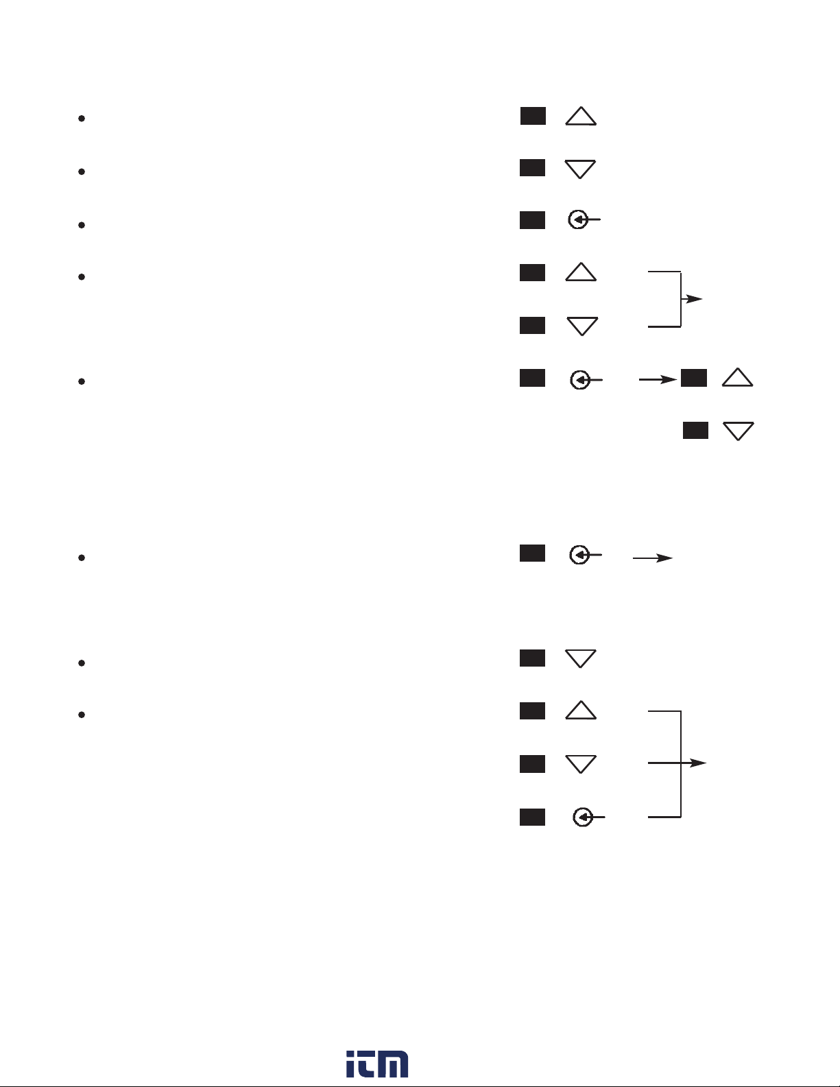
3.1. Adjusting temperature
The digital display (3) normally indicates the actual
temperature. The digital display (3) switches to the current
setpoint when the ”UP” or “DOWN” button (4) (6) is pressed.
The setpoint (flashing indication) can now be changed as
required by pressing or pressing and holding the ”UP” or
“DOWN” button (4) (6). If the button is pressed and held
down, the setpoint changes quickly. Approx. 2 sec. after the
button is released, the digital display (3) automatically
switches back to the actual value.
3.2. Manual heating shut down (OFF)
The device heating is shut down by simultaneously pressing
the ”UP” and “DOWN” buttons. "OFF" appears on the
display (3). If the standby function is also active, the
temperature is reduced to 65°C (150°F). “Stb” appears on
the display (3).
3.3. Adjust Temperature-OFFSET
The real surface temperature can be readjusted in a
± 40°C (± 72°F) OFFSET range.
1. Press key for special function (8). Display (3) show 000
2. Set Auto-OFFSET-temperature value with key ”UP” or
“DOWN”. After 4 sec. the Display switch back to actual
value.
3.4. Automatic heating shut down (AUTO OFF function)
The auto off time for the heating shut down is displayed
flashing by pressing and holding (approx. 3 sec.) the key for
special function (8). The shut-down time can be adjusted in
5 minute steps in the range 5 - 600 min by pressing the
”UP” or “DOWN” button (4) (6). A setting of less than 5 min
switches off the automatic heating shut-down and "OFF"
appears on the display (4).
If the standby function is also active, the temperature is
reduced to 65°C (150°F). “Stb” appears on the display (3).
3.5. Operation using RS232 serial interface
When operated together with the WHA 3000P / WHA 3000V
hot air station, the WHP 1000 heating plate is controlled via
9
English
www. .com information@itm.com1.800.561.8187

10
English
the RS232 serial interface (10).
Here the heating plate is used as a bottom heater for
electronic assemblies and is integrated into a 3-step
temperature-time profile.
When used in automatic mode (Remote LED (1) illuminated)
it is not possible to make any entries directly at the heating
plate.
The temperature setting is made via the WHA 3000P /
WHA 3000V hot air station.
When the program is not active, the heating plate is switched
off. "OFF" appears on the display (3).
If the standby function is also active, the temperature is
reduced to 65°C (150°F). “Stb” appears on the display (3).
3.6. STANDBY function
In standby mode the temperature is reduced to 65°C (150°F)
if a heating shut-down occurs (using OFF, AUTO OFF, RS232).
The standby mode is activated via a “Power-On Routine”.
For this purpose the device is first switched off at the mains
switch (5). Press the key for special function (8) and switch
on the device. Keep button pressed until the - 1 - appears on
the display (3). When the key for special function is released
the setting is saved. The standby function is switched on.
Use the same procedure for switching off. - 0 - appears on
the display (3) (factory setting).
4. Operation with external Sensor
It is also possible to measure the control variable for the
temperature regulation using an external sensor. If an
external sensor is connected, the current temperature from
the external sensor is displayed and controlled instead of the
temperature of the heating lamps.
The external sensor, an insulated thermocouple type K, is
connected to socket (9). LED (2) on the display (3)
illuminates.
Note:
The sensor must be adequately in contact with the
assembly or component for correct operation. When
working with the external sensor, the temperature
setting (setpoint) must be adjusted to suit the measuring
point.
5. Error indications on the display (3)
- - - No temperature sensor detected
E10 Maximum housing temperature exceeded
6. Other power-on routines
°C / °F change over
For this purpose the device is first switched off at the mains
switch (5). Press “DOWN” button (6) and switch on the devi-
ce. Keep button pressed until the “°F” appears on the display
(3). When the “DOWN” button is released the setting is
saved. Use the same procedure for the change over to “°C”.
Resetting to the factory setting (FSE)
For this purpose the device is first switched off at the mains
switch (5). Press “UP” (4) + “DOWN” (6) + key for special
function (8) simultaneously and switch on the device. Keep
buttons (4, 6, 8) pressed until "FSE" appears on the display
(3). When the buttons (4, 6, 8) are released the setting is
saved.
7. Accessories
External sensor type K (0.5mm) 5 31 190 99
Interface cable 5 31 191 99
WBH2 Circuit board holder 5 33 167 99
WBHS Circuit board holder with stand 5 33 165 99
WHA 3000P Hot air station 5 33 346 99
WHA 3000V Hot air station 5 33 366 99
8. Items supplied
WHP 1000 heating plate
Mains cable
Operating instructions
Safety information
Circuit Diagram, see page 47
Exploded Diagram, see page 48
Subject to technical change without notice!
See the updated operating instructions at
www.weller-tools.com.
www. .com information@itm.com1.800.561.8187

47
Circuit Diagram
www. .com information@itm.com1.800.561.8187

48
Exploded Drawing
www. .com information@itm.com1.800.561.8187

Weller®is a registered Trademark and registered Design of Apex Tool Group, LLC
© 2014, Apex Tool Group, LLC
T005 57 172 06 / 12.2014
T005 57 172 04 / 10.2012
www. .com information@itm.com1.800.561.8187
Other manuals for WHP 1000
1
Table of contents
Other Weller Cooktop manuals
Popular Cooktop manuals by other brands

Inalto
Inalto ICI30T.1 quick start guide

GE
GE PP912KMCC Dimensions and installation information

Frigidaire
Frigidaire FFGC3625LB Product specifications

Frigidaire
Frigidaire FEC32S6H Factory parts catalog

Bartscher
Bartscher 114356 Original instructions

Gaggenau
Gaggenau CK 481-6 Series Operating and assembly instructions