Wells-Gardner 19K4901 User manual

\I!
.,
e !!I
WElls-GAR<INER
E~ics
CORPORATION
---------------------
19"
IN LINE COLOR MONITORS
MODELS
19K4901
19K4902
19K4903
19K4906
19K4911
MODEL
19K4904
MODELS
19K4951
19K4952
19K4953
19K4956
19K4956R
19K4961
~
~
.
~
2701
NORTH KILDARE AVENUE
CHICAGO,
ILLINOIS
IOl3t

' .
THIS
MANUAL
APPLIE.S TO THOSE MONITORS WITH SERIAL NUMBERS
OF
576001
AND ABOVE.
WARNINGS
1.
Power Up
Warning-
An Isolation transformer must be used between
the
AC supply and
the
AC
plug
of
the
monitor
beforeservicing
or
testing
Is performed since
the
chassis and the heat sink are directly connected
to
one side
of
the
AC
tine which could present a
shock hazard.
Before servicing Is performed, read
all
the
precautions labelled on the CAT and chassis.
2.
I X-RAY RADIATION WARNING NOTICE I
WARNING: PARTS
WHICH
INFLUENCE
X-RAY RADIATION IN HORIZONTAL DEFLECTION,
HIGH
VOLTAGE CIRCUITS ANO
PICTURE TUBE ETC. ARE INDICATED
BY
(*)IN
THE PARTS LIST FOR REPLACEMENT PURPOSES. USE ONLY
THE
TYPE
SHOWN IN
THE
PARTS LIST.
3.
High
Voltage-
This
monitor
contains
HIGH VOLTAGES derived from power supj:)lies capable
of
dellverlng LETHAL quantities
of
energy.
Do not
attempt
to
service
until
all
precautions necessary
for
working on HIGH VOLTAGE equipment have been observed.
4.
CRT
Handling-
Care must be taken not
to
bump
or
scratch
the picture tube as
this
maycause the picture
tube
to
Implode resulting
in
per-
sonal Injury. Shatter
proof
goggles
must
be
worn when handling
the
CAT. High voltage
must
be completely discharged
before handling.
Do
not
handle
the
CRT
by
the
neck.
5. I PRODUCT SAFETY NOTICE I
WARNING: FOR CONTINUED SAFETY REPLACE SAFETY CRITICAL COMPONENTS ONLY WITH MANUFACTURER
RECOMMENDED PARTS. THESE
PARTS
ARE IDENTIFIED
BY
SHADING AND BY
(.ti.)
ON THE SCHEMATIC DIAGRAM.
AVERTISSEMENT:
POUR
MAINTENIA
LE
DEGRE
DE
SECURlTE
OE
L'APPAAEIL NE REMPLACER
LES
COMPOSANTS
DONT
LE
FONCTIONNEMENT
EST
CRITIQUE
POUR
LA SECURITE QUE PAA DES PIECES RECOMMANDEES PAA
LE
FABRICANT.
Forreplacement purposes, use
the
same
type
or
specified type
of
wire and cable, assuring the positioning
of
the wires is
followed (especla\ly
for
H.V.
and power supply circuits). Use
of
alternatlve wiring
or
positioning
could
result
In
damage
to
the monitor
or
In
a shock
or
fire
hazard.
PERFORMANCE AND OPERATING DATA
1.
Apply a
suitable
power source
to
the
monitor
through an isolation transformer.
2.
Apply a
suitable
signal source
to
the
monitor
PCB by means
of
P201
and
P202
3.
Set Up Controls.
All
controls
are preset
at
the factory,
but
may be adjusted
to
suit
program materlal.
1.0 Supply
Voltage 108 VAC-132
VAC
Frequency 50 Hz-60 Hz
Note: Apply supply voltage through an Isolation transformer
with
1 Amp. minimum capablllty.
2.0
High
vot
..
ge
(EHl)
For 19"V models 24.3 ± 0.8
K.
V.
at OBeam;
Note:
Condition
for
above: A.C. = 120V
3.0
Senlce
Set-Up Controls
MAIN
PC
BOARD
3.1
Vertical
Hold
Control,
VR301
3.2
Vertical Size Control, VR303
3.3
Horizontal Hold Control,
VR351
3.4
Vertical Raster
Position
Control,
VA
901
3.5
Horlzontat Raster Position Adjustment
Jumper
(3
positions)
3.6
Screen Control (Part
of
H.V.
Unit, T352)
3.
7
Focus
Control
(Part
of
H.
V.
Unlt,
T352)
3.8
Horizontal Width Coll,
l352
(L601
on
Model K4904)
3.9
Black
Level Control,
VR201
2
22.8 ± 0.8 K.V. at 1 mA Beam
3.10
Horlzontal Video Position Control,
(Horlzontal Shift)
VR352
3.11
Vertlcal Damping Control, VR302
NECK
PC
BOARD
3.12
Video Drive Controls,
Red
VR-401
Green VA402
3.13
CAT Cut
Off
Controls,
Red
VA403
Green VA404
Blue VR405

SERVICE
INSTRUCTIONS
NOTE:
All monitors are equipped with automatic degaussing
coils
(L701) which demagnetize the picture tube
every
time
the monitorIs turned
on
after
being
off
for a minimum
of
5 minutes. Should any part
of
the chassis
become magnetized
It
will be necessary
to
degauss the affected area with a manual degaussing coil. Move
the coil
slowly
around the
CRT
face area and all surrounding metal parts. Then slowly withdraw for adistance
of
6 feet before turning off.
Horizontal vs. Vertical:
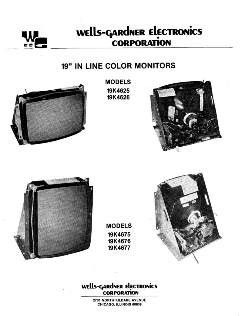
Some models have the picture tube mounted vertically rather than horizontally. That
Is,
the picture tube Is
mounted in the frame such that the long dimension
of
the tube Is up and down. Examples
of
this include(but
are not
limited
to) Models
K4951,
K4952,
K4956,
K4956R, and
K4961
as
In
the pictures on the bottom
of
the
front cover. Other than the physical orlentatlon
of
the picture tube, there Is
no
electrical difference between
these models and their horizontal counterparts. The same circuits, the vertical circuits, produce and control
deflection along the short dimension
of
the tube In all models.
The same circuits, the horizontal circuits, produce and control deflection along the long dimension
of
the
tube
In
all models.,Therefore, wherever "vertical" appears in this manual
or
on the monitor,
it
refers to the short
dimension
of
the picture tube; wherever "horizontal" appears,
lt
refers tothe long dimension
of
the picture tube.
1.0
BLACK
LEVEL CONTROL ADJUSTMENT
This control has been set at the factory and should not need further at-
tention. However, when the game is connected 3 slight adj1Jstment
of
VR201
may
be
necessary to obtain the proper black level (the black
portion
of
the picture just extinguished).
2.0 VERTICAL SIZE (HEIGHT)
Location
of
this control is shown in Fig.
1.
This control must
be
adjust-
ed
slowly,
If
necessary, until the picture or test pattern attains the cor-
rect vertical proportions.
NOTE:
This adjustment interactswith thevertical dampingadjustment
described in the paragraph below. Umay
be
necessary to readjust the
vertical size after the vertical damping control has been adjusted.
3.0 VERTICAL DAMPING
Adjustment
of
this control is required only if the monitoris being used
with a game in which the top several raster lines are visible
on
the
screen. Adjust the vertical damping control for uniform spacing
of
the
top raster lines.
4.0 CIRCUIT PROTECTION
A 4.0A ptgtall fuse, mounted on the Main Board has been provided to
protect the Power Output Circuit.
5.0 FOCUS
Adjust the Focus control, located on the
HV
unit(T352), for maximum
over-all definition and fine picture detall.
6.0 HORIZONTAL
HOLD
CONTROL ADJUSTMENT, VR351
(See
Fig.
1a
or
1b)
A warm-up period
of
at
least five minutes should
be
allowed before
alignment is carried out. With the monitor being driven from the
game signal, short
TP601
to
TP31.
Adjust
VR351
until the picture
stops sliding horizontally. Remove the short.
7.0
HORIZONTAL
VIDEO POSITION
If
the video is
off
center on the raster, some compensation can be
made by adjusting
this
control.
8.0 VERTICAL RASTER POSITION ADJUSTMENT
If
the video Is
off
center vertically, (short dimension
of
picture tube)
some compensation can be made by turning the vertical raster posl-
tlon control.
9.0 HORIZONTAL RASTER POSITION
ADJUSTMENT
If the video
Is
off
center horizontally (long dimension
of
the picture
tube), somecompensationcan be made by moving thehorizontal ras-
ter position adjustment jumper to either positions
"A"
or
"L".
NOTE:
This adjustment Is not provided on Model
K4903.
10.0 HORIZONTAL WIDTH ADJUSTMENT
The
horizontal width coll ls a hexagonal tuning tool adjustment. This
control must
be
adjusted slowly,
If
necessary, until the picture
or
test pattern attains the correct horizontal proportions.
3
...
..
,
..
ltt:D CUTO,ir
...
cvro,,:-\
ILU
CUTOFF\
'\
.
..
...
,m
DftlVE
_,,
WIDTH
COIL
H01tl2 Yt:ltT Yt:ltT
VIIIT
vt:ltT
HOllll
SClttEN
CIENT!ltlNG
Silt:
HOLD DAMPING IIASTl!:lt ltASTl!lt
POI.
SMln-lf
*NOT
ON
MOOl!L
IC
◄
IOl
ltl!O
CUTOFI'
...
""
...
...
Figure 1(a)
Gllfll
ltro
ORIYI: O!tlVE
..
,.,
WHEN USING
COM-
POSff'E
SVIIC
USE
HOltllONTAL
STNC
INPUTS.
""--·
ILIC
LIVl!L
At"""
,...,
HOltlZ
WIOTH
,~,
HOltlZ
YIEIIT
Yt:IIT
\ll!ltT
VlltT
ltOltll
SCltHN
CINTOt"'°
SIU
NOLD
OAIIIIP-
ltAITt:lt
IIAITl!lt
P'OS.
IHln
Flgure
1(b)
INSTALLATION AND SERVICE INSTRUCTIONS
NOTE: All
of
the
followlng procedures have been performed
at
the
factory
and
should
require no further
attention.
If
the
monitor
is serviced for any reason, it should
be
observed afterward to determine whether
any
of
these procedures need
to
be performed again.
OUTLINE
OF
CONVERGENCE AND SET-UP
PROCEDURE
1.0 DEGAUSSING: Demagnetize the shadow mask and
all
surrounding metal parts
with
an external degaussing
coil.
2.0 PURITY:
Adjust
the
purity
magnets
aAd
the
yoke position.
3.0
STATIC
CONVERGENCE: Converge
Red
and Blue on
Green
In
the
center
of
the screen.
4.0 DYNAMIC CONVERGENCE: Converge
Red
and Blue at
the edges
of
the screen.
5.0 WHITE BALANCE:
Set
Gray and
White
brightness track-
ing.
NOTE: Number 2.0 and 3.0
adjustments
interact.
1.0 DEGAUSSING
The
monitor
Is equipped
with
an automatic degaussing
circuit. However,
if
theCRT shadow mask has become ex-
cessively magnetized,
It
may be necessary to degauss
it
with a manual coll. Do not
switch
the coil OFF while the
raster shows any effect from the coil.
2.0 COLOR PURITY ADJUSTMENT
2.1
For best results,
it
Is recommended that the purity ad-
justment be made in the final monitor location.
If
the
monitor will be moved, perform this adjustment with It
facing west
or
east. The monitor
must
have been
operating
15
minutes prior
to
this
procedure.
2.2
Set the converger assembly on the CRT neck
with
the
center
line
(of the Purity Adjustment Magnet) over the
gap between grids no. 3 and
4.
(See Figures 2 and
6)
2.3
Make certain
that
themagnetic ring-pairs are intheircor-
rect positions before starting procedure.
This produces a zero-correctlon condition on the CRT
beam and helps
facilitate
adjustments.
2.4
Vertlcal raster position control must be at the center
of
its
rotation.
2.5
Remove the
R-G-B
signal from the monitor.
2.6
Turn the Green Cut
off
Control
(VR404)
on the Neck
Board
fully
CW.
(See Fig.
3)
2.7 Turn the
Red
and Blue Cut
off
Controls
(VR403
& VR405)
fully
CCW.
2.8 Pull the DeflectIon Yoke backward so
that
theGreen belt
wlll appear. (See Fig.
4)
2.9
Decrease
the
horizontal
width
of
the raster,
if
necessary,
in order
to
be
able
to
see the right and
left
edges
of
the
raster.
2.10
Move the
two
Purity Magnets
with
respect to each other
In
order
to
center the raster horizontally on the screen
and the Green belt on the raster horizontally.
2.11
Push the Deflectlon Yoke forward gradually and fix
It
at
the place where the Green screen becomes uniform
throughout.
2.12
Turn the Cut
off
and Drive Controls and confirm that
each
color
Is uniform.
2.13
If
the
color
Is
not
uniform, re-adjust It, moving the Purity
Magnets slightly.
4
TOP
VIEW
.....
VIEW
RED/BLUE
OH
GREEN
10 o"CLOCI<
--
-
----rf:10S
NO.
3AND
41
p
0
s
'
T
'
0
N
'
N
G
J...,,,,-,
AO,.
--
RED/BU.IE ADJ.
;.;;.;;l----
RED/BLUE
OH
GREEN
ADJ.
REO/BWE
2 O'CLOCK
CONCENTRIC
CONVERGER ASSY.
SHOWN
IN
ZERO
CORRECTION POSITION.
PURI PURITY
9 O'CLOCK 3
O'CLOCK
FIGURE2
INDIVIDUAL
TAB
ROTATION
FIGURE
3:
Component
Side
of
Neck
Board
{with horizontally mountedCRT)
FIGURE
◄

2.14
Turn
all three cut
off
controls fully counterclockwlse
(CCW).
Slowly turn
up
(CW)
the
Red
cutoff control until a
Red
raster
is
just barely visible.
2.15
Slowly turn up the Green and Blue cutoff controls such
that their associated colors, mixing with the
Red,
results
in a White
or
Gray raster.
2.16
Confirm
that
the white or gray color is uniform
throughout the screen.
2.17
Insert a wedge temporarily as shown
In
Fig. 4and adjust
the angle of the Deflection
Yoke.
3.0 STATIC CONVERGENCE ADJUSTMENT
4-Pole Magnets and 6-Pole Magnets are for static
convergence. "
3.1
A cross hatch signal should
be
connected
to
the
monitor.
3.2
A
pair
of
4-Pole Convergence Magnets
Is
provided
and adjusted to converge the blue and red beams
(See Fig.
6).
When the Pole opens to the left and
right
45
° symmetrically, the magnetic field maxi-
mizes.
Red
and blue beams move to the left and
right
(See
Fig.
5).
Variation
of
the angle between
the tabs adjusts the convergence
of
red
and blue
vertical lines.
3.3
When both 4-Pole Convergence Magnet Tabs are
rotated as a pair, the convergence
of
the red and
blue horizontal lines Is adjusted.
3.4
A
pair
of
6-Pole Convergence Magnets
ts
also pro•
vlded and adjusted to converge the magenta (red
+ blue) to green beams
(See
Fig.
6).
When the
Pole opens to the left and right 30" symmetrlcalty,
the magnetic fleld
Is
maximized.
Red
and blue
beams both move to the left and right
(See
Fig.
5).
Variation
of
the opening angle adjusts the con-
vergence
of
magenta
to
green vertical lines.
3.5
When both 6-Pole Convergence Magnet Tabs are
rotated as a pair, the convergence
of
magenta to
green horizontal llnes is adjusted.
VERTICAL
CONVERGENCE
91.UEtl
RED
Git£(!'(
GUIii
ts
fflE
CENTER GUI'(.
CQll(VEINJE
THE
MD
AND
ILUE.
THEN
CONVEIISE
ltED
ANO
IL.Ut:
ON
GREEN.
, '
'
'
'
'
'
, BLUE
to--
'
'
'
'
SLIDE MAGNETIC
RING
TASS
TOWARD
OR
AWAY
FROM
EACH
OTHER
HORIZONTAL
CONVERGENCE
81..UE
fl
RED
VERTICAi.
CONVERGENCE
BLUE
a R£D
ON
GREEN
•
••
HORIZONTAi.
CONVERGENCE
IWEtl
RED
ON
GREEN
•••
law£
----
___
t _---------
ROTATI:
BOTH
MAGNETIC
RINGS TOGETt4ER
&-POLE
.....
,.
=
0
•••
:REO/BLU
H
ROTATE BOTH MAGNETIC RINGS TOGETHER
•
REPEAT
3.2
8
I.I
IF lll.L
LINE$
ARI
NOT
CONVUfGED
AT
CENTER
5827
FIGURE5
----
• -
-----ANOOE
CONTACT
•
FIGURES
~-
CONVERGENCE
4
POLE
CONVERGENCE
MAGNETS MAGNET ASS'
6
POLE
CONVERGENCE
MAGNETS l
-PURITY
CENTERING
MAGNETS V
OEFLECTION
YOKE
'-----------
RUBBER WEDGES
5

' .
4.0 PRECISE ADJUSTMENT
OF
DYNAMIC
CONVERGENCE (See Fig. 7, 8 and
9)
R
G
8
4.1
Feed a cross hatch signal to the monitor.
4.2
Insert a wedge temporarily and fix the Deflec-
tion Yoke so as to obtain the best circumfer-
ence convergence (See Fig. 8 and 9)
NOTE:
The wedges
may
need
to
be moved during ad-
justments.
4.3
Insert three rubber wedges to the posltlon as
shown in Fig. 7 to obtain the best circumfer-
ence convergence.
NOTE:
1)
Tilting the angle
of
the yoke up and down ad-
justs the crossover
of
both vertical and hori-
zontal
red
and blue llnes. See Fig. 8
(a)
and
(b).
2)
Tilting the angle
of
the yoke sideways adjusts
the parallel convergence
of
both horizontal
and vertical lines
at
the edges
of
the screen.
See
Fig. 9
(a)
and
(b).
3)
Use three rubber wedges (tapered rubber
wedges are used for a purpose).
4)
The
position
of
each rubber wedge is shown in
Fig.
7.
5)
Do
NOT force the permanent wedges in. They
are
to
be Inserted until
they
Just make
contact
with
the
yoke-after
the yoke has been posi-
tioned.
6) Fix the three permanent rubber wedges
with
chloroprene rubber adhesive.
7)
After
the adhesive has dried enough
to
hold
the wedges in place,
carefully
remove the tem-
porarily
installed
wedge.
UPPER
B G R
~
' I 8
G
R
I I
R G 8 UNDER
CRT
SCREEN
lo)
INSERT RUBBER
WEDGE
FROM UPPER SIDE
•
G
R
FIGURES
CRT
SCREEN
(a)
INSERT RUB BEA WEDGE
FROM
LEFT
SIDE
FIGURE9
6
R G •
'
e'
R
CRT
SCREEN
CRT
SCREEN
TEMPORARILY
INSTALLED
WEDGE
FIGURE7
R
G
I
,.,
,o,
R 8
"I
UPPER
CRT
DY
1
UNDER
INSERT RUBBER WEDGE
FROM LOWER
SIDE
(b)
INSERT
RUBBER
WEDGE
FROM
RIGHT
SIDE

5.0 WHITE BALANCE
5.1
Equipment Required: An oscilllscope
with
a
DC
coupled mode In the vertical amplifier,
or
a
dlgltal
multimeter,
or
a
VOM
with
a
DC
Input
Impedance
of
at
least 20,000 ohms/volt.
5.2
Referring to Fig.
1(a)
or
1(b)
and
3,
do the
following
adjustments
In subdued
light
after
degaussing and setting the purity
of
the
CRT.
5.3 Ground the R/G/8 video inputs.
5.4 Set the Red and Green drive controls, VA401
and VR402,
to
approximately
80¾
of
full CW
rotation.
5.5
Set the screen and R/G/B
cutoff
controls
to
their
minimum
(fully CCW) positions.
5.6
Connect the oscilloscope, multimeter,
or
VOM, to
the
collector
of
a video output tran-
sistor
(0401, 0402, or 0403) on the CRT neck
PCB at TP47R, TP47G, or TP47B
as
shown
in
Fig. 3.
5.7 Adjust the
black
level control
(VR201)
to
ob-
tain
the waveform shown in Fig.
10
or
a +150
volt
DC
reading
on
the multimeter
or
the VOM.
5.8 Slowly turn the screen control CW until
the
raster is
just
visible. The color
of
this
raster
Is
called
the
lead
color
gun.
DO
NOT adjust
Its
associated
cutoff
control. II must remain
fully
ccw.
5.9 Adjust thescreen
control
CCW
until
the
raster
is Just extinguished. Then
adjust
the
black
level control
for
a dim raster.
5.10 Adjust the
two
remaining
cutoff
controls(NOT
the lead color gun
cutoff
control) for best gray
uniformity.
5.11
Adjust the
black
level
control
for a bright
raster
but
not
maximum brightness. Adjust
the
RIG
drive controls,
If
necessary, for best
neutral white.
5.12
Repeat steps 5.10 and
5.1
i
until
good
tracking
of
white
balance is achieved.
5.13 With the oscilloscope, multimeter,
or
VOM
connected
to
the
collector
of
the lead
color
video output transistor (See Fig.
3),
adjust the
black
level
control
to obtain the waveform In
Fig.
10
or
a +150 volt DC reading on the
multlmer
or VOM.
BLANKING PULSES
140V
---------~l~o-voc
FIGURE
10
7

Ref. No.
"''"
R202
R203
"'°'
R205
"""
R207
R206
R209
fl210
R211
"'"
R215
R216
"'"
"'"
fl219
R220
"'"
"'"
"'"
R225
R226
""'
R228
"'"
R230
R231
R232
R233
R234
R235
R236
R301
R302
R303
R304
"""
R306
R307
R309
R310
fl311
fl312
R313
R314
R315
fl317
fl318
R319
R320
R32(
R322
""'
R3S2
R353
""'
R355
R358
R380
R381
R362
*R363
R364
R365
R367
R366
"""
Part
Mo.
REPLACEMENT PARTS LIST
MODELS
K4901,
K4906, K4951, and K4956
This
monitor
contains circuits and components Included specifically
for safety purposes.
For continued protection no changes should
be
made to the original
design, and components shown
In
shaded areas of schematic, or
&.*
on parts
11st
should be replaced with exact factory replacement parts.
The use
of
substitute parts may create a shock, fire, radiation
or
other
hazard. Service should be performed by qualified personnel only.
MAIN
BOARD
-~
..
1191.
Mo.
hrtHo.
_
..
RESISTORS RESISTORS (Cont.}
203X6500-645
1K Ohm,
5%,
1/,IW Carbon
A370
203X6501-002 33K Ohm,
5%,
114W
Carbon
340X2331-934
330 Ohm,
5%,
114W
Carbon
A371
203)(9()14-584 1K Ohm,
5%,
1W
Metal
Oxide
203X6500-405
100 Ohm,
5%,
1/4W Carbon R372 203X9104-809 12K Otlm,
5¼,
'1!i'J
Metal
Oxide
203X6700-327
100 Ohm,
5¼,
112W
Carbon A375 203X9014-724 3.9K Ohm,
5%,
1W
Carbon
203X870CM21 270 Ohm,
5%,
1!ZW
Carbon A376
203X9104-4CM
270 Ohm,
5%,
M Metal
Oxide
200)(651)1)..5-'0 390 Ohm,
5"1o.
1/4W Carbon R377 203X6500-447 150 Ohm,
5%,
1/
◄
W
Carbon
340X2221-93
◄
220 Ohm,
5%,
114W
Carbon
A378
203X6500-886
10K
Ohm,
5%,
1/
◄
W
Ga.rbon
203)(6,00.5'0
390 Ohm,
5%,
1/
◄
W
Carbon
"""
203X__,,.
10K
Ohm,
5%,
1/
◄
W
Carbon
340)(2221-93
◄
220 Ohm,
5%,
1/
◄
W
Carbon
R380 203X6500-865 8.2K Ohm,
5%,
1/
◄
W
Carbon
203X6500-5◄0
390 Ohm,
5%,
114W
Carbon
R381
203X6500-72
◄
2.2K Ohm,
5%,
1W Metal
Oxide
340)(2221-934 220 Ohm,
5%,
1/4W
carbon
R383
203X9014-387 150 Ohm,
5%,
1W Metal
Oxide
203X6500-645 1K Ohm,
5%,
1/
◄
W
Carbon
A384
203)(6501-088 68K Ohm, 51/.,
114W
Carbon
203X6501-126 100K Ohm,
5%,
1/
◄
W
Carbon
A385
3
◄
0X2122-93
◄
1.2K Ohm,
5%,
1/
◄
W
Carbon
203X6500-6-45
1K
Ohm,
5%,
1/
◄
W
Carbon A387
340)(2224-93
◄
220K Ohm,
5%,
1/
◄
W
Carbon
203X6500-<05 100 Ohm,
5%,
1/
◄
W
Carbon
R3811
3
◄
0X5183'633
18K Ohm,
5%,
ffi
Metal
Oxide
203X6500-645
1K
Ohm,
5%,
1/
◄
W
Carbon
A390
3◄
0X
◄
222-633
2.2K Ohm,
5%,
1W Metal Oxide
203X6501-126 100K
Ohm,
5%,
1/
◄
W
Carbon
A502
203X__,,.
10K
Ohm,
5%,
1/
◄
W
Carbon
203X6500-645
1K
Ohm,
5%,
1/
◄
W
Carbon
A503 204X1700-535 150 Ohm,
5%,
15W Metal Oxide
203X6500-405 100 Ohm,
5%,
1/4W
Carbon
-203X9014-267 47 Ohm,
5%,
1W Metal
Oxide
203)(6500-762 3.3 Ohm,
5%,
1/4W
Carbon
R505
203X6501-209 220K Ohm,
5%,
114W
Carbon
203X6500-169 10 Ohm,
S¾,
114W
Carbon R506 204X1425-196 15 Ohm,
5%,
SW
Wire Wound
203X6500-169 10 Ohm,
S¾,
114W
Carbon
A507 203X5602-185 330K Ohm,
5%,
112W
Comp.
203X6500-189 10 Ohm,
SO/o,
114W
Carbon
A*
R601
204Xt625-058 3.3 Ohm,
5%,
10W WW
203X6501-044
◄
7K
Ohm,
S¾,
1/
◄
W
Carbon
R701
203)(9105-141 2.2 Ohm,
S¼,
ffi
Metal
Oxide
340)(2152-93
◄
1.5K Ohm,
5%,
114W
Carbon
A702 203X6206-441 2.2 Ohm,
SO/o,
112W
Carbon
203X670CM21
270
Ohm,
5%,
1!ZW
Carbon
VR201
204X2070-0n
2K
Ohm-B Semi-Fixed
203X6500-863 8.2K Ohm,
5%,
112W
Comp.
VR301
204)(2070-08
◄
SK
Ohm-B Semi-Fixed
203X6500-863 6.2K Ohm,
5%,
112W
Comp. VR302
204)(2070-06
◄
SK
Ohm-B
Semi-Fixed
203X6500-863 8.2K Ohm,
5%,
1/ZW
Comp. VR303 204X2070-055 500 Ohm-B Semi-Fixed
203)(6500-468
180 Ohm,
5%,
1/
◄
W
Carbon
VR351 204X2070-072
2K
Ohm-B Semi-Fixed
340X2820-93◄
82 Ohm,
5%,
114W
Carbon
VR352 204X2070-072
2K
Ohm-B
Semi-Fixed
3'())(282().934
82 Ohm,
51/o,
1l
◄
W
Carbori
340X2820-93◄
82
Ohm, 5'/o,
1/
◄
W
Carbon
CAPACITORS
203X6500-508 270
Ohm,5%,
1/
◄
W
Carbori
203"6500-863 &2K Ohm,
5%,
114W
Carbori
c201
203X0014-086 1000
uf,
16V, Electrolytic
203X6500-863 8.2K Ohm,
5%,
1/
◄
W
Carbon
C202
202)(7200-064 330
pf,
500V,
Ceramic
203)(6500-724 2.2K Ohm,
5%,
1/4W Carbori C203 202X7200-043 220 pF,
SOOV,
Ceramic
203X8500-842 6.8K Ohm,
5%,
1/4W
Carbon
0204
202X7200-043 220
pf,
SOOV,
Ceramic
203X6003-201 7.5K Ohm,
2%,
114W
Carbon
0205
203X0014-076 470
uf,
16V,
Electrolytic
203X6500-a25 5.6K Ohm,
5%,
114W
Carbon
C206 203X1810-149
0.1
uf,
125V Mylar
203X6500-965 22K Ohm,
5%,
114W
Carbon
0207
349)(2232-109 .022 uF, 100V Mylar
203X6500-988 39K Ohm,
5%,
114W
Carbon
C301 203X0014-065 330 uF, 50V Electrolytic
203X9014-709 3.3K Ohm,
5%,
1W
Carbon
0302
203X1600-563 .022 uF, 50V Mylar
203X9014-741
◄ .7K
Ohm,
5%,
1W Metal Oxide
C303
203)(0629-037 2.2 uF, 50V Electrolytic
204X1527-528
◄
70
Ohm,
5%,
7W
Carbon
C3(M
203X1600-366 .0068
uf,
50V Mylar
203X6500-481 220 Ohm,
5%,
1/
◄
W
Carbori C306 203X0412-012 2.2
uf,
16V Taritalum
203X6500-169 10 Ohm,
5%,
114W
Carbon
C307
203X1600-63
◄
0.033
uf,
50V
Mylar
203X6700-061 8.2 Ohm,
5%,
112W
Carbori C308 203X0025-163 2.2 uF,
50V
Electrolytic
203X6500-584 560 Ohm,
5%,
1/
◄
W
Carbon
C309 203X1207-100 0.068
uf,
100V
PP
203)(6500045
11<
Ohm,
5%,
1/
◄
W
Carbori C310 203X0629-061 10
uf,
100V Electrolytic
203X6501-002 33K Ohm,
5%,
1/4W
Carbon
C311 203X0041-162 4.7 uF, 160V.Electrolytic
203X6501-224 270K Ohm,
5%,
112W
Carbon
C312
202X7050-2
◄8
1000
pf,
508V
Ceramic
203X-
10K Ohm,
5•1o,
114W
Carbon
0313
203XO<M0-068
100
uf,
160V Electrolytic
203X-
10K Ohm,
5%,
1/
◄
W
Carbon
C314 203X1201-096 0.039 uF, 200V
PP
203X6500-78S 3.9K Ohm,
5%,
1/
◄
W
Carbori C315 203X0629-023 1
uf,
50V
Electrolytic
203X6501-088 68K Ohm,
5%,
1/
◄
W
Carbon
C35( 203X0629-023 1 uF,
50V
Elec1rolytlc
203X650CH62
3.31<
Ohm,
5%,
1/
◄
W
Carbori C352 203X0619-04S 47
uf,
25V
Electrolytlc
203X9205-143 6.8K Ohm, 51/,, 3W Metal Oxide C353 203)(1190-015 0.0082
pF,
50V Mylar-PP
340X3683-93
◄
68K Ohm,
5%,
1/ZW
Carbon
035< 203X0619-045 47 uF,
25V
Electrolytic
203)(6500-561 470 Ohm,
5%,
114W
Carbofl C355 203X1600-366 0.0066 pF,
SOV
Mylar
203)(850().888
10K Ohm,
5%,
1/
◄
W
Carbon
C358
203)(1130-287 0.0047
uf,
50V, Mylar
203)(9014-645 1.8K Ohm,
5%,
1W Metal Oxide C359 202X8065-606 100
pf,
500V
Ceramic
204X1450-516 3.9K Ohm,
5%,
5W Metal Oxide C360 202X7050-386 0.0033
pf,
500V
Ceramic
203X6500-246 22 Ohm,
5%,
114W
Carbori
036(
202X7050-483 0.01
uf,
500V
Ceramic
340)(2183-93
◄
18K Ohm,
5%,
114W
Carbon C362 202X7203-032 0.01 uF,
SOV
Ceramic
203X
.......
10K Ohm,
5%,
114W
Carbon
&.*
C363 203X1270-911 8100 pF, 1.5
KV
PP
203X5602-185 330K Ohm,
5%,
112W
Comp. C365 203)(1201-265 0.33 uF, 200V
PP
203X5602-329 680K Ohm,
5%,
112W
Comp. C366 203)(0019-026 22 uF,
25V
Electrolytic
8

.......
c.167
C368
C369
C372
C373
C380
C381
..
C501
..
C502
•coo,
..c.,.
C505
C506
c.,,
C701
C702
C703
0203
0204
0205
0206
0207
0208
0209
0302
0303
030<
0305
0306
0307
.:h
0501
1,.0502
..
0503
"°'°'
0505
0505
0701
0702
0201
0202
R401
R402
R403
"""
R405
R406
R407
"'°'
R409
R410
R411
R412
A413
R41-4
R415
R418
A419
"''°
R'21
VR401
VR402
VR403
v,,.,.
VR405
VR901
..
or·u•
•
__
...,.,
•-
\""'"""''"
••I
Pert No. Rel.No.
CAPACITORS(Cont.)
202X8086-182 6 pF, 500V
Ceramic
0"'3
202)(7203-032
O.
I uF,
50V
02!M
203)(1207-087 0.047
uF,
100V,
PP
0205
203)(1207-125 0.1
uF,
100V PP
0208
203X0020-021 1
uf,
50V,
Electrolytic
0207
202)(7200-087
-470
pF,
500V
Ceramic
0208
O!X"""°"
-470
pF,
500V,
Ceramic
0209
203)(1810.149
0.1
uF,
125V
Mylar
0210
202)(7050-282
1500
pF, 500V
Ceramic
0301
202)(7810.21-4
2200
pF, 125V
Ceramic
0302
202)(7810.21-4
2200
pF, 125V
Ceramic
0303
203)(0220-075
_560
uF,
200V
Electrolytic
0351
203X'°"""'
~~
uF,
180V
Electrolytic
0352
203X00-41-057 ·47
uF,
180V
Electrotytlc
ZD301
203X0019-092
1000
uF,
25V
Electrolytic
IC30t
203X063-4-061
10
uF, 100V
Electrolyllc
~*tC501
202)(7050-2-48 1000 pF,
500V
Ceramic
SEMICONDUCTORS
■
L.351
*L.352
201X2010-159 01009, 152076-27 L701
201X2010.159
Diode,
IS2076•27 T351
201X2010-159 DIOIH, 152078-27
4.*T352
201X2010.159 Diode, IS2076-27
201X2010.159 Diode, IS2076-27 ■
L.351
201X2010.159 Diode, 1S2076•27
201X2010-159 Diode, 152076-27
201X2010.t59
Diode,
152076-27
AF501
201)(2010.159 Oiode, 152076-27 J402
201)(2120-009
Diode,
RH•IV P201
201)(2120-009
Diode,
AH•IV
P2D2
201)(2010.159
Diode,
1S2076•27
201X2010.165 Diode, ISS81 P401
P501
201)(3120-216 Diode, RM-1AV P001
201X3120-216 Diode, RM-1AV
201)(3120,216
Diode,
RM-1AV TH501
201)(3120-216
Diode.
RM•1AV
201X3120-216
Diode.
AM•1AV
201)(3120-216
Diode,
RM•lAV
201)(2130--23
◄
Diode,
AU-2V
201
X2120-009 Diode, AH•1V
200X3181-523
Transistor
(NPN) 2SC181SGR
200X3181·523
Transistor
(NPN) 2SC1815GR
NECK
BOARD
RESISTORS
203)(600().729
203)(85©540
203X6000--661
203)(600().729
"'3X""'540
203)(6000--681
203X6000-729
203X6000-998
203X6000.SS1
203)(9104-824
203)(9104-82-4
203)(9104,82-4
203X6000-998
203X6000-998
203X8000.s98
203)(9105·154
203X6501J.741
203)(850().7-41
203)(8500-741
204)(2115-01<1
20
◄
X2115-01
◄
204X2115-006
204)(2115-006
204X2115-006
220
Ohm,
5%
114W
Carbon
390
Ohm.
5%
114W
Carbon
820
Ohm,
5"/o 1/4W
Carbon
220
Ohm,
5%
1/
◄
W
Carbon
390
Ohm,
5¾
1/
◄
W
Carbon
820
Ohm,
5%
1/
◄
W
Carbon
47
Ohm,
5%
1/
◄
W
Carbon
270
Ohm,
5%
1/
◄
W
Carbon
820
Ohm,
5%
1I4W
Carbon
151<
Ohm,
5%
ZW M.O.
Fonnlng
15K
Ohm,
50/i,
'lW M.O.
Forming
15K
Ohm,
5%
2W M.O.
Fonning
2.7K
Ohm,
5%
1/'ZW
Comp.
2.7K
Ohm,
5%
112W
Comp.
2.7K
Ohm,
5¾
1/'ZW
Comp.
2.2
Ohm,
5%
'NI
Metal
Oxide
2.7K
Ohm,
5%
1/
◄
W
Carbon
2.7K
Ohm,
5%
1/
◄
W
Carbon
2.7K
Ohm,
5%
1/
◄
W
Carbon
500 Ohm,
-8
Seml•Fixed
500
Ohm,
-B
Seml•Flxed
5K
Ohm,
-B
Semi.fixed
5K
Ohm.
-B Seml..f"lxed
5K
Ohm,
·B
Semi.fixed
c,01
c,02
CMJ3
"""
C405
0401
0<02
0403
J401
'""
''°'
P701
P
■
rl
No.
SEMICONDUCTORS (Cont.)
200)(4()56.260
Translator
(PNP) 2SA562-Y•TM
200)(4()56.260
Transistor
(PNP) 2SA562-Y•TM
200)(4()56.26()
Transistor
(PNP) 2SA562-Y•TM
20())(3181•523
Transistor
(NPN) 2SC1815GR
200)(3181-523
Transistor
(NPN) 2SC1815GR
200)(3181-523
Transistor
(NPN) 2SC1815GA
200)(3181·523
Transistor
(NPN)
2SC1815GA
200)(3181·523
Transistor
(NPN) 2SC1815GA
200)(3181-523
Transistor
(NPN) 2SC1815GR
200)(3207-306
Transistor
(NPNJ 2SC2073LBGL2
200)(3207-306
Transistor
(NPN) 2SC2073LBGL2
200)(3248--217
Transistor
(NPN)
2SC2
◄
82BK
200)(-4589-602
Transistor
(NPN)
2S06988
66)(00-40-031 Diode,
Zener
24V,
3%,
112W
200X2300-033
IC
HA11423
200X2600-183
IC
STR381
TRANSFORMERS & COILS
201)(-4710.13
◄
Coll, (RF
Choke)
201)(5000-083
Coll,
Horlz. Sl:i:e
611)(0005-005
Coll,
Degaussing
202)(1300-080
Transfonner,
Hor.
Drive
200)(9720--301 HV-IJnlt M-11
Omitted
from
late
versions
MISCELLANEOUS
204)(7120-073 Fuse, 4
Amp.
125V
206X500a.632
Aecep
W
Wire
3P•M•BG
204X9800-
◄
66
Plug,
PWB
3P·J
204X9601-
◄
n
Plug,
PWB
8P·O
20
◄
X9600-296
Plug,
PWB 4P·B
204X9600-249
Plug,
PWB
2P·B
'°'x""°""'
Plug,
PWB
4P-C
201)(0100-112
Thermistor
FINAL ASSEMBLY PARTS
A*
88X0138-506 19VLTP22
Pix
Tube
205)(98()0.158
Lateral/Purity
Assembly
&,*202)(1111"258
Yoke
Deflection
or
202X1111-264
291)(5004-262
Automatic
Degaussing
Coll
Unit
CAPACITORS
202)(7050-269
202)(7050-2-48
202)(7050•248
202)(7050-282
202)(7050--483
1200 pF, 500V
Ceramic
1000 pF, 500V
Ceramic
1000 pF, 500V
Ceramic
1500 pF,
1.5KV
Ceramic
0.01
uF,
500V
Ceramic
SEMICONDUCTORS
200X3206000
200X,,....,,
200)(32()6.600
Transistor
(NPN)
2SC2068L8
Transistor
(NPN)
2SC2068L8
Transistor
(NPN)
2SC2068LB
MISCELLANEOUS
21l6X5009-296
204)(9801).254
2!MX96<J0.881
20-4)(96()1-020
204X9301-255
RE.CEP W
Wire
4P-E
Plug,
PWB
3P-A
Plug,
1 Pin
Plug,
PWB
◄
P-E
CRT
Socket
RESISTORS
VERTICAL
POSITION
BOARD
(P344)
SEMICONDUCTORS
-40)(0645-001
25K
Ohm
Vert.
Position
Control
0901 86)(0127-001
Transistor
(NPN) TPS98
9

REPLACEMENT PARTS LIST
.......
Pllrl
No.
...
...
MODELS K4902, K4952 MODEL K4903, K4953
Same as K4901, K4906, K4951, K4956 except: Same
as
K4901, K4906,
K
◄
951,
K4956 except:
C385
A389
l.151
A206
A208
A210
A229
C2<l2
C203
C204
R391
C365
C30l
R801
R802
A803
-
R805
0801
0801
0802
o$6X0536-021
0.27uf,
200V,
PP
Omitted from certain versions
of
these
models.
Omitted
from
late
versions.
C365
A389
L351
C385
MODELS K4911,
K4961
-46X0536-022 0.15 uF,
-400V,
PP
Omltlecl from these models.
Omltted
from
late
versions
of
these models.
Add the
tollowlng
to
late versions:
46X0536-037 820
pf,
1600V, PP,
5%
Same as K4901, K4906, K4951, K4956 except:
MAIN BOARD
RESISTORS
340X2221-93'4
340X2221-934
340)(2221-934
340)(3391-93-4
220
Ohm,
So/•,
114W
Carbon
220
Ohm,
5%,
114W
Carbon
220
Ohm,
5%,
1/-4W
Carbon
390 Ohm,
s•t.,
1rzw
Carbon
CAPACITORS
80X0099-020
80X0099-012
80X009!><l06
680
pf,
500V,
Ceramic
560
pF, 500V,
Ceramic
470
pf,
SOOV,
Cel"amic
L351
"""
c«J7
MODEL K4904
TRANSFORMERS AND COILS
Omitted
from
late
va111lona.
NECK BOARD
CAPACITORS
80X0090-020
80X0090-020
680
pf,
SOOY,
Ceramic
680
pf,
500V, Ceramic
Same as K4901, K4906, K4951, K4956 except:
MAIN BOARD
RESISTORS
340X221-934
220
Ohm,
5%,
1I4W
Carbon
L352
*L801
l.151
CAPACITORS
46X0536-025
46X05'40<M 0.56 uF, 200V,
PP
0.012 uF, 100V, PP
MODEL K4956R
TRANSFORMERS AND COILS
9"'2813-003
9A2822-001
Coll, Horlz. Lin.
Coll, Horlz. Size
Omitted
from
late
versions.
oJf.Same
as
K4901, K4906, K4956, except add
the
following:
RELAY BOARD
(P
340)
RESISTORS
340X2162-934
340X2473-934
340){2222-934
340X2514-934
340X2102-934
1.6K
Ohm,
5%,
1/4W
Carbon
47K Ohm,
5%,
1/4W
Carbon
2.2K
Ohm,
5%,
1/4W
Carbon
510K Ohm,
5%,
114W
Carbon
1K
Ohm,
5%,
1/4W
Cart:>on
SEMICONDUCTORS
66X0046-001
86X0113-001
86X0113-001
Diode,
Silicon
FDH-M-4
Translator (NPN) 2N3904
Kl!01
K802
J601
P802
P803
MISCELLANEOUS
2.A.0685-001
2A0886-001
3A0627-004
OA0393-004
_,
Relay, 12V, DPDT
Relay, 12V, DPDT
Socket, 4 Pin
Plug, 3 Pin, Right Angle
Plug, 4 Pln
*NOTE:
L351
omitted from
all
late '9rslons
of
all
models Included
In
/his manual.
10

OSCILLOSCOPE WAVEFORM PATTERNS
The
waveforms
areas observed on the
wide
band
oscilloscope
with
the
monitor
turned
to
a reasonably
strong
signal and a normal picture. The voltages shown on each waveform are the approximate peak amplitudes.
If
the waveforms are observed on the oscllloscope
with
a poor high frequency response, the corner
of
the
pulses
will
tend
to
more
rounded
than
those
shown
and
the
amplitude
of
anyhlgh
frequency
pulsewill tend
to
be
less.
A
2VfDIV 100uSECIDIV
TP-31
DC
COUPLED
BOTTOM
LINEaaO
VDC
2VIDlV 100uSEC/DIV
TP-31,
AC
COUPLED
0.5V/DIV 100uSECIDIV
IC 301/PtN 3
0.5V/DIV 5mSECIOIV
T,,.1
0.5V/01V 2mSECIDIV
20V/0IV 2mSEC/OIV
0.2V/OtV 20uSECIDlV
IC 301/PtN 13
1V/0IV
20uSECIOIV
IC
301/PIN 15
1VIDIV 10uSECIDIV
13
0351
COLLECTOR
20VIOIV 10uSECIDIV
D
2V/0IV 10uSECIDIV
J402-3
5V/DIV 10uSEC/OIV
1V/01V 2mSECIDIV
F
1V/DIV 100uSEC/DIV

*
Power
Suppty
Voltage and Symbol•
Symbol
Volt
■
te
Operating Circuit
-15V Vert. Osc.
Sync
Blanking
CRT Cut-Off
8 130V Horiz. Osc.
Horz. Drive
Horz. Output
Vert. Output
® 175V Video Output
CAUTION:
FOR
CONTINUED
SAFETY,
REPLACE SAFETY CRITICAL COM-
PONENTS ONLY WITH MANUFAC-
TURER'S RECOMMENDED
PARTS.
AVERTISSEMENT:
POUR
MAINTENIR
LE
DEGRE
DE
SECURITE
DE
L'APPAREIL
NE
REMPLACER
LES
COMPOSANTS
DONT LE FONCTIONNEMENT
EST
CRITIQUE
POUR
LA
SECURITE
QUE
PAR
DES
PIECES
RECOMMANDEES
PAR
LE
FABRICANT.
SERVICE TECHNICIAN WARNING
X-RAY RADIATION PRECAUTION:
: THIS PRODUCT CONTAINS CRITICAL
ELECTRICAL ANO MECHANICAL PARTS
ESSENTIAL
FOR
X-RAY RADIATION
PROTECTION.
FOR
REPLACEMENT PURPOSES,
ONLY
TYPE
PARTS SHOWN IN
PARTS LIST.
I
R301
2?0
IC301
·SYNC AMP \l08C
H.OSC
HAll423
ao22
C302l
I.
'10I
DEGAUSSING
COIL
(MY)
CJ04~
O.OOH
,...,,
MODELS 19K4901, 19K4906, 19K4951, 19K4956
·HOfflZ
.GNO
-VERT
C368
VR§I
I
H.
HOLD
I
o.,
8-2'<
(MY)
CM2
4?/25V
C90!~CS04
""""'""'~~~~
2
~=5V
.0041
r
CJH
OHi
HOR.DRIVE
ITP-atl
t
I ------------------
..
0401
RED
OUT.
2SC206a..8/LIBK
2SCl~l48VC1::VC
G~E1fSuT.
eY.~bJr.
29C2068LM.IIIC
2SC208L&\JB(
2SCISf48\,1C,CVC
2SClel4~
.__-<i~
51<
1t:l
2)
CA9P2)
~--!=='""-==-==t::~~----'ffl'---1i-.<~~{";~~;:
:j ,
/f
;
-1
.
L..-..lt~---ff9,(~I-E-}h,
.::j
<'.1
'.{
.
;,.'.,
0552
HOR.OtlT
29088;L
2908988
0304
.,..1ft+-elSS81
e
CENTER
L-t------'Wr--f~~~··'·;,,tf(,}t:/··•,···
W]
wJ
D701
ER824-04C
D
305
RIGHT
!HOR.CENTERING!
tSS81 R383 H.V.UNIT I
L 3&2
,,:p,
) T
3&2
C70t
-+
t000
/'l.GV
!HOR.SIZE!
* K
4901J,
K4906J.
K4951J
-
K4956G

PC
BOARD
LAYOUT
VIEW
OF COMPONENT SIDE
VIEW
OF
FOIL
SIDE
FIGURE
12
NECK
PC
BOARD
14

PC
BOARD
LAYOUT
HCD
-f,
,_
.-;
: {
17
0
a:
~
~
z
"
::E
u.i
0
iii
J
ii
IL
0
~
>
::?
w
a:
::,
S!
IL

I
'
R301
270
IC301
SYNC
AMP
\lOSC H.OSC
HAll423
F501
4A-1~\/
L 70I
1)1
DEGAUSSING COIL
Q
301
SYNC.AMP
2SCl81!5Y/Q.
Dc945
C302l
0.022
(MY)
C304l
0.00.8
(MY)
15
-HORIZ
GM)
-VERT
(368
VR30I I
H.
HOLD
I
o.,
B-2t<
(MY)
C3&2 A:!le,
4
7/'8,V
8.8t<
~SP
3)
C~3~C~4
2200P
/12~1/
MODELS 19K4902, 19K4952
r
CS56
.0047
0351
HOR.DRIVE
2SC24828K.
'2Sc
261081<
.---------------------
Rfo
4
iT
GR~Et
0
&JT
e'l~k
2SC206a..B/LSBK 29C2068LBll.9BK 2SC2061LM.SBK
2SCl~l4BVCltVC
2SCISC4BVC,tVC
2SC~48V~\IC
.,__..,..
1
Q3!52
HOA.OUT
2S0869
2S08988
IVERT. DAMP I
CSU
IVERT. SIZE f
100,~
0303
~\ERT.OUT
~29C20
•
SIOK
HOK
CRC1/2) CRC1/Z)
C365
I
0,21
,200
(PPI
W]
[y]
0
30~
RIGHT
)HOR.
CENTERING)
ISS81
R383
R.V.UNl'r
L
3~
.
(R'ii,
1 T 3!52
IHOR.StZEI
01'01
ER824-04C
IOOOP/!k>OV
C1'01'
1000
l'l5V
*
16
K4902D,
K49520-

t'\;
1:SUAHU
LAYUU
I
18
..
c'.ci!l•
·.·
..
10.·
.
.
a:f.{:C
s
·.·
,
...
_.,
::/.;
a
a:
cl
.,
ft
z
<
:,
ui
a
;;;
...
z
w
z
!i'
:,
8

I
I
R301
270
IC30t
R30Z
8.2K
SYNC
AMP
VOSC
H.OSC
HAll
◄
23
a.022
C302l
F501
4A
-12!!,V
(MY)
L
10t
DEGAUSSING
COIL
-MORIZ
GNO
-VERT
P201
RED
El..U
+
VERT
GRN
GNO
(368
IH.
HOLD!
o.,
(MY)
R!O~
6.8KIRSP
3)
C3~
47/2~V
r
CJ56
0.0041'
(MY)
0351
HOR.DRIVE
2SC24828K.
2sc~6I081<
(TP-3021
MODELS 19K4903, 19K4953
I ----------------------
Rio4~
GR~E\
O&JT
e't~k
2SC206a,_8/LBBK 29C2068LBILBBK
2SC2068LMJB<
25Ct5148VC/CVC 2SCl5148VCA:VC 2SC15148VCICVC
._
_
_,.~-
0352
HOA.OUT
2S0869
2908988
820P
1.CIIY
CH?
P/500V
RS68
RH,
JSOk
680K
(RC1/2J
(RC1121
0305
1SS81
R383
L
352
(R~~
1)
!HOR.SIZE!
*
[U]
[UJ
H.V.UNIT
T3!S2
K4903C
K4953A
0701
ER824-04C
1000P/500V
C701
1000
/2!!,V

I
'
R301
270
IC30t
SVNC
AMP
VOSC
H.OSC
HAll423
g~T
(MY),tr
L 701
l)l
F501
4A
-I25V
DEGAUSSING
COIL
CS04l
o.ooea
(MY)
-HOAIZ
GNC
-VERT'
R£0
11.U
•VE#ff
GAN
ONO
~IZ
------lfl
MODELS 19K4911,
19K496.,..1
___________
__
~ti-----4
...,...
_____
I
020,
tSZQ!§_
~
c~3~c,o4
2200P
/12~\I
C368
IH.HOLD!
o.,
(MY)
,sem
r
C3'6
,004T
0351
HOR.DRIVE
2SC2482BK.
'25C26108K
RIM
110
Rio
4
~
GR~tH
0
&i:
e'i.Oik.
2SC206a..8/LBBK 2SC2068LBILBBK
2SC208LMJB<
2SCl5t48VCICVC
2SCl514~C
2SCIM~VC
.,__~'--
Q3&2
HOR.OUT
2S0869....
2908988
Rl88
SIOIC
(ltCVZl
Rift
181(
___
..,__.....,..,._~
(Z)
-,
P I
I
I
I
R389
HOIC
CltCl/2)
Wl
W]
D
30,
RIGHT
IHOR.
CENTERING)
1$581
R383
RV.UNIT
L
352
(R~~I
l
T352
IHOR.SIZEI
D70t
EAtrN-04C
IOOOP/!K>OV
C70t
IOOO
/'l!!,V
~---------
________________
_,
* K4911C ,
K4961C

19" COLOR MONITOR SCHEMATIC DIAGRAM
MODEL 19K4904
CONNECTOR
---..J~~-:k.;._:k_s
_;l_
4
_,,l_;l_J:_J:_,l_~,
I
R301
27'0
IC301
SYNC
AMP
\l08C H.OSC
FROM
GAME
HAI
1423
ao22
C302l
L 701
~
FOOi
4A-125V
DEGAUSSING COIL
(MY)
C104
o.ooe~T
(MY~
C368
Vff301 !
H.
H0LO
J
o.,
8-2K
(MY)
C:952
47129V r
CHI
.0047
(MY)
0
3!51
HOR.
-----------
------------
Rio4~
GR~~
O
&J1:
e't02fxn:
2SC206a..BAS8K 2SC2068L8'\.EIIC 2SC20e8LMJB<
2SCl~l48VCICVC 2SCl!W4evc:.<:vc
2SCIM8\ICltVC
.__.J'e'-
....
.,
IOIC
lllff
12IC
(lttPII
.....
..
...
•soec
•aoec
(ltC1'ZI
(ltc:1/2)
[m
ft191
220
*
W]
IQ]
H.V.UNIT
T552
I
0701
ERtrlil-0.C
C701
IOOO
/25V
K4904
-

-HORIZ DN0
RED
El.U
+
VERT
-VERT
BRN
r~
+HORIZ
P201
------[El
~·~-----.
liiii-----
I
'
R204
-100(1/2)
R30I
270
IC301
SYNC
AMP
\lOSC
H.OSC
Q
301
SYNC.AMP
2SCl8USY/Q_
Bc94!S
HAll4H
g~l
(MV)
L
704
ll
F~OI
4A-I2eV
CJ04
l
0.00411
·
(MY)
TO+
I5V
C368
VA361 f
H.HOLO!
o.,
8-
2
t<
(MY)
C!e2
R!&&
47/2SV
6.8K~SP3)
C!503~C~4
2200P
/125V
C354
47/25V
r
C:SH
.0047
Q3f51
HOR.DRIVE
2SC24828K.
ftC26fOBK
ICS01
A.V.R.
STR 381
MODEL 19K4958R.,._
__________
_
R380
8.21(
I
I
Rlo
4
&1:
oRi~
0
Su1:
ei~fxn:
2SC206a..8/l.BBK 29C2068LBI\.BBK 2SC2068LM..BBK
2SCl~l4BVCICVC
2SCl5f4~C
2SCtet48VCICVC
..__..,r,,~
I
(R.CUTOFFJ
!G.CUTOFF
I
Q382
HOR.OUT
2S0889_
2S0898B
CJa7
•tt/500Y
"
IC
.,__
___
--,
l:c--_r.
It t
h;
r'··
....
I "
I.
(ltl
*
tc
r~
C70Z
10/100Y
=:::::::::::::::::::::::::
P4()2
W]
...,_..,;;,,i....,;;;...,_.._,/
402
.
W)
I
I
P340
I I 1
L-+-'
I
IC80Z
..
_________
_,
Dao,
-
------
DEGAUSSING
COIL
'-----------------------------
K4956RD-
5838
Other manuals for 19K4901
1
This manual suits for next models
11
Table of contents
Other Wells-Gardner Monitor manuals

Wells-Gardner
Wells-Gardner D9600 Series User manual

Wells-Gardner
Wells-Gardner D9410 Series User manual

Wells-Gardner
Wells-Gardner D9100 Series User manual

Wells-Gardner
Wells-Gardner 19K4625 User manual

Wells-Gardner
Wells-Gardner 19K4625 Quick guide

Wells-Gardner
Wells-Gardner D9500 Series User manual

Wells-Gardner
Wells-Gardner 19K4901 User manual

Wells-Gardner
Wells-Gardner D9300 Series User manual

Wells-Gardner
Wells-Gardner D9400 Series User manual

Wells-Gardner
Wells-Gardner D7700 Series User manual