Wen 5662 User manual


!
#5662!SNOW!THROWER!OPERATOR’S!MANUAL! 2!
!
SNOW THROWER IDENTIFICATION
For information and questions, please contact Customer Service by calling 1-800-232-1195.
Certain information will be requested by a Customer Service Representative. Please fill out the
information below and have it accessible prior to calling.
Refer to name plate on your Snow Thrower for the Serial Number. Record your Snow Thrower's
information below.
DATE OF PURCHASE: __________________________________________
PURCHASED FROM: __________________________________________
SNOW THROWER ITEM #: __________________________________________
SNOW THROWER SERIAL NUMBER: _________________________________________

!
#5662!SNOW!THROWER!OPERATOR’S!MANUAL! 3!
!
TABLE OF CONTENTS
Specifications ………………………………………………………. 3
Important Safety Instructions ………………………………………. 4
Know Your Snow Thrower’s Components ………………………… 7
Assembly Instructions ……………………………………………… 8
Unpacking ………………………………………………….. 8
Middle Frame Assembly …………………………………… 8
Upper Frame Assembly …………………………………….. 9
Discharge Chute Assembly …………………………………. 10
Lower and Upper Chute Crank Assembly ………………….. 10
Operation ……………………………………………………………. 11
Securing the Extension Cord ………………………………… 11
Powering On and Off ………………………………………… 12
Plowing the Snow ……………………………………………………. 13
Changing Snow Discharge Chute’s Direction ……………………….. 14
Maintenance ………………………………………………………….. 15
Use and Care …………………………………………………. 15
Snow Thrower Lubrication …………………………………... 15
Storage ………………………………………………………… 15
Exploded View ………………………………………………………… 16
Parts List ………………………………………………………………. 17
Warranty ………………………………………………………………. 19
SPECIFICATIONS
13 Amp 18" Electric Snow Thrower
Item #: 5662
Motor: 120V, 60Hz, 13Amp
Speed: 2200 rpm (no load)
Clearing Width: 18"
Clearing Height: 10"
Wheel Size: 5"
Weight: 41 lbs.

!
#5662!SNOW!THROWER!OPERATOR’S!MANUAL! 4!
!
IMPORTANT SAFETY INSTRUCTIONS
Warning: Do not plug in the Snow Thrower until the following steps have been
read and understood.
READ ALL INSTRUCTIONS BEFORE USING YOUR SNOW THROWER
Electrical Instructions
Your Snow Thrower has a polarized male plug, with one prong in the switch-housing socket
slightlylonger and wider than the other. The extension cord female end also should be polarized,
so that theextension cord fits snugly into the switch-housing socket.
WARNING: Your Snow Thrower is intended for outdoor, residential use only. Do
not use itindoors or for commercial or industrial purposes.
DO NOT ABUSE THE CORD. Never use the cord for carrying, pulling or unplugging your
SnowThrower. Keep the cord away from heat, oil, sharp edges or moving parts. Damaged or
entangledcords increase the risk of electric shock.
Warning: To prevent electric shock, use your Snow Thrower only with an extension
cordsuitable for outdoor use.
Make sure your extension cord is in good condition. When using an extension cord, be sure to
use oneheavy enough to carry the current your product will draw. An undersized cord will cause
a drop in linevoltage resulting in loss of power and overheating. The table below shows the
correct size to use according to cord length and nameplate ampere rating (13 A in the case of the
Snow Thrower).
UL Suggestions for Minimum gauge of Extension Cords (AWG)
(When using 120V only)
Ampere Rating
Total Length of Cord in feet
More Than
Not More
Than
25 ft.
50 ft.
100 ft.
150 ft.
12 A
16 A
14 gauge
12 gauge
Not Recommended by UL

!
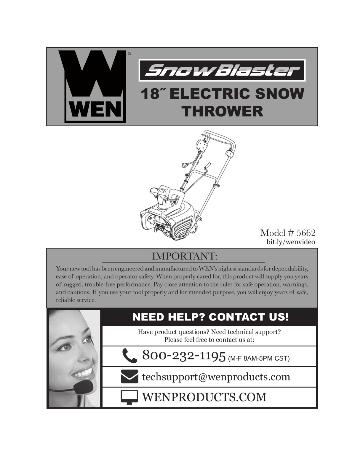
#5662!SNOW!THROWER!OPERATOR’S!MANUAL! 5!
!
Personal Safety
Stay alert, watch what you are doing and use common sense when operating your Snow Thrower.
Do not use your Snow Thrower while you are tired or under the influence of drugs, alcohol,
ormedication. A moment of inattention while operating the Snow Thrower may result in
seriousbodily injury.
NEVER LEAVE YOUR RUNNING SNOW THROWER UNATTENDED. Turn the power
switch toOFF. Do not leave your Snow Thrower until it has come to a complete stop.
Remove any adjusting key or wrench before turning the Snow Thrower on. A wrench or a key
thatis left attached to a rotating part of the Snow Thrower may result in bodily injury.
DO NOT OVERREACH. Keep proper footing and balance at all times. This enables better
controlof the Snow Thrower in unexpected situations. Hold the handles firmly to avoid injury.
When stepping backwards, be cautious about any obstacles beneath your feet or behind you
toavoid falling.
Snow thrower Use and Care
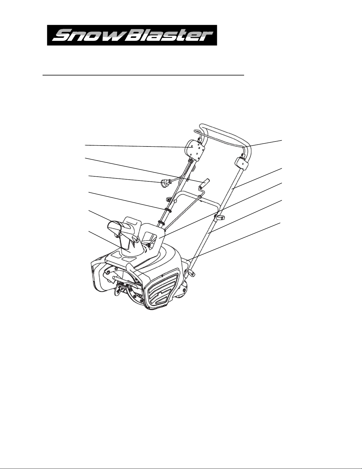
Know your snow thrower - Familiarize yourself with the main parts of your snow thrower.
Read the operator’s manual carefully. Learn your snow thrower’s applications and limitations
aswell as the specific potential hazards related to this machine. Do not use this machine for
anypurpose other than the one for which it was designed. Otherwise, it may cause
mechanicaldefaults, serious damage or personal injury.
Preliminary unit inspection - Thoroughly inspect the unit before use. Make sure all the parts
aresecure and installed correctly. If you notice any abnormalities, do not use the machine until it
hasbeen properly repaired. Always perform a test run the first time you use the snow thrower or
afterreplacing parts to ensure that the unit is functioning properly.
Preliminary area inspection - Clear the area to be plowed before each use. Remove all
objectssuch as rocks, broken glass, nails, wire, or string, which can be thrown by or become
entangled inthe snow thrower. Keep the area of operation clear of other people and pets.
Excessive force - The snow thrower was designed to respond at a certain rate for various
snowconditions for optimum safety and performance. Do not force it; keep pressure constant.
Malfunctioning switch - Do not use the snow thrower if the switch does not turn it on and off.
Anyelectrical appliance that cannot be controlled by the switch is not safe to use and must be
repaired.
Hitting an object - If the snow thrower accidentally strikes an object, stop the snow thrower;
inspectfor damage; repair or replace any damaged part before restarting and operating the snow
thrower.
Discharge chute safety - Never direct the snow discharge chute at the operator, at bystanders,
atvehicles or at windows. Thrown snow and foreign objects accidentally picked up by the
snowthrower can cause serious damage and personal injury. Do not use your hands to unclog
thedischarge chute. Stop the motor before removing debris.

!
#5662!SNOW!THROWER!OPERATOR’S!MANUAL! 6!
!
Abnormal operation - If you notice the snow thrower running in an unstable state or hear
abnormalsounds from the motor, stop the machine, disconnect the power immediately, and
contact our customer service department.
Noise control - When using the snow thrower, you must respect local laws and
regulationsregarding noise control and environmental protection. To avoid noise disturbance,
you shouldcarefully decide upon an appropriate operation time and consider the surrounding
conditions.
Disconnect the snow thrower from the power source when the machine is not in use, when
changing accessories, or before performing any maintenance.
Store safely - Store snow thrower indoors in a dry area between uses. Keep in a locked
areawhere children and unauthorized users cannot gain access. Do not store the machine while it
isstill connected to the power source. It may cause damage and injury.
Maintain for safety and longevity - Check for misalignment or binding of moving parts,
breakage ofparts, and any other conditions that may affect the unit’s operation. If damaged,
repair or replacethe damaged part before use. Use only those replacement parts made for your
model. Whenreplacing any parts, you must strictly observe the instructions and procedures
described in thismanual. Special care should be paid to any rubber parts, since these parts may
increase theengine load and decrease its mechanical power if damaged.
Symbols
These symbols represent important information about the product or instructions on its use.
WARNING:The following warning symbol is to remind you of the safety precautions
youshould take when operating the Snow Thrower.
Keep hands away from the moving parts of the Snow Thrower. The rotating parts
couldcause bodily injury.

!
#5662!SNOW!THROWER!OPERATOR’S!MANUAL! 7!
!
KNOW YOUR SNOW THROWER’S COMPONTENTS
1
LOWER FRAME
7
UPPER CHUTE CRANK
2
MIDDLE FRAME
8
POLARIZED PLUG
3
CARRYING HANDLE
9
CABLE CLIP
4
UPPER FRAME
10
CHUTE DEFLECTOR
5
HANDLE BAR
11
CHUTE
6
SWITCH
1!
2!
3!
4!
5!
6!
7!
8!
9!
10!
11!

!
#5662!SNOW!THROWER!OPERATOR’S!MANUAL! 8!
!
ASSEMBLY INSTRUCTIONS
Unpacking
1. Carefully remove your Snow Thrower and all other
items from box.
2. Your Snow Thrower comes with the following
accessories.
•T-bolt: 4 pieces
•Saddle Washer: 4 pieces
•Knob: 4 pieces
•Cable Clip: 3 pieces
•Upper Chute Crank: 1 piece
Middle Frame Assembly
For easier assembly, the handle frames are marked with yellow
tape from the factory. This tape indicates the LEFT side of each
handle’s part, as viewed from the operator’s position of the
Snow Thrower.
Hold the middle frame with the yellow tape on the LEFT side so
that the screw holes align with the holes on the lower frame.
Note also that the hole and grommet of the eyebolt at the top of
the middle frame are facing UP. (Fig. 1)
Insert a T-bolt into each hole with the head on the inside of the
handle. Then attach a saddle washer and knob on the outside
and tighten. (Fig. 2)
Repeat this step on the other side of the handle.
The bolts should be inserted from the inside of the frame of the
unit so that the washers and knobs are fastened to the outside of
the frame.
Note: Do not over-tighten the knobs.

!
#5662!SNOW!THROWER!OPERATOR’S!MANUAL! 9!
!
Upper Frame Assembly
For easier assembly, the handle frames are marked with yellow
tape from the factory. This tape indicates the LEFT side of
each handles part, as viewed from the operator’s position of the
Snow Thrower.
Hold the upper frame with the yellow tape on the LEFT side so
that the screw holes align with the holes on the middle frame.
(Fig. 3)
Insert a T-bolt into each hole with the head on the inside of the
handle. Then attach a saddle washer and knob on the outside
and tighten. (Fig. 4)
Repeat this step on the other side of the handle.
Locate the three Cable Clips in the parts bag. Secure the power
cord to the frame of the unit by clipping them onto the frame at
evenly spaced intervals. (Fig. 5)

!
#5662!SNOW!THROWER!OPERATOR’S!MANUAL! 10!
!
Discharge Chute Assembly (Fig. 6)
Lift the chute deflector so that it snaps and locks securely
onto the discharge chute.
Raise or lower the chute deflector to the desired height of the
snow stream and tighten the chute deflector knobs.
Note: Do not over tighten the chute deflector knobs.
Lower and Upper Chute Crank Assembly (Fig. 7)
Locate the upper chute crank in the parts bag. Loosen
thescrew and nut located on the lower chute crank with
screwdriver and wrench.
Note: You may be able to unfasten the screw and nut by
hand.
Slide the upper chute into the lower chute crank, aligning the
screw holes. Tighten the screw into the aligning holes usinga
screwdriver.
Tighten the nut with a wrench.
Note: If the center hole is not lining up correctly, youhave the middle frame on backwards.
The hole and grommet of the eyebolt should face up.

!
#5662!SNOW!THROWER!OPERATOR’S!MANUAL! 11!
!
OPERATION
KEEP CHILDREN AND BYSTANDERS AT A SAFE DISTANCE while operating your Snow
Thrower.
Note: Before using the Snow Thrower, please make sure the power source you will use is in
accordancewith the specifications shown in this manual.
Securing the Extension Cord
For safe and efficient use of your Snow Thrower, use only a UL-rated or CSA extension cord
recommendedfor outdoor use (see page 4).
To prevent the extension cord from disconnectingduring use,
tie the female end of the extension cordinto a loose knot on the
top right side of the middleframe before connecting to the male
plug in theswitch-housing socket of the snow thrower.
Note that the snow thrower has a polarized male plug with one
prong slightly longer and wider than the otherin the switch-
housing socket. The extensioncord female end should be
similarly polarized so the extension cord fits snugly into the
switch-housingsocket.

!
#5662!SNOW!THROWER!OPERATOR’S!MANUAL! 12!
!
Powering On and Off
To power on, first press and hold the switch button found
alongside the switch housing.
Pull the handle bar toward you and grasp hold ofit firmly with
both hands to start the machine. Themachine can only be started
by pressing the switchbutton before squeezing the handle bar.
When the motor is on, release the switch button, and keep hold
the handle bar.
Note:Reverse operation cannot start the machine.
To power off, release your grip on the handle bar.

!
#5662!SNOW!THROWER!OPERATOR’S!MANUAL! 13!
!
PLOWING THE SNOW
WARNING: Keep the area of operation free of foreign objects that can become thrown
bythe rotor blades. Perform a thorough inspection of the area since some objects may
behidden from view by surrounding snow. If the Snow Thrower hits an obstruction or
picks upa foreign object during use, stop the Snow Thrower, disconnect the extension cord,
removethe obstruction, and inspect the unit for damage. Repair or replace any damaged
partsbefore restarting and operating the unit.
Keep children, pets, and bystanders away from the area of operation. Be aware that the normal
noise of the Snow Thrower when turned on may make it difficult for you to hear approaching
people.
When moving the Snow Thrower, use the wheels on one side as the pivot point. Slightly tilt
theSnow Thrower on this pivot point to move it forward or backward.
Start your clearing path near the electrical outlet and work outward, throwing snow in a back
andforth motion. To clear in the opposite direction, step over the cord and pivot the Snow
Thrower on itswheels. Make sure to overlap clearing paths.
Note the wind direction. If possible, move in the same direction as the wind so that the snow is
notthrown against the wind, back into your face or onto the recently cleared path.
While moving the Snow Thrower, move within a range the cable can reach.
DO NOT USE HANDS TO UNCLOG CHUTE. Stop motor before removing debris.
Do not walk in front of a running Snow Thrower. Do not direct discharged snow
towardsbystanders.
Do not push the Snow Thrower with excessive force. You should push the Snow Thrower
gentlyand evenly in accordance with the unit’s throw rate.
Only use your Snow Thrower with the intention of moving snow. Other materials may hurt the
machine and endanger users and bystanders.
Some parts of the Snow Thrower may freeze under extreme temperature conditions. Do not
attemptto operate the Snow Thrower with frozen parts. If the parts freeze while the Snow
Thrower is in use,stop the Snow Thrower, unplug the extension cord, and inspect it for frozen
parts. Thaw all partsbefore restarting and operating the Snow Thrower. Never force parts or
controls that have frozen.Never use an open flame of any sort to thaw frozen parts.
WORKING ON PEBBLES, GRAVEL, OR UNPAVED SURFACES: To avoid throwing
loose surfacematerial along with the snow, push down on the handle to raise the scraper at the
base of the unitabove the pebbles or gravel.

!
#5662!SNOW!THROWER!OPERATOR’S!MANUAL! 14!
!
CHANGING SNOW DISCHARGE CHUTE’S DIRECTION
1. Never direct the snow discharge chute at the operator, bystanders, vehicles or nearby
windows.The discharged snow and foreign objects accidentally picked up by the Snow
Thrower can causeserious damage and bodily injury. Always point the discharge chute in the
opposite direction of anything you don’t want to hit with snow and foreign objects.
2. The discharge chute can be adjusted 180º by rotating the chute crank.Rotate the chute control
crank clockwise to move the discharge chute to the left and counterclockwiseto move the
chute to the right.
3. The chute deflector on the top of the discharge chute controls the height ofthe snow stream.
Loosen both chute deflector knobs to rise or lower the deflector tothe desired height of snow
you wish to throw. Tighten the knobs to secure the deflector.
Note: Do not over tighten the chute deflector knobs.
WARNING: Make sure that the chute deflector snaps and locks completely onto
thedischarge chute. An opening between the discharge chute and the chute deflectormay
allow foreign objects to be picked up by the Snow Thrower and thrown in thedirection
of the operator causing serious bodily injury. Do not advance the chutedeflector too far forward
to where an opening appears between the deflector anddischarge chute. Do not over tighten the
knobs on the chute deflector.

!
#5662!SNOW!THROWER!OPERATOR’S!MANUAL! 15!
!
MAINTENANCE
WARNING: Make sure to turn off the switch and disconnect the extension cord
beforeperforming any maintenance task on your Snow Thrower.
Snow Thrower Use and Care
1. KNOW YOUR LIMITATIONS. Do not overload your Snow Thrower’s capacity by
attempting to clearsnow at too fast of a rate.
2. Use of the Snow Thrower for operations outside of intended usages could result in a
dangerous situation.
3. Do not attempt to repair the Snow Thrower unless you have the proper tools and instructions
fordisassembly and repair.
4. Check the bolts at frequent intervals for proper tightness to ensure that the equipment is in a
safeworking condition.
5. After each snow removal session, run the Snow Thrower for a few minutes to prevent
thecollector/impeller from freezing. Shut off the motor, wait for all revolving parts to stop
completely,and wipe residual ice and snow off the unit. Rotate the chute crank several times
to remove anyexcess snow.
Lifetime Lubrication
Lubrication is not necessary and may damage the unit. The Snow Thrower is lubricated for
lifetimeuse at the factory before shipment.
STORAGE
1. Clean the Snow Thrower of snow and ice buildup before storing or transporting. Be sure to
securethe unit while transporting.
2. Disconnect the extension cord from the Snow Thrower.
3. Inspect the extension cord closely for signs of wear or damage. Replace it if it is worn or
damaged.
4. Inspect the Snow Thrower carefully for worn, loose, or damaged parts. Check connections
andscrews and tighten if necessary.
5. Store the unit, along with the disconnected extension cord, in a locked, dry place out of the
reach ofchildren to prevent unauthorized use or damage. Cover loosely with a tarp for added
protection.

!
#5662!SNOW!THROWER!OPERATOR’S!MANUAL! 16!
!
EXPLODED VIEW

!
#5662!SNOW!THROWER!OPERATOR’S!MANUAL! 17!
!

!
#5662!SNOW!THROWER!OPERATOR’S!MANUAL! 18!
!
PARTS LIST
Part#
Stock#
Description
Part#
Stock#
Description
1
56663-001
Locknut M6
46
56663-046
Small Gear
2
56663-002
Washer 6
47
56663-047
Flat Key 3x12
3
56663-003
Right Fixing Plate
48
56663-048
Bearing 608-2Z
4
56663-004
TPU/Rubber Plate
49
56663-049
Gear Box
5
56663-005
Washer 6
50
56663-050
Bearing 6001-2Z
6
56663-006
Screw M6x16
51
56663-051
Screw ST4.2-65
7
56663-007
Left Fixing Plate
52
56663-052
Lower Motor Housing
8
56663-008
Screw M6x16
53
56663-053
Impeller
9
56663-009
Bearing 6202-2Z
54
56663-054
Stator
10
56663-010
Keep Plate
55
56663-055
Rotor
11
56663-011
Shaft Assembly
56
56663-056
Upper Motor Housing
12
56663-012
Small TPU/Rubber Plate
57
56663-057
Brush Holder
13
56663-013
Screw ST4.2x13
58
56663-058
Carbon Brush
14
56663-014
Right Cover
59
56663-059
Keep Plate
15
56663-015
Screw M5x12
60
56663-060
Screw ST3.2x9.5
16
56663-016
Snap Ring 15
61
56663-061
Shock Pad
17
56663-017
Bearing Housing
62
56663-062
Motor Keeper
18
56663-018
Right Collision Strip
63
56663-063
Screw ST4.2x16
19
56663-019
Main Housing
64
56663-064
Idler Arm Assembly
20
56663-020
Tapping Screw ST4.2x22
65
56663-065
Extension Spring
21
56663-021
Scraper
66
56663-066
Washer 4
22
56663-022
Left Collision Strip
67
56663-067
Screw M4x12
23
56663-023
Big Pulley
68
56663-068
Flat Idler
24
56663-024
Belt PJ670
69
56663-069
Bearing 6000-2Z
25
56663-025
Locknut M8
70
56663-070
Washer 5
26
56663-026
Left Cover
71
56663-071
Fixing Seat
27
56663-027
Screw M6x30
72
56663-072
Main Cover
28
56663-028
Washer 10
73
56663-073
Lever Keeper
29
56663-029
Right Metal Support
74
56663-074
Chute Direction Control Gear
30
56663-030
Spacer
75
56663-075
Resistance Washer
31
56663-031
Roller
76
56663-076
Chute
32
56663-032
Roller Shaft
77
56663-077
Handle
33
56663-033
Cotton Pin 2x20
78
56663-078
Knob
34
56663-034
Left Metal Support
79
56663-079
Screw M8x25
35
56663-035
Screw M4x16
80
56663-080
Chute Deflector
36
56663-036
Screw ST4.2x40
81
56663-081
Blade
37
56663-037
Small Pulley
82
56663-082
Screw ST4.2x9.5
38
56663-038
Bearing Housing
83
56663-083
Lever
39
56663-039
Bearing 6201-2Z
84
56663-084
Connector
40
56663-040
Output Shaft
85
56663-085
Shaft
41
56663-041
Semicircular Key
86
56663-086
Cotton Pin 2x14
42
56663-042
Big Gear
87
56663-087
Rivet 4x20
43
56663-043
Snap Ring 10
88
56663-088
Lower Chute Crank

!
#5662!SNOW!THROWER!OPERATOR’S!MANUAL! 19!
!
44
56663-044
Oil Seal
89
56663-089
Locknut M4
45
56663-045
Nut M8
90
56663-090
Screw M4x20
Part#
Stock#
Description
91
56663-091
Eye Bolt
92
56663-092
Rubber Ring
93
56663-093
Upper Chute Crank
94
56663-094
Snap Ring 8
95
56663-095
Handle Grip
96
56663-096
Upper Frame
97
56663-097
Saddle Washer
98
56663-098
Middle Frame
99
56663-099
T-bolt
100
56663-100
Cable Clip
101
56663-101
Lower Frame
102
56663-102
Screw ST6.3x38
103
56663-103
Cable Jacket 7P-2
104
56663-104
Power Cord
105
56663-105
Big Cable Keeper
106
56663-106
Circuit Breaker
107
56663-107
Switch
108
56663-108
Switch Housing L
109
56663-109
Starter Button
110
56663-110
Spring
111
56663-111
Small Cable Keeper
112
56663-112
Switch Housing R
113
56663-113
Screw ST4.2x25
114
56663-114
Switch Seat R
115
56663-115
Switch Seat L
116
56663-116
Switch Actuator
117
56663-117
Spring
118
56663-118
Handle Bar

!
#5662!SNOW!THROWER!OPERATOR’S!MANUAL! 20!
!
ONE (1) YEAR LIMITED WARRANTY
SNOW BLASTER™ is committed to building tools that are dependable for years. Our warranties are consistentwith
our commitment and dedication to quality.
ONE (1) YEAR LIMITED WARRANTY OF SNOW BLASTER™ PRODUCTS FOR HOME USE.
GREAT LAKES TECHNOLOGIES, LLC (“Seller") warrants to the original purchaser only, that allSNOW
BLASTER™ consumer power tools will be free from defects in material or workmanship for aperiod of one (1) year
from date of purchase. Ninety (90) days for all SNOW BLASTER™ products, if thetool is used for professional use.
SELLER’S SOLE OBLIGATION AND YOUR EXCLUSIVE REMEDY under this One (1) Year Limited Warranty
and, to the extent permitted by law, any warranty or condition implied by law, shall be the repairor replacement of
parts, without charge, which are defective in material or workmanship and which have not been misused, carelessly
handled, or misrepaired by persons other than Seller or AuthorizedService Center.
To make a claim under this Limited Warranty, you must make sure to keep a copy of your proof of purchase that clearly defines
the Date of Purchase (month and year) and the Place of Purchase. Place of purchase must be a direct vendor of Great Lakes
Technologies, LLC. Third party vendors such as garage sales, pawn shops, resale shops, or any other secondhand merchant void
the warranty included with this product. Contact[email protected] or 1-800-232-1195 to make arrangements for
repairs and transportation.
When returning a product for warranty service, the shipping charges must be prepaid by the purchaser. The product must be
shipped in its original container (or an equivalent), properly packed to withstand the hazards of shipment. The product must be
fully insured with a copy of the warranty card and/or the proof of purchase enclosed. There must also be a description of the
problem in order to help our repairs department diagnose and fix the issue. Repairs will be made and the product will be returned
and shipped back to the purchaser at no charge.
THIS LIMITED WARRANTY DOES NOT APPLY TO ACCESSORY ITEMS THAT WEAR OUT FROM REGULAR
USAGE OVER TIME INCLUDING BELTS, BRUSHES, BLADES, ETC.
ANY IMPLIED WARRANTIES SHALL BE LIMITED IN DURATION TO ONE (1) YEAR FROM DATE
OFPURCHASE. SOME STATES IN THE U.S. AND SOME CANADIAN PROVINCES DO NOT
ALLOWLIMITATIONS ON HOW LONG AN IMPLIED WARRANTY LASTS, SO THE ABOVE LIMITATION
MAYNOT APPLY TO YOU.IN NO EVENT SHALL SELLER BE LIABLE FOR ANY INCIDENTAL OR
CONSEQUENTIAL DAMAGES(INCLUDING BUT NOT LIMITED TO LIABILITY FOR LOSS OF PROFITS)
ARISING FROM THESALE OR USE OF THIS PRODUCT. SOME STATES IN THE U.S. AND SOME
CANADIAN PROVINCES
DO NOT ALLOW THE EXCLUSION OR LIMITATION OF INCIDENTAL OR CONSEQUENTIAL
DAMAGES, SO THE ABOVE LIMITATION OR EXCLUSION MAY NOT APPLY TO YOU.
THIS LIMITED WARRANTY GIVES YOU SPECIFIC LEGAL RIGHTS, AND YOU MAY ALSO HAVE
OTHER RIGHTS WHICH VARY FROM STATE TO STATE IN THE U.S., PROVINCE TO PROVINCEIN
CANADA AND FROM COUNTRY TO COUNTRY.THIS LIMITED WARRANTY APPLIES ONLY TO
PORTABLE ELECTRIC TOOLS, BENCH POWER
TOOLS, OUTDOOR POWER EQUIPMENT AND PNEUMATIC TOOLS SOLD WITHIN THE
UNITEDSTATES OF AMERICA, CANADA AND THE COMMONWEALTH OF PUERTO RICO. FOR
WARRANTYCOVERAGE WITHIN OTHER COUNTRIES, CONTACT SNOW BLASTER™ CUSTOMER
SUPPORT.
Other manuals for 5662
3
Table of contents
Other Wen Snow Blower manuals