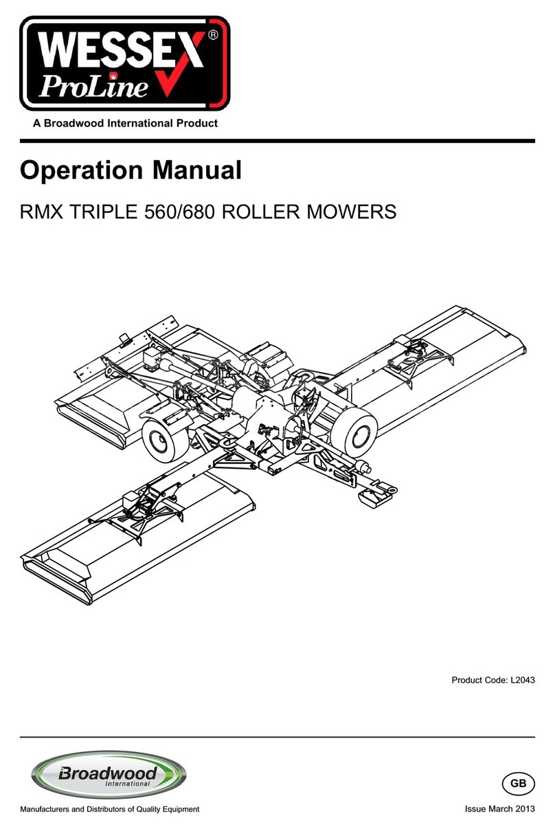
Wessex CRX-320 User manual

Operation Manual and Parts Book
Wessex CRX-320 Tri-Deck Roller Mowers
Product Code: L2064
Issue March 2019
GB


CONTENTS
Welcome to your new Wessex Product . . . . . . . . . . . . . . . . . . . . . . . . . . . . . . . . . . . . . . . . .3
Safety Decals . . . . . . . . . . . . . . . . . . . . . . . . . . . . . . . . . . . . . . . . . . . . . . . . . . . . . . . . . . .4, 5
Important Safety Warnings . . . . . . . . . . . . . . . . . . . . . . . . . . . . . . . . . . . . . . . . . . . . . . . . . . .6
Warranty . . . . . . . . . . . . . . . . . . . . . . . . . . . . . . . . . . . . . . . . . . . . . . . . . . . . . . . . . . . . . . . . .7
Linking up to the Tractor . . . . . . . . . . . . . . . . . . . . . . . . . . . . . . . . . . . . . . . . . . . . . . . . . . . .8
Using the Mower . . . . . . . . . . . . . . . . . . . . . . . . . . . . . . . . . . . . . . . . . . . . . . . . . . . . . . . . . . .8
Altering the Cutting Height / Belt Adjustment . . . . . . . . . . . . . . . . . . . . . . . . . . . . . . . . . . . . .9
Maintenance / Lubrication . . . . . . . . . . . . . . . . . . . . . . . . . . . . . . . . . . . . . . . . . . . . . . . . . . .10
Troubleshooting / Winter Storage . . . . . . . . . . . . . . . . . . . . . . . . . . . . . . . . . . . . . . . . . . . . .11
Cutting Blades / Specifications . . . . . . . . . . . . . . . . . . . . . . . . . . . . . . . . . . . . . . . . . . . . . . .12
CRX Trideck Hitch Guide . . . . . . . . . . . . . . . . . . . . . . . . . . . . . . . . . . . . . . . . . . . . . . . . . . .13
PTO Shaft - Operation and Maintenance . . . . . . . . . . . . . . . . . . . . . . . . . . . . . . . . . . . .14, 15
Parts Illustration and Parts List - CRX120 Drive Assembly . . . . . . . . . . . . . . . . . . . . . . . . .16
Parts Illustration and Parts List - CRX 120 Rollers . . . . . . . . . . . . . . . . . . . . . . . . . . . . . . . .17
Parts Illustration - Spindle and Blade Assembly . . . . . . . . . . . . . . . . . . . . . . . . . . . . . . . . . .18
Parts List - Spindle and Blade Assembly . . . . . . . . . . . . . . . . . . . . . . . . . . . . . . . . . . . . . . .19
Parts Illustration - Mainframe . . . . . . . . . . . . . . . . . . . . . . . . . . . . . . . . . . . . . . . . . . . . .20, 21
Parts List - Mainframe . . . . . . . . . . . . . . . . . . . . . . . . . . . . . . . . . . . . . . . . . . . . . . . . . . .22, 23
Parts Illustration - Wing Frame Assembly . . . . . . . . . . . . . . . . . . . . . . . . . . . . . . . . . . . . . . .24
Parts List - Wing Frame Assembly . . . . . . . . . . . . . . . . . . . . . . . . . . . . . . . . . . . . . . . . . . . .25
Parts Illustration - Rear Chassis . . . . . . . . . . . . . . . . . . . . . . . . . . . . . . . . . . . . . . . . . . . . . .26
Parts List - Rear Chassis . . . . . . . . . . . . . . . . . . . . . . . . . . . . . . . . . . . . . . . . . . . . . . . . . . .27
Parts Illustration and Parts List - Centre Latch Assembly . . . . . . . . . . . . . . . . . . . . . . . . . . .28
Parts Illustration and Parts List - Rear Latch Assembly . . . . . . . . . . . . . . . . . . . . . . . . . . . .29
Parts Illustration - CRX Central Gearbox . . . . . . . . . . . . . . . . . . . . . . . . . . . . . . . . . . . . . . .30
Parts List - CRX Central Gearbox . . . . . . . . . . . . . . . . . . . . . . . . . . . . . . . . . . . . . . . . . . . . .31
Safety Training Induction . . . . . . . . . . . . . . . . . . . . . . . . . . . . . . . . . . . . . . . . . . . . . . . . . . . .32
Daily Inspection Record . . . . . . . . . . . . . . . . . . . . . . . . . . . . . . . . . . . . . . . . . . . . . . . . . . . .33
Notes . . . . . . . . . . . . . . . . . . . . . . . . . . . . . . . . . . . . . . . . . . . . . . . . . . . . . . . . . . . . . . . . . . .34
CE Certificate . . . . . . . . . . . . . . . . . . . . . . . . . . . . . . . . . . . . . . . . . . . . . . . . . . . . . . . . . . . .35
1


3
WELCOME TO YOUR NEW WESSEX PRODUCT
Thank you for purchasing a Wessex product. As a Wessex customer, you now number among the
most important people of our business and we will endeavour to give you the best service available
through our dealer network.
Please read this Manual carefully and familiarise yourself and other persons that will be using the
machine with its contents, to ensure the optimum performance and working life of your machine. It
is advisable that a copy of this Manual is kept in the workshop and one copy with the machine.
Further copies are available through your dealer.
On delivery, your dealer should go through the workings of the machine with you, explaining the
setting up procedures, all of which are contained in this manual for further reference. The Warranty
Registration Form must also be completed and returned to us within 7 days of delivery in order
to validate the Warranty.
PLEASE READ THE FOLLOWING PAGES CAREFULLYBEFORE USING YOUR MACHINE
AND KEEP THIS MANUAL IN ASAFE PLACE.
THIS SAFETY SYMBOL IS TO ALERT OPERATORS OF AHAZARD
THAT MAYRESULT IN INJURY.
ALWAYS FOLLOW INSTRUCTIONS CAREFULLY

4
SAFETY DECALS
GB ATTENTION Description of pictograms.
FATTENTION Description des pictogrames.
DVORSICH Beschreigung der piktogramme.
GB Read Operating manual before use.
FLisez Manual D’Opéreration avant l’utilisation.
D Vor der Benutzung, Betriebshandbuch lesen.
GB Ear defenders must be worn.
FDéfenseurs des oreilles doivent être portés.
DGehörschutz getragen werden.
GB Never remove guards or attempt adjustment until rotor has stopped.
FNe retirez jamais les gardes ou d'ajustement tentative jusqu'à ce que toutes les pièces mobiles ont
été interrompus.
DSchutzvorrichtung niemals abnehmen oder einstellung versuchen, bevore der rotor abstellt.
GB Bystanders must be at least 20 metres from machine range of action.
FDes spectateurs doivent s’écarter au moins 20 mètres du rayon d’action de la machine.
DUmstenhenden müßen sich mindestens 20 meter vom maschinenbetriebsraum entfernen.
GB Stand clear. Flying objects possible.
FS’écartez! Possibilité d’objets volants.
DZurückbleiben! Herumfliegende objekte möglich
GB Examine blades regularly. The operator is responsible for machine damage caused by unbalanced
rotors.
FExaminez des lames régulièrement. L’opérateur est responsable des dommages à la machine
provoqés par des rotors mal equilibrés
DKlingen regelmäßig kontrollieren. Der abeiter ist an den durch unausgewogenen rotoren
maschinenschäden verantwortlich.
GB Keep hands and feet clear
FGarder les mains et les pieds.
DHalten Sie Ihre Hände und Füße.
GB Grease points
FLes points de graissage
DGrease Punkte.
VIBRATION
GB Liftt Machine before turning
FLevez la machine avant de la tourner
DMaschine aufheben, bevor man sie umdreht.

5
SAFETY DECALS
GB Lifting Point
FPoint de levage
DAnschlagpunkt
IMPORTANT NOTICE
FITTING PTO SHAFT TO MACHINE & TRACTOR
nAll safety chains must be anchored tight enough to allow a small amount of movement, but not
enough to wrap around the P.T.O. Shaft.
nEnsure that the shafts and guards are regulary greased to avoid overheating and to give
lubrication.
nImportant: Thoroughly read through the P.T.O. manufacturers instruction book provided with
the CRX before using the P.T.O. Shaft.
P.T.O. Shafts are not covered by the Wessex Warranty.
GB Safety Chains must be anchored tightly. Never allow chains to wrap round PTOshaft. Grease PTO
shaft regularly.
FChaînes de sécurité doit être ancré solidement. Ne laissez jamais les chaînes à entourer le
transmission. Régulièrement graisse le transmission.
DSicherheitsketten müssen fest verankert sein. Lassen Sie niemals Ketten zu runden Zapfwelle zu
wickeln. Fett Gelenkwelle regelmäßig.
GB CORRECT BELTTENSION: Check belt tension regulary:
10mm of belt deflection at thumb pressure between pulleys.
FTENSIONNEMENT CORRECT DE LA COURROIE : Contrôler le tensionnement régulièrement :
la déflexion de la courroie sous la pression du pouce entre les deux poulies doit être de 10 mm.
DKORREKTE RIEMENSPANNUNG: Riemenspannung regelmäßig überprüfen:
10 mm Eindrücktiefe bei Daumenduck zwischen Riemenscheiben.
10 mm
GB When machine is operating with the wings down, please ensure that the tractors hydraulic
spool valve is in the float position.
FLorsque la machine est en marche avec les ailes vers le bas, s'il vous plaît assurer que le dis-
tributeur à tiroir hydraulique des tracteurs est en position flottante.
D Wenn die Maschine mit Flügeln nach unten läuft, stellen Sie bitte sicher, dass der
Schlepperhydraulik Schieberventil in der Schwimmstellung ist.
10SECS
GB Disengage the PTO drive and wait for 10 seconds before lifting wings into their
latched position.
FDésengager la prise de force et attendre 10 secondes avant de soulever les ailes
dans leur position de verrouillage.
DLösen Sie den Zapfwellenantrieb und 10 Sekunden warten, bevor Flügel in ihre
Verriegelungsposition anheben.

6
IMPORTANT SAFETY WARNINGS
Wessex machines are guarded for your protection, but you must always observe certain
elementary precautions. Machines are potentially dangerous and should be used with the greatest
respect and ALL OPERATORS MUST read this manual and be are aware of all safety
precautions.
1. NEVER attempt any adjustment whatsoever, unless the machine is COMPLETELYat a
standstill and the P.T.O. drive and blades have stopped turning. Stop Engine and remove
Tractor Key.
2. NEVER attempt to clear any obstructions around the mower unless the machine is
COMPLETELYat a standstill and the P.T.O. drive and blades have been stopped. Stop
Engine and remove Tractor Key.
3. NEVER remove belt guards unless the machine is COMPLETELYat a standstill. Stop
Engine and remove Tractor Key.
4. NEVER remove safety guards which are provided for your protection.
5. NEVER operate the mower with people around, keep everybody (especially children and
animals) at a safe distance, minimum 20 metres.
6. Stand well back from the machine when cutters are spinning.
7. Regularly inspect the BLADES AND FIXING BOLTS to ensure that they are in excellent
condition. Replace blades IMMEDIATELYif any signs of fracture or excess wear becomes
apparent. Serious damage, which is excluded from our warranty conditions, may result from
using your mower with an unbalanced rotor. When replacing blades, always fit new
mounting bolts and nuts to ensure that the rotor is balanced and running smoothly.
HEALTH AND SAFETY - Noise at Work Regulations
READING AT THE OPERATORS EAR
Wessex CRX Roller mower: Approximately 95 D.B.A
Depending on conditions, powering tractor and material being cut, this reading may alter, it is
therefore advisable for users to do their own assessment.
In compliance with the above regulations, Ear Protectors must be worn when
operating this machinery.

7
WARRANTY
Your Wessex product or equipment is warranted free from defect in workmanship or manufacture
for one year from date of purchase. Any parts which appear to us to be defective, either in material
or workmanship shall be replaced or repaired at no cost to the purchaser, subject to the following
conditions:
1. You should register your product within seven days of purchase via our Website:
www.wessexintl.com/warranty-registration
Alternatively if you prefer, please telephone Wessex International on +44 (0)1264 345888.
2. Any failure in the machine should be reported in the first instance immediately to your
dealer, who will act on your behalf to resolve the matter to your satisfaction.
3. The defective parts will be returned by your dealer to us, accompanied by a full statement
describing the failure and the circumstances and conditions in which the failure occurred.
4. The following are specifically excluded from our terms of warranty:
a) Fair wear and tear, especially to belts, blades, bearings and bushes.
b) Damage caused through incorrect adjustment (see instructions).
c) Damage caused by neglect or lack of lubrication.
d) Damage caused by misuse or abuse, including impact damage to blades.
e) Damage caused whilst the machine is in transit.
f) Damage caused to the frame of the machine by running the machine with
unbalanced rotors, blades or blade bars.
g) Damage caused to the machine by use with loose nuts, bolts, screws or any other type
of fittings.
h) Please note that P.T.O. Shafts are not covered by the Wessex warranty.
i) Damage caused to the machine by impact or collision to the machine . Howsoever
caused.
5. The warranty is for the benefit of the first user only.
6. Wessex International decisions will be final and binding.
Note:
It is recommended that every machine is inspected after one hour of operation to check that
all nuts, bolts, screws or any other types of fixings are tight and any loose fixings or
components should be rectified as appropriate.
Further inspections should be carried out at regular intervals thereafter.

8
LINKING UP TO THE TRACTOR
1. Always hitch and unhitch on level ground for safety reasons.
2. When hitching up, never allow anyone to stand between the tractor and the implement.
3. Reverse the tractor up to the CRX Tri-deck and hitch up to the towing hitch. When using a
drawbar pin ensure that it is secured with a lynch pin.
4. When in work the drawbar of the CRX Tri-deck should be level with the ground, to adjust simply
remove drawbar holding bolts and turn the drawbar over for extra hight adjustment.
5. Stop the tractor’s engine and couple the P.T.O. shaft to the tractor putting the wide angle joint
onto the tractor. Always hook the P.T.O. chains onto the lugs provided and shorten the chains to
suit if required. The P.T.O. chains must not encircle the P.T.O. guard, as this will cause
premature P.T.O. guard damage and wear. Ensure that the P.T.O. Shaft is correctly located and
locked in place. (See P.T.O. shaft Instructions at the back of this manual).
6. If so equipped, connect the lighting plug into the tractor.
7. Connect the hydraulic hoses to the tractor. The CRX Tri Deck hydraulics are double acting and
of the two hoses provided, one should be connected to the flow port of the double acting tractor
spool and the other to the return port.
8. IMPORTANT:Ensure that the bottom link arms of the tractor do not come into contact the the
P.T.O. Shaft when turning. We recommend that you remove or raise up the tractor link arms by
adjustment of the arms.
9. For drawbar use the CRX Tri-deck can be equipped with a screw jack. To avoid damage to the
jack, remove and stow before moving or operating the mowing decks.
USING THE CRX TRI-DECK
1. Having hitched up to the tractor you are now ready to lower the mowing decks to the ground.
2. Important Ensure that all bystanders are at a safe distance from the machine and that the
machine is located on level ground before lowering the decks.
3. Operate the hydraulic spool function to take the weight off the safety catches of the side and
rear deck carriers.
4. Release the safety catches by activating the catch lever beside the drawbar at the front of the
machine, then slowly activate the hydraulic spool to lower the decks to the ground. Continue
to actuate the spool lever in lowering position for three seconds after the decks contact the
ground to ensure that the lift rams are fully extended. This will allow the cutting decks to follow
the ground contours fully. While mowing, the spool level should then be placed in the neutral
position.
5. When safe to do so, slowly engage the P.T.O. drive and select the forward speed carefully.
Start off slowly until you are confident with the working width and capability of the machine.
6. NEVER USE THE MOWER WITH P.T.O. SPEEDS IN EXCESS OF 540 RPM.
7. When mowing longer thicker grass a slower forward speed will need to be selected.
8. When mowing the CRX Tri-deck is capable of following very undulating ground conditions and
with care the side arms will happily run up or down banks of up to 30 degrees.
9. When lifting the mowing decks up and out of work STOP THE P.T.O. drive before lifting.
SERIOUS DRIVE LINE DAMAGE WILL RESULT IF THIS ADVICE IS IGNORED.

9
BELT ADJUSTMENT
The drive belts are adjusted by moving the gearbox on its mounting bracket in relation to the
mower deck.
First, stop the tractor engine and remove the starting
key. Second, slacken the four holding bolts (A) on
the base of the gearbox-mounting bracket. To tighten
belts, turn the rear adjusting nut (B) anticlockwise,
and to slacken the belts, turn clockwise.
The belts should be free to move approximately
10 mm under finger pressure. If they are too tight,
there will be undue stress on the driven parts.
When belts are adjusted correctly, lock the adjusting
nut in place, and tighten the gearbox holding bolts.
Both drive belts should be tightened equally.
1. Loosen, but do not remove the fixing bolts (A). There are two on each side of the main deck.
2. Turn the adjusting screws (B) clockwise to lower the rollers, thus increasing the cutting height, or
anticlockwise to raise the rollers, thus reducing the height of cut. Ensure that all screws are
adjusted by the same amount otherwise the cut will be uneven. There is a triangular marker on
the adjuster to assist in checking for even adjustment.
3. Ensure all the height adjusters are equally set and then tighten all fixing bolts, (A).
ALTERING THE CUTTING HEIGHT (Rollers)
B
A
B
A

10
MAINTENANCE
To keep your CRX Tri-deck in excellent working condition we recommend that you follow this
maintenance programme:-
REGULARLY:-
=
Lubricate your CRX as indicated in this manual.
=
Check all drive belts for tension and replace if cut, frayed or worn.
=
Inspect all blades regularly and replace any that are badly worn, chipped or broken
which may cause an imbalance in the blade rotor assembly.
=
DO NOT RUN MACHINE WITH UNBALANCED BLADE ROTOR ASSEMBLIES, THIS
CAN CAUSE SERIOUS VIBRATION DAMAGE (NOT COVERED BY WARRANTY), TO
THE MACHINE.
=
Inspect front and rear rollers and their bearings.
=
Inspect for loose fixings and rectify immediately.
=
Regularly clean all debris from under the belt covers.
At the end of the grass cutting season always clean the CRX Tri-deck thoroughly and grease
before winter storage.
Only use genuine Wessex parts in the event of replacing worn parts. This will ensure the
continued safe use of your CRX Tri-deck and the validity of your warranty.
LUBRICATION
It is very important that the machine receives its recommended maintenance routine to ensure a
long trouble free working life and full validation of your warranty.
To ensure access to all grease points it is recommended that a grease gun with a flexible end
fitting is used.
DAILY:- (8 Hours)
=
Grease Roller bearings.
=
Inspect Blades, ensure all pairs are equal in condition to ensure the blade rotor assembly runs
without vibration.
WEEKLY:- (40 Hours)
=
Grease height adjustment points.
=
Grease Cutter Spindle bearings with Wessex XP High Performance grease.
=
Check Gearbox oil level.
=
Lubricate all adjusting threads.
=
Grease P.T.O. Shaft bearings.
=
Grease P.T.O. Tube slides.
=
Oil Wing release cables.

11
WINTER STORAGE
Before winter storage, the CRX Tri-deck should be thoroughly inspected:-
=
Repair or replace any worn or broken parts.
=
Check oil level in the gearbox. Top up or change with EP90 gear oil.
=
Take special care to look at the blades, rotor and the bearings.
=
Remove the belts and ensure that the rotors are free-spinning.
=
Make sure that the belts are in good condition before re-fitting.
=
Thoroughly wash the machine to remove all oil, grease, debris and materials.
=
Grease all grease points before storage to avoid any corrosion.
=
After pressure washing always run mower for a time to expel any water from bearings.
=
It is recommended to apply a light oil to the under-deck surfaces to protect the machine from
corrosion while in storage.
TROUBLESHOOTING
FAULTCAUSE REMEDY
Leaving wheel track uncut 1. Forward speed too fast
2. Cutting height too high
3. Excessive blade wear
Reduce forward speed
Lower cutting height
Replace blades
Bad quality of cut 1. Forward speed too fast
2. Excessive blade wear
3. Belts slipping
Reduce forward speed
Replace blades
Tighten belts
Narrow strip uncut 1. Possibly missing or broken
blade
Inspect blades and replace as
necessary
Excessive vibration 1. Damaged or missing blades
2. Main spindle bearing play
3. Loose part
Inspect and replace blades
Inspect bearing, replace if damaged
Check all nuts and bolts are tight
Excessive scalping 1. Cutting height too low Raise cutting height.

12
=
Inspect the Cutting blades regularly.
=
Badly worn or broken blades will unbalance rotors causing vibration.
=
Do not use with unbalanced rotors.
=
Always replace blades on both ends of bars to avoid imbalance.
=
Always lift machine and prop the machine up with axle stands. Never get underneath an
unsupported machine.
=
Replace blade tips using new nylock locking nuts every time.
SPECIFICATIONS
Wessex Proline CRX Multicut Mowers
Model: CRX-320
Cutting Width: 3.2m
Overall Width: 3.35m
Overall Length: 3.72m
Weight: 1360kg
Cutting Height Range (Rollers): 10-110mm
No. of Cutting Spindles: 9 (18 blades)
Gearbox Oil: EP90
CUTTING BLADES

13
CRX Trideck Hitch Guide
Standard drawbar hitch for compact tractor
double clevis towing jaw.
Part number:- WX-47080
Double clevis jaw for single clevis drawbar
use (USA) Two height adjustments.
Part number:- WX-49080
Ring hitch for tractor pick-up hitch.
Part number:- WX-47180
Ring hitch and removable nylon puck
for double clevis drawbar use.
Part numbers:- WX-47180 and WX-48780

14
IMPORTANT!
P.T.O. drive shafts must only be used for their intended purpose.
P.T.O. drive shafts are designed for specific machine types and power requirements.
They must not be replaced by other models.
Ensure that the P.T.O. drive shaft is securely connected.
Only use a completely protected drive system:
P.T.O. drive shaft with complete guard and complementary guard on tractor and
implement. Acomplete guard is essential in all working positions.
LUBRICATION
Lubricate with quality grease before starting work
and every 40 operating hours.
Ensure the P.T.O. guard bearings are lubricated, the end ball
shaped covers need retracting to expose all grease nipples.
Clean and grease the P.T.O. drive shaft before each
prolonged period of non-use.
Grease the guard tubes in winter to prevent freezing.
COUPLING THE P.T.O. SHAFT
Stop the tractor engine and remove the starting key.
Clean and grease the P.T.O. and PIN
Q.-d pin
Press q.-d. pin and simultaneously push P.T.O.
drive shaft onto P.T.O. until pin engages.
PTO SHAFT OPERATION AND MAINTENANCE

15
LENGTH ADJUSTMENT
To adjust the length, hold the half-shafts next to each other in the
shortest working position and mark them.
Shorten inner and outer guard tubes equally.
Shorten inner and outer sliding profiles by the same
length as the guard tubes.
Round off all sharp edges and remove burrs.
Grease sliding profiles.
No other changes may be made to the P.T.O. drive shaft
and guard.
CHAINS
Chains must be fitted so as to allow sufficient
articulation of the shaft in all working positions.
Do not let the chains encircle the P.T.O. guard in use as this will
shorten the life of the P.T.O. guard.
The PTO drive shaft must not be suspended from
the chains! Please use the P.T.O. Support Prop provided.
PTO SHAFT OPERATION AND MAINTENANCE

16
PARTS ILLUSTRATION - CRX120 DRIVE ASSEMBLY
1
2
8
9
5
10
11
12
13
14
15
16
17
18
19
20
22
22
21
23
24
21
20 20
3
4
25
5
6
7
PARTS LIST - CRX120 DRIVE ASSEMBLY
Item No. Part No. Description Qty.
1WX-21077 Left Hand Belt Guard 1
2WX-16503 Belt Guard Fastening Set 2
3WX-5257 Gearbox - Cutting Deck 1
4WX-8481 PTO Cover Adapter 1
5WX-4603 Gearbox Adjuster Plate Fastening Set 4
6WX-18877 Gearbox Plate Cover 1
7WX-16503 Gearbox Plate Cover Fastening Set 2
8WX-0801 Gearbox Fastening Set 1
9WX-27976 Gearbox Adjuster Plate 1
10 WX-1257 Belt Tension Adjuster 1
11 WX-21177 Right Hand Belt Guard 1
12 WX-16503 Belt Guard Fastening Set 2
13 WX-11770 Blade Bar Fastening Set 3
14 WX-1739 Blade Fastening Set 6
15 WX-11370 Blade Tip 6
16 WX-11670 Blade Bar 3
17 WX-5966B Spindle Assembly 3
18 WX-48980 Spacer for Taper Lock Pulley 3
19 WX-18166 Spacer for Non-Taper Lock Pulley 3
20 WX-13862 2 Row Pulley 3
21 WX-14062 Taper Lock 3
22 WX-6434 Deck Belt 2
23 WX-3962 Gearbox Pulley 1
24 WX-0547 Gearbox Pulley Key 1

17
PARTS ILLUSTRATION - CRX120 ROLLERS
3
5
4
11
7
8
8
9
10
1
2
4
6
5
PARTS LIST - CRX120 ROLLERS
Item No. Part No. Description Qty.
1WX-43676 CRX 120 - Adjustable Side Plate - Left Hand 1
2WX-21077 CRX120 - Left Hand Belt Guard 1
3WX-11355 CRX120 - Roller Assembly 2
4WX-0541 Bearing Unit 4
5WX-6501 Bearing Unit Fastening Set 4
6WX-43776 CRX120 - Adjustable Side Plate - Right Hand 1
7WX-1105 CRX Roller Adjustment Screw 4
8WX-9330 CRX120 - Roller Scraper Wire 2
9WX-16503 Belt Guard Fastening Set 2
10 WX-21177 CRX120 - Right Hand Belt Guard 1
11 WX-0246 Grease Nipple 4

18
PARTS ILLUSTRATION - SPINDLE & BLADE ASSEMBLY
1
18
2
3
4
5
15
9
10
6
4 → 8
14
7
8
11
12
13
16
17
19
Table of contents
Other Wessex Lawn Mower manuals

Wessex
Wessex TRMX TRIPLE 560 User manual

Wessex
Wessex AFE160 User manual

Wessex
Wessex AFE120 User manual

Wessex
Wessex WFM 125 User manual

Wessex
Wessex RMX Tri-Deck 560 User manual

Wessex
Wessex AF120 User manual

Wessex
Wessex AF160 User manual

Wessex
Wessex AT110 User manual

Wessex
Wessex CRX150 User manual

Wessex
Wessex AFR User manual