Westell Boxer BXB19-D User manual

Equipment Issue A
030-100689 Rev. A, September 2010
Section BXB-19D-20A
R
E2010 Westell, Inc. All rights reserved.
Westellris a registered trademark of and Boxertis a trademark of Westell, Inc. Page 1 of 21
1009IARA
WestellrBoxertBXB19-D Outdoor Battery Box
CONTENTS PAGE #
1. GENERAL 1. . . . . . . . . . . . . . . . . . . . . . . . . . . . . . . . . . . .
2. FEATURES 2. . . . . . . . . . . . . . . . . . . . . . . . . . . . . . . . . .
3. INSTALLATION 4. . . . . . . . . . . . . . . . . . . . . . . . . . . . . . .
4. MAINTENANCE 12. . . . . . . . . . . . . . . . . . . . . . . . . . . . .
5. CUSTOMER & TECHNICAL SERVICES 12. . . . . . . .
6. WARRANTY & RETURNS 12. . . . . . . . . . . . . . . . . . . . .
7. SPECIFICATIONS 13. . . . . . . . . . . . . . . . . . . . . . . . . . . .
8. APPENDIX A− Product Views 14. . . . . . . . . . . . . . . . . .
1. GENERAL
1.1 Document Purpose
This document provides general, installation, and specifica-
tion information for the WestellrBoxertBXB19-D Outdoor
Battery Box, which is shown in Figure 1. The intended audi-
ence for this document is Network engineering, operations,
and installation personnel. See Table 2 for ordering informa-
tion on this product and for available orderable options for this
product. Consult the documentation shipped with the two Box-
er cabinets that are typically installed above this battery box
(the 20-RU equipment cabinet and the side car cabinet) .
- NOTE -
Hereafter, the Westell Boxer BXB19-D Battery Box may be
referred to as the battery box" or the BXB19-D." The Boxer
cabinet installed above the battery compartment of the battery
box hereafter may be referred to as the equipment cabinet" or
the Boxer 20" and the Boxer customer-demarcation cabinet
installed above the cable access compartment of the battery box
may be referred to at the side car" cabinet.
1.2 Document Status
Whenever this practice is updated, the reason will be stated in
this paragraph.
1.3 Product Purpose and Description
The two-compartment Boxer battery box is designed to be
mounted with and under a Boxer 20-RU equipment cabinet and
a Boxer Side Car" cabinet (see Figure 2 for an assembled,
installed, but open view of the cabinets mounted on the battery
box).The battery box provides an enclosed, weather-resistant,
vented space for an optional battery back-up system for the
Boxer equipment cabinet. One of the two compartments of the
battery box is an enclosed aesthetically-concealed area for
cable access, storage, ingress and egress. The open ceiling of
this cable concealment compartment allows generous and am-
Figure 1. Isometric View of Boxer Battery Box
Figure 2. Boxer Cabinets Mounted on Battery Box
Cable Access
Compartment
of Battery Box
Side Car"
Boxer Cabinet
(demarcation)
Boxer 20-RU
Equipment
Cabinet
Battery
Compartment
of Battery Box
ple cable and conduit access and routing through the
compartment and into both Boxer cabinets mounted above it.
The other compartment is for customer-supplied batteries.
The battery compartment is vented. Both compartments have
a large, grounded, door panel which can be locked and un-
locked with a 216 tool or can wrench. The battery compartment
also contains a hasp on the front panel for an optional padlock.
A kit shipped with the battery box is located in the battery
compartment and contains the parts listed near the end of
Paragraph 1.5. See Table 2 for specific models and included
parts.

Section BXB-19D-20A 030-100689 Rev. A R
21009IARA
Figure 3. Isometric Open View of Boxer Battery Box
Cup
Washer
Screw
Removable door panel* for
cable access compartment
Battery
compartment
Removable door panel*
for battery compartment
Cup Washer
Screw
*Ground Braid Straps
for each door panel
not shown.
Optional battery
heater pad
Divider wall panel between
compartments
Cable
access
compartment
1.4 Product Mounting
The Boxer battery box is mounted with and under a Boxer
equipment cabinet (on the left side) and a side car cabinet (on
the right side). The conjoined Boxer system is typically
installed outdoors, above ground, on a concrete pad. All
mounting hardware and surfaces must be capable of support-
ing the weight of the entire 3-unit Boxer system plus the weight
of any equipment and batteries placed in them.
1.5 Product Features
The Boxer battery box is comprised of the following features
and capabilities.
SWeather-resistant battery box
SNEMA 3R
SPad mountable, and optional pad-mount kit
SNine top-surface holes facilitate attachment to the Boxer
cabinet mounted above it
SSecurity and access via 216 tool or can wrench
SOptional battery heater pad
SSize = 14" (H) x 34.5" (W) x 18.8" (D)
SWeight = less than 30 pounds
Battery Compartment
SLockable yet detachable access panel
SLouvered and screened side wall vents
SBraided ground cable (bonds panel to battery box)
SKit of parts, which contains the following items:
SMulti-connector battery cable assembly
S2 bond straps
SOne battery tie-down strap
SBag of hardware (includes screws, washers, and lock
nut(s) to attach the battery box to the cabinet)
Cable Access Compartment
SLockable yet detachable access panel
SOpen top surface and generous knock-outs in floor for
generous cable/conduit access
SBraided ground cable (bonds panel to battery box)
2. FEATURES
This section describes the exterior and interior features of the
WestellrBoxertbattery box in more detail. Refer to Figure 3
as needed while reading this section.
2.1 Construction and Materials
The Boxer battery box is designed to be weather-resistant for
above-ground applications. As such, the cabinet withstands cli-
matic conditions such as rain, snow, sleet, high winds, ice and
sand storms. To help meet these conditions, the exterior box
material is aluminum with powder-coated paint.

Section BXB-19D-20A
030-100689 Rev. A
R
3
1009IARA
2.2 Battery Compartment
When viewed from the front, the battery compartment is on the
left side of the battery box. This large compartment is pro-
tected by a padlockable door panel, and contains louvered and
screened side-wall vents for air circulation. On the inside walls
of the compartment are tie-down railings to secure the batter-
ies. Provided is a battery spacer block (shown in Figure 4)
which can be used to help insure a snug fit when smaller batter-
ies are used. The open top surface allows ample access to any
cable access holes in the cabinet installed above the battery
box.
2.2.1 Door Panel
The battery compartment is protected by a full-size removable
door panel which provides ample technician and equipment ac-
cess to the interior of the compartment. For security, at the top
of the panel are two cup-washer screws, which unlock with a 216
tool or can wrench. A padlock hasp offers additional security.
When closed and locked in position, a gasket on the inside pe-
rimeter of the door panel abuts or makes contact with the outer
perimeter of the compartment’s opening. When the hex cup-
washer screws (door lock) are tightened, the door panel and
gasket provide a seal to protect the batteries installed inside the
compartment.
2.2.2 Battery Tie-down Railings
On both the left and rear inside walls of the battery compart-
ment is a slotted, full-width, tie-down railing used to secure
batteries installed in the compartment. The provided tie-down
strap can be anchored to these railings then wrapped around
the batteries and tightened, to hold batteries in place.
2.2.3 Battery Spacer Block
The battery box is provided with a sturdy, rectangular, battery
spacer block that is designed to be used between the back wall
of the compartment and the rear of the installed batteries, to
help insure a snug and square fit of smaller batteries placed in
the compartment.
- COMPARTMENT DIVIDER WALL NOTE -
Between the left-side Battery Compartment and the right-side
Cable-Access Compartment is a secure but detachable divider
wall, to facilitate battery or cable installation, if needed.
2.3 Cable-Access Compartment
When viewed from the front, the cable-access compartment is
on the right side of the Boxer battery box.
2.3.1 L-Shaped Cable Access Panel
The cable-access compartment is secured and opened via a
large, vented, removable, L-shaped, locking access panel. This
panel, shown detached in Figure 3, is opened and locked using
a 216 tool or can wrench at the exterior cup-washer screw.
Figure 4. Top Isometric View of Battery Compartment
Tie-down railing
for batteries
Battery Spacer Block
(not used with deeper
batteries)
Hole for padlock hasp
Mounting hole (1 of 9) for
cabinet above battery box
Figure 5. Top Isometric View of Cable Compartment
1.8" Hole for
AC Conduit
1.5" Hole
Divider wall panel
between
compartments
Open
ceilings
Mounting hole (1 of 9) for cabinets above battery box
2.3.2 AC Conduit Hole
A 1.8" diameter hole is provided in the top flange and a 1.5"
hole in the floor of the cable compartment, for convenient at-
tachment of AC conduit or fittings.
2.4 Mounting Holes
Several types of mounting holes are provided in the battery
box, to facilitate a secure and stable mounting. Further mount-
ing and installation details are provided in Part 3.
2.4.1 Top Mounting Holes
Nine small mounting holes (0.55" diameter) are provided in
the top surface flanges of the battery box (see Figure 6). These

Section BXB-19D-20A 030-100689 Rev. A R
41009IARA
Figure 6. Top View of Battery Box
1.8" hole in top flange for AC conduit
Mounting hole, 1 of 9 (0.55" dia., to se-
cure battery box to cabinets above it)
Figure 7. Bottom View of Battery Box
Knock-out holes
Pad-mount hole, 1 of 9 (0.344" dia., to secure
battery box to concrete pad below it) 1.5" hole in floor for AC conduit
See Figure 18 for knock-out dimensions
- KNOCK-OUT REMOVAL NOTE -
Always remove knock-outs (in the Boxer cabinet mounted above the bat-
tery box) where holes are desired before mounting the battery box or cabi-
net, regardless of the type of knock-out and regardless of the order of the
mounting steps. All knock-outs should be knocked out from the inside of
the cabinet, except for the small 0.575" knock-outs (which should be
knocked out from the outside of the cabinet) or the concentric knock-outs.
holes are designed to align with matching holes in the bottom
of the equipment cabinet and side car cabinet that mount above
the battery box.
2.4.2 Bottom Mounting Holes
Small mounting holes (0.344" diameter) are provided in the
bottom flanges of the battery box, for use with anchor bolts
when mounting on a concrete pad.
3. INSTALLATION
Use and follow local codes and company practices to install the
WestellrBoxertbattery box. If none exist, use the instructions
contained herein. The installation process consists of:
Sinspecting the unit for damages that may have incurred
during shipping,
Sfollowing proper safety precautions,
Sreviewing pre-mounting considerations, such as selecting
the mounting type and location, and preparing the mount-
ing site,
Sgathering all tools, materials, and equipment,
Smounting the battery box,
Smounting the main cabinet above the battery box,
Sinstalling all cable conduit or ductwork
Smaking all ground, power, and signalling connections,
Smounting and wiring batteries inside the cabinet,
Stesting the backup battery system,
Sperforming cabinet housekeeping, and closing and lock-
ing the cabinet.
The following paragraphs provide detailed instructions for
performing these procedures.
3.1 Inspecting the Equipment
- INSPECTION NOTE -
Visually inspect the product for damages prior to installation. If
damaged in transit, immediately report the damage to the trans-
portation company and to Westell.
3.2 Following Proper Safety Precautions
The battery box should be installed only by authorized and
trained personnel. Always exercise caution and follow all safety
precautions.
- PRECAUTIONARY STATEMENT -
Never install telephone wiring during a lightning storm.
Never install telephone jacks in wet locations unless the jack
is specifically designed for wet locations.
Never touch uninsulated telephone wires or terminals unless
the telephone line has been disconnected at the network
interface.
Use caution when installing or modifying telephone lines.
Important Safety Instructions (Please Save)
When using your telephone/telecommunications equipment,
follow basic safety instructions to reduce the risk of fire, elec-
tric shock, and injury to person(s), including the following:
A. Read and understand all instructions.
B. Follow all warnings and instructions marked on product.
C. Do not place this product on an unstable cart, stand or table:
the product may fall, causing serious damage to product.
D. Slots and openings in the cabinet are provided for ventilation.
To protect it from overheating, these openings must not be
blocked or covered. This product should never be placed
near or over a radiator or heat register. This product should
not be placed in a built-in installation unless proper ventila-
tion is provided.

Section BXB-19D-20A
030-100689 Rev. A
R
5
1009IARA
E. Never push objects of any kind into this product through cabi-
net slots as they may touch dangerous voltage points or short
out parts that could result in the risk of fire or electrical
shock. Never spill liquids of any kind on the product.
F. This product should be operated only from the type of power
source indicated on the marking label.
3.3 Selecting and Preparing the Mounting Type
and Site (Pre-Mounting Considerations)
3.3.1 The Boxer battery box is mounted below a Boxer cabi-
net (typically outdoors) and on top of a concrete pad. The
mounting surface as well as the hardware used all must be capa-
ble of supporting the weight of the both the battery box, the
cabinets mounted above the box, as well as the weight of any
equipment in the cabinets and the batteries mounted in the bat-
tery box. Run all cables to the mounting location, perform all
trenching, trench cable placements, and backfilling, and install
any concrete pads, prior to installing the battery box and mounting
the cabinets to the battery box.
3.3.2 Mount Boxer in a location with an adequate earth
ground and power access, with unobstructed cabinet access,
and which insures the best lighting, ventilation, heat dissipa-
tion, and equipment access. Verify sufficient space exists to
remove the door panels, to access and mount the cabinet, and
to adequately install, access, prepare, and dress all cables and
batteries. Adequate horizontal and vertical space should be be
left between any multiple installations to allow for cabinet
opening, panel removal, equipment access, and cable routings
and preparations. Follow company practice for the proper dis-
tance from the cable entry point or from upstream or
downstream equipment.
3.4 Gathering all Tools and Equipment
The following tools and supplies (not provided) are required to
mount the Boxer battery box.
Panel Opening/Locking Tools
V7/16" can wrench or 216 tool
VPadlock (optional)
Cabinet Mounting Tools, Equipment, and Hardware
VTa p e m e a s u r e
VMarking utensil (to mark mounting hole locations)
VLevel (optional)
VPower or hand drill with assorted bits
VSocket driver and sockets, or wrenches
VMounting hardware
VOptional pad mount template (A90-BXA-19PT2)
VConcrete pad materials and equipment (optional)
VOutdoor site preparation tools
VSafety gloves and glasses (optional)
VPower lift equipment (optional)
VAppropriate ground wire and equipment
Cable Preparation Tools and Equipment
VProper lengths, sizes, types, and quantities of conduit,
connectors, fittings, and ductwork of choice
VProper lengths and types of communications cables
VProper lengths and types of power cables and fittings
VCable opening and preparation tools
VCable management supplies (ties, clips, markers, etc.)
VPower installation and testing equipment
Other
VBatteries of choice
VOptional battery heater pad (A90-BXA-HP01)
- HEATER PAD NOTE -
The BXB19-D battery box does not include a heater pad. See
Table 2 for ordering information for an optional heater pad.
- BATTERY NOTE -
Always install batteries after the battery box is mounted.
- WEIGHT NOTE -
The mounting surface, structure, and hardware must be able to
support the cabinet and the weight of the combined Boxer system
(cabinets and equipment mounted in them).
The total Boxer battery box weight is 280 pounds: 30 pounds
(empty battery box) plus 250 pounds of batteries installed in it
(max).
3.5 Installing the Battery Box
The battery box is attached to the bottom of the Boxer equip-
ment cabinet and the side car cabinet, then the conjoined units
are typically mounted on a concrete pad (see joined units in
Figure 8). Hardware to secure the cabinets together and to the
battery box is included. Prepare the site by verifying all ground,
power, and communications cables are present at or near the
installation site.
3.5.1 Removing Knock-outs in the Top Cabinets
Regardless of the mounting type, prior to mounting and joining
the cabinets together, remove knock-outs where access holes
will be needed in the boxer cabinet which will be installed above
the battery box.
There are five 0.575" diameter knock-outs in the floor of the
Boxer equipment cabinet and side car cabinet where the bat-
tery box attaches to the cabinet (hole-center patterns of both
units match). Remove these small knock-outs (see Paragraph
3.5.1 and the KNOCK-OUT NOTE therein)prior to joining and
mounting the cabinets. Verify all other needed knock-outs are
removed in the cabinet where cable access holes will be desired,
including the knock-out for the battery cable, if not already re-
moved.

Section BXB-19D-20A 030-100689 Rev. A R
61009IARA
Figure 8. Mounting the Equipment Cabinet and Side Car Cabinet on the Battery Box
Line up the mounting holes
and install hardware Conjoined System
- KNOCK-OUT REMOVAL NOTE -
Always remove knock-outs (in the Boxer cabinet mounted
above the battery box) where holes are desired before mounting
the battery box or cabinet, regardless of the type of knock-out and
regardless of the order of the mounting steps. All knock-outs
should be knocked out from the inside of the cabinet, except for
the small 0.575" knock-outs (which should be knocked out from
the outside of the cabinet) or the concentric knock-outs.
3.5.2 Joining the Boxer Cabinets and the Battery Box
Regardless of the mounting type, attach the two Boxer cabinets
to the battery box prior to mounting or installing the conjoined
units. To join the units, follow the steps below:
1. Open and prepare all Boxer units. Open the door of both
Boxer cabinets and remove both access panels of the bat-
tery box, for easier handling and mounting hole access.
2. Locate and open parts/hardware kit. Find the bag of hard-
ware and parts located inside the battery box. Open the
bag and spread out the parts for easy access.
3. Remove knock-outs in the both Boxer cabinets. If not al-
ready done, remove any required knock-outs in the
equipment cabinet and the side car cabinet (see Paragraph
3.5.1 and the KNOCK-OUT NOTE at this time). Also, re-
move the small knock-outs in the right side wall of the
equipment cabinet (where the side car cabinet will attach
to it).
4. Set equipment cabinet on battery box. Lift the Boxer
equipment cabinet and place it on top of the battery box.
Slide the cabinet to align the five holes in the top surface
of the battery box with the matching holes in the bottom
of the equipment cabinet.
5. Attach equipment cabinet to battery box. After aligning all
holes, secure the units together using the included hard-
ware (insert, thread and tighten a bolt (plus a washer)
through each set of aligned holes. Secure bolts with nuts.
- LIFT-EAR NOTE -
The lift-ear on the right side of the 20-RU Boxer equipment
cabinet should be removed prior to mounting the side car
cabinet. Use the same lift-ear mounting hardware to fasten the
side car cabinet to the equiment cabinet, and re-install the
lift-ear between the cabinets prior to threading and tightening the
hardware.
6. Set side car cabinet on battery box. Lift the Boxer side car
cabinet and place it on top of the battery box. Slide the cab-
inet to align the four holes in the top surface of the battery
box with the matching holes in the bottom of the equip-
ment cabinet. Also align the holes in the back wall of the
side car with the holes in the right wall of the equipment
cabinet.
7. Simultaneously attach side car cabinet to equipment cabi-
net and battery box. After aligning all holes, secure the
units together using the included hardware (insert, thread
and tighten a bolt (plus a washer) through each set of
aligned holes. Alternate the bolt installation between the
bottom bolts and rear-wall bolts (so that the first bolt to be

Section BXB-19D-20A
030-100689 Rev. A
R
7
1009IARA
installed is at the bottom of the side car cabinet, the second
bolt installed is in the rear wall of the side car cabinet, then
repeat this alternating patterning by installing another
bolt at the bottom, then another at the rear wall, until all
bolts are installed). Tighten all bolts and nuts.
3.5.3 Mounting Conjoined Units on a Concrete Pad
Follow the steps below to mount the conjoined Boxer cabinets
and battery box and on a concrete pad. Order and use the op-
tional A90-BXA-19PT2 Pad Mount Template Kit for mounting
on a concrete pad. Use the numbered steps below and the in-
structions in Figure 9 to mount the conjoined Boxer cabinets
and battery box on a concrete pad. These instructions are guide-
lines; you must design, dig, mix, pour, and install the concrete pad
per local building codes and practices. Note the following addi-
tional concerns for concrete pad installations:
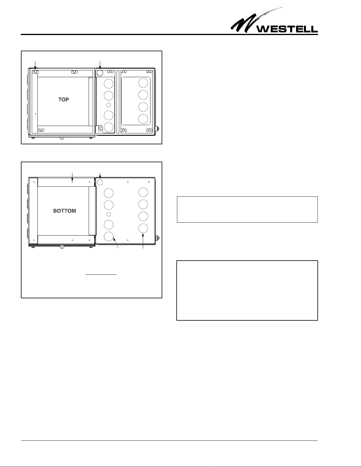
SVerify all required floor, ceiling, and wall cabinet knock-
outs have been removed (see the KNOCK-OUT NOTE and
Paragraph 3.5.1), in all cabinets.
SSelect a mounting location that is dry, grade level or high-
er, and will support a 63" X 52" concrete pad (min). These
dimensions include 1 foot of concrete to extend out from
each side of the conjoined units.
SIf placing the concrete pad next to an adjacent structure,
Westell suggests a 24" distance between the cable access
door panel and any structure to allow for easy cable access.
Verify the cabinet doors can be fully opened.
- CONCRETE PAD MOUNT NOTE -
For concrete pad mounting, prepare and pour the concrete pad
(and install the accompanying conduit or ductwork) per local
codes and company practices, insert anchors in the wet concrete
precisely where holes at the bottom of the battery box are located
(holes are 0.344" in diameter), and allow the concrete to dry,
prior to mounting the Boxer units. Westell recommends using the
pad mount kit to facilitate precise anchor placement.
- CONCRETE PAD HEIGHT NOTE -
The pad location must be grade-level or above - it must not be be-
low grade-level. The location must be able to support the com-
bined weight of the conjoined Boxer cabinets/box and all internal
equipment, including batteries. Always follow local installation
codes, procedures, and practices.
Concrete Pad Mounting Steps
1. Determine exact concrete pad location. Select and prepare
the location for the concrete pad, per company practice
and local codes. When determining the size of the pad, al-
low for 12" of concrete to extend out from each side of the
battery box (so the overall pad length and width measure-
ments are 2 feet wider than the battery box).
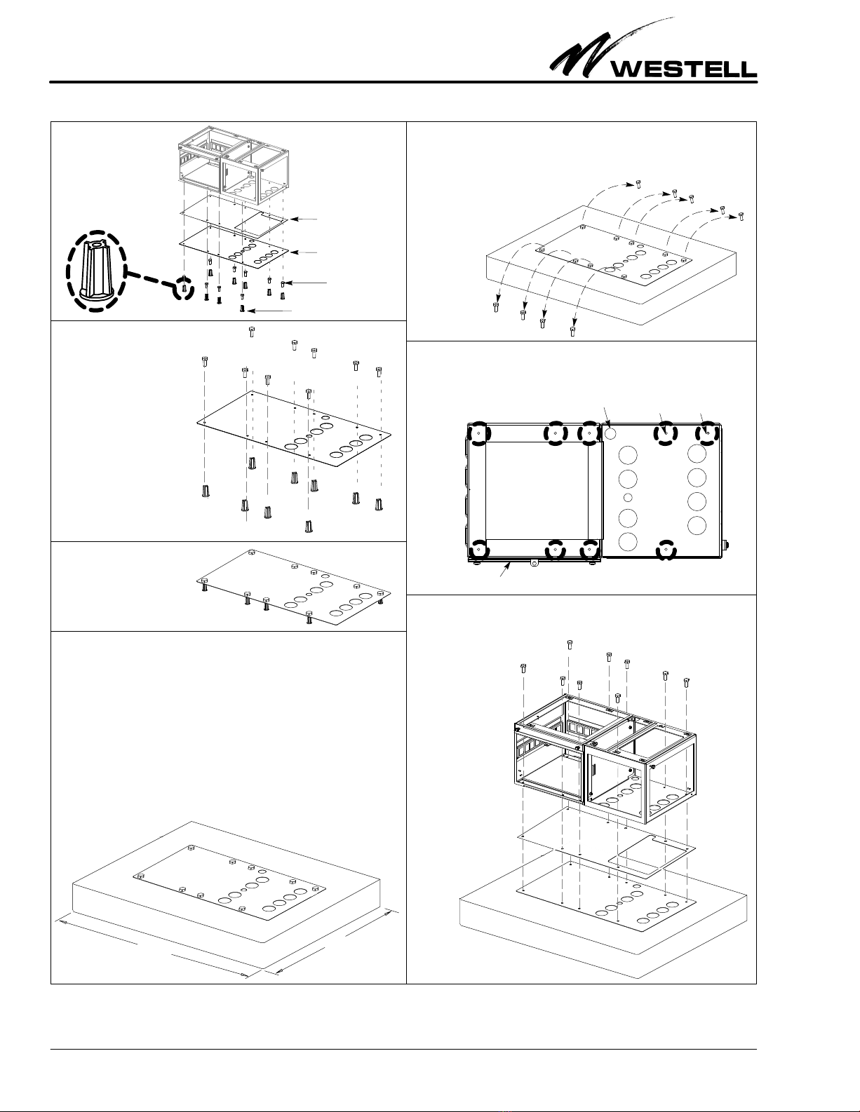
2. Prepare template. Perform Steps 1-3 of Figure 9.
3. Prepare the pad for conduit or ductwork. Dig and frame
the pad location per company practice. Once the pad is
framed for concrete, but before pouring gravel or con-
crete, install any cable conduit or ductwork that is desired
to be routed through the concrete and which will enter the
battery box from the bottom.
4. Prepare the pad for concrete (add gravel). Fill and com-
pact the pad site with gravel, per company practice.
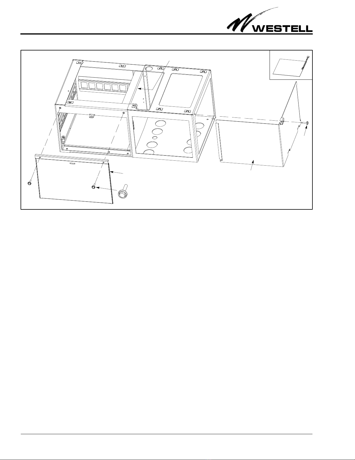
5. Prepare and join all Boxer units. If not already done, per-
form the steps in Paragraph 3.5.2 to open all Boxer units,
to locate the bag of hardware in the battery box, to remove
knock-outs, and to join the units.
6. Pour concrete, place the template, then set insulator gas-
ket and battery box on dry concrete. Perform Steps 4-7 of
Figure 9 to pour the concrete, to place the template (with
anchors attached) on the wet concrete, and once the con-
crete dries, to place the insulator gasket and conjoined
Boxer units on the dry cured concrete.
7. Test installation firmness. Test the installation by attempt-
ing to move the conjoined units. Correct any looseness.
8. Determine next step. Proceed to Paragraph 3.6, 3.7, or 3.8
to make ground connections, to install conduit, ductwork,
fittings, and or cables, and make battery connections.
- GROUNDING NOTE -
Always follow local safety precautions and standard operating
procedures for grounding the equipment when installing, up-
grading, repairing or maintaining equipment. Any instructions or
information contained herein is subordinate to local codes, oper-
ating procedures or practices.
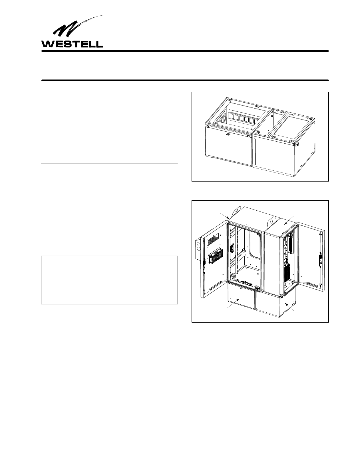
3.6 Making Ground Connections
As the battery box is designed to be mounted with a Boxer
equipment cabinet and side car cabinet, ground lugs and post
are not provided in the battery box itself, but instead provided
in the cabinets mounted above it. However, earth ground pro-
visions and connections must be considered when installing the
conjoined units, and earth ground should be brought up
through the bottom of the battery box similar to all other cable-
type access (such as electrical and signaling). Copper ground
lugs that accommodate #6 to #14 gauge wire are provided on
a ground plate on the interior floor of the Boxer equipment
cabinet (see Figure 10). Also on the plate are eight sets of bond
posts. One set of posts should be populated with a ground strap
to the side car cabinet.
To ground the battery box to the equipment cabinet’s ground
plate, two bonds straps (provided) must be installed, as ex-
plained in the steps that follow.
1. Locate the bond straps. Find the bond straps that are pro-
vided in the kit shipped with the battery box. One bond
strap is to be installed inside the battery box, and one is
installed in the cabinet, at the bottom. Note that each ring
end of each strap has a hole in it, and also note that one
hole is larger than the other.
2. Install small end of the cabinet bond strap. Install the ring
end with the smaller hole around a post on the Boxer
equipment cabinet’s ground plate.

Section BXB-19D-20A 030-100689 Rev. A R
81009IARA
Install battery box.
Once the battery box holes are aligned with the matching holes in
the template, set the battery box on top of the insulating gasket
and template. When the
holes are aligned, insert a
bolt through each |
set of aligned holes,
and drive the bolts
into the threads of
the anchors in the
concrete under the
template. Tighten
all bolts securely,
and test the
installation
stability by
attempting to
move or wiggle
the box.
Tighten any
looseness.
Prepare concrete pad and place template on pad.
Dig and frame the pad location per company practice. Allow for 12"
of concrete past the perimeter walls of the template (a 48" wide by
42" deep pad is suggested). Once the pad is framed for concrete,
but before pouring gravel or concrete, install any cable conduit or
ductwork that is desired to be routed through the concrete and which
will enter the battery box from the bottom. Fill and compact the pad
site with gravel per company practice. Pour concrete and level to
grade or slightly above − the top surface of the pad must not be be-
low grade level. While the concrete is wet, set the template onto the
top surface of the concrete, being sure the anchors are fully im-
mersed and surrounded by wet concrete. Remove any spilled con-
crete from the top of the template or from the bolts before it dries.
After concrete dries, remove bolts. When the concrete is
cured, remove the bolts.
If the insulating gasket is used (shown in Step 1), place it on top of
the template, and be sure it does not cover
the holes in the template below it
where conduit, innerduct or
cable access holes are
desired.
Ð
52"
63"
Align all holes in bottom of battery box with all anchor
holes. Locate the nine small holes at the bottom of the box. Align
the holes in the bottom of the box with the holes in the pad, tem-
plate, gasket, and the anchors.
Figure 9. Concrete Pad Mounting
Í
Ê
Ë
Î
Ï
Examine kit
contents. Locate the
A90-BXA-19PT2 pad
mount template kit
and examine and
separate all parts.
Ì
Align bolts, holes,
and anchors. Insert
bolts through the 9
holes in the galva-
nized template, align
each screw with an
anchor, and firmly
tighten the bolt to the
anchor, with the tem-
plate between them.
See Figure 20 for
template dimensions
and hole sizes.
Galvanized
template
9 Bolts
9 Concrete anchors
Affix anchors
and bolts to tem-
plate. Firmly tighten
the bolts to the an-
chors, with the tem-
plate between them.
Bottom view of battery box
Holes for anchors
1.5" hole for
AC conduit
Front door panel of
battery compartment
Insulating gasket

Section BXB-19D-20A
030-100689 Rev. A
R
9
1009IARA
Figure 10. Ground Plate Location in Main Cabinet
Install small ring
end of a bond strap
to a ground post
Small ring
end
Large ring end
of bond strap
Ground plate
location
Ground plate
3. Install large end. Install the ring end with the smaller hole
between a provided washer and screw, in the bottom front
left corner in the cabinet, as shown in Figure 10.
4. Install battery box bond strap. As shown in Figure 11, at-
tach the small end of the other bond strap to the downward
facing post provided for it on the top flange of the battery
box near the left wall. Attach the large end of the strap to
the bolt that enters the top left front corner of the battery
box from the cabinet above. This bolt also secures the
bond strap located inside the equipment cabinet above.
Secure the bond strap with the provided nuts.
5. Route earth ground wire to main Boxer cabinet ground
plate. Run an earth ground wire into the battery box up
through the cable compartment, through a knock-out in
the main cabinet above the battery box, and to the desired
ground lug in the ground plate of the equipment cabinet.
6. Seal the earth ground entrance hole. Depending on the
type of fitting or grommet used, it may be necessary to seal
the ground wire entrance hole, as stated in the note below.
- NOTE -
To improve the integrity of the cable entry seals when rubber
grommets are used, a water-proof foam or silicone sealant
should be used on the interior side of the cabinet, around the ex-
posed grommet and cable entry.
Figure 11. Installing Battery Box Bond Strap
Bolt Bond Strap
Washer
Large Ring End
Large ring end
of cabinet bond strap
Rubber-backed
washer
Bolt
Battery Box
(insert through cabinet
and battery box)
Bond Strap
(secure one end of bond
Battery Box
strap to this post)
(secure one end of
bond strap to bolt
inserted from above)
Cabinet
3.7 Making Cable Access Compartment Connec-
tions (Installing Fittings and Conduit)
3.7.1 When a battery box is attached to a Boxer cabinet
above it, extra lengths of cables and conduit are needed for the
additional height distance of the battery box, and an additional
AC fitting may be used at the bottom floor of the battery box.
Make these additional connections per company practice. At-
tach any grommets, conduit, innerducts, and/or fittings in the
appropriate knock-out holes in the upper cabinets.
3.7.2 Route and feed cables through the conduit and the
cable access compartment of the battery box, all per company
practice. Also gently feed/pull the communications cable(s), if
available at this time, from the outside up through the liquid-
tight tubing or steel conduit to the inside, allowing an adequate
amount of slack in the cable to secure to connectors at a later

Section BXB-19D-20A 030-100689 Rev. A R
10 1009IARA
Figure 12. Battery Cable
AC plug
DC Power, Red, Positive lead
(to +V on battery charger)
DC Power, Black, Negative
lead (to -V on battery charger)
Lock nut
Waterproof Grommet
(special plastic fitting
with threaded coupler)
Battery quick-
disconnect
Temperature
sensor probe
connector
Battery heater
pad connector
Temperature sensor probe connector
Battery ring
connectors
A
B
C
D
E
F
G
H
main Boxer cabinet
Battery End of Cable
to
Battery Compartment
Power End of Cable
to
time. If conduit is not required and only exposed cabling is
installed, rubber grommets can be used to seal the communica-
tions cabling in the cabinet.
3.8 Making Battery Compartment Connections
To make battery connections in the battery compartment, a
battery heater pad (optional), batteries, and battery cable must
be installed. The paragraphs below provide a description of
these procedures.
3.8.1 Installing the Heater Pad (optional)
An optional battery heater pad can be ordered and used with
the battery box. If used, unroll the heater pad. Place the heater
pad into the bottom of the battery compartment (Figure 13),
connector cable side up, and connector end on the right side of
the tray. Spread out the pad to cover the compartment floor.
Connect the heater pad’s connector to the battery cable (Con-
nector C in Figure 12) in Paragraph 3.8.2 after the battery cable
is installed.
3.8.2 Installing the Battery Cable
A special battery cable (Figure 12) is shipped with the battery
box, to facilitate backup battery connections. The battery
compartment end of this cable contains 4 connectors (shown as
connectors A, B, C, D in Figure 12), which are connected to the
batteries and the battery heater pad in the battery compart-
ment. The power end of the cable also contains 4 connectors
(shown as connectors E, F, G, and H in Figure 12), which are
connected to AC and DC power connectors in the main cabinet
above the battery box. The middle of the cable contains a spe-
cial grommet (fitting with a threaded coupler and lock nut)
which is installed in the hole at the bottom of the Boxer main
cabinet. Follow the steps below to connect the battery cable.
1. Locate battery cable. Find the battery cable located inside
the kit of parts shipped with the battery box, and remove
it from its protective wrapping. Note the special water-
proof grommet and nut in the middle area of the cable.
2. Remove knock-out in main Boxer cabinet. If not already
removed, locate the main cabinet’s bottom knock-out that
is provided for the battery cable and remove the knock-
out.
3. Remove nut from battery cable’s middle grommet. Un-
screw and remove the lock nut from the threaded end of
the special grommet in the middle of the battery cable.
4. Route power end of cable into the the main Boxer cabinet.
Starting inside the battery box battery compartment,
route the Power or main cabinet end of the cable (with the
E, F, G, and H power connectors) up through the previous-
ly removed grommet lock nut installed in the knock-out
hole in the cabinet, and into the main boxer cabinet. Pull
the battery cable up as far as it will go, until the special
grommet in the middle of the cable abuts the hole edges
and the threaded part protrudes into the main cabinet.
5. Secure cable’s middle grommet in the knock-out hole.
Press and hold the cable’s special grommet against the
knock-out hole and screw the threaded lock nut back onto
the threaded part of the grommet. Fully tighten the nut.
6. Install optional battery heater pad. Install the optional
battery heater pad, if ordered or equipped. Place the pad
on the battery compartment floor, with the cable/connec-
tor end facing to the right (it should abut the divider wall
between compartments).
7. Connect heater pad to battery cable. Locate the connector
at the end of the heater pad cable and connect it to Con-
nector C of the battery cable.

Section BXB-19D-20A
030-100689 Rev. A
R
11
1009IARA
Figure 13. Placing Batteries in Battery Compartment
Batteries (not provided)
Tie-down 34.5"
11.1"
13.25"
Battery Compartment
Use battery spacer block
if using smaller batteries
at rear of battery compartment
Slot to tie battery strap
After batteries are installed,
tie them down using the
provided tie-down strap:
railings
Pass the strap through the left wall
tie-down railing, route the strap
around the front and right side of the
battery group, then pass the strap
through a back wall railing (or the
right divider wall railing), then clip the
strap ends/connectors together and
tighten the strap, to snug the batteries
up against the rear and left walls of
the compartment.
Cable Compartment
Battery heater pad (optional)
(Place in battery compartment
before batteries)
Installed
Cable Compartment
18.6"
14"
Secures block to
divider wall
Pad
connector
cable
17"
18"
18"
batteries 16.5"
8. Connect AC plug to AC duplex outlet in main cabinet. In
the equipment cabinet, insert the battery cable’s AC plug
(Connector E) into the AC duplex outlet at the bottom of
the cabinet.
9. Connect temperature sensor probe connector to battery
charger. Locate connector F of the battery cable and con-
nect it to the appropriate connector of the battery charger
(rectifier) in the cabinet.
3.8.3 Installing the Batteries
Before battery installation, first install the battery cable by per-
forming the steps in Paragraph 3.8.2, then install the optional
heater pad (see Figure 13), then install the batteries, per com-
pany practice or per the steps below. The total battery weight
cannot exceed 250 pounds. See Figure 13 and Table 1 for bat-
tery compartment dimensions.
1. Select batteries. Select the appropriate size and type of
batteries per company practice and per the equipment re-
quirements.
2. Install the optional battery spacer block. To h e l p i n s u r e a
snug battery fit, install the optional battery spacer block if
the batteries are small enough to accommodate the instal-
lation of all the batteries plus the spacer block. The left
wall tie-down railing can be used to adjust the installation
depth of this spacer block. Orient the block as shown in
Figure 13, and insert the left side flange of the block into
the left-wall tie-down railing, per the battery depth. Se-
cure the right side of the block to the holes located in the
compartment divider wall.
3. Verify the optional battery heater pad is installed. If using
the optional battery heater pad, install it per Step 6 in
Paragraph 3.8.2.
4. Place batteries in the battery compartment. Gently place
the batteries in the battery compartment, on top of the op-
tional installed heater pad. Press the batteries up against
the left and rear compartment walls (or the battery spacer
block). Do not place a battery on the heater pad cable or
connector, to avoid possible damage.
5. Jumper the batteries together. Jumper the batteries to-
gether, per company practice.
6. Connect battery cable connectors to batteries. In the bat-
tery compartment, locate Connectors A and B of the
battery cable (see Figure 12) and connect them to the
proper battery terminals, per company practice.
7. Make battery compartment temperature sensor connec-
tions. Locate the battery compartment’s temperature
sensor cable (install it if not pre-installed with the batter-
ies) and connect it to Connector D of the battery cable.
8. Connect DC leads to screw terminals of battery charger
(user provided). Locate the battery cable’s DC leads (G
and H in Figure 12) and connect them to the screw termi-
nals of the battery charger’s DC screw terminal strip, per
company practice. Connect the red positive lead to the +V
screw terminal, and connect the black negative lead to the
-V terminal.
3.8.4 Installing the Battery Tie-down Strap
Once the batteries are placed in the battery compartment, use
the provided battery strap to secure the batteries in place. To

Section BXB-19D-20A 030-100689 Rev. A R
12 1009IARA
Figure 14. Clean the Air Intake/Exhaust Vents or Louvers
Remove any debris
from all vents
Vents on
left side of
battery box
secure the strap, pass the strap through the left wall tie-down
railing, route the strap around the front then right side of the
battery group, pass the strap through a back wall (or the right
divider wall) railing, then fasten the strap ends/connectors to-
gether and tighten the strap, to snug the batteries up against the
rear and left walls of the compartment. Tighten the strap to re-
move any slack. Examine the strap to verify there is no strap
kinking, binding, or slack.
3.9 Testing the Battery Box Connections
Perform system power-up per company practice or per the in-
structions in the main Boxer cabinet documentation. If trouble
is encountered, verify all battery cable connections are secure
and tight and have good contact or connection.
3.10 Closing and Locking the Cabinets
Upon completion, the installer should close and lock the Boxer
cabinet and the battery box by replacing both compartment
door panels and tightening the cup-washer screws with a can
wrench or 216 tool. The battery box compartment panel op-
tionally can be locked with a padlock (customer supplied) via
a hole provided in the provided padlock flange. Pick up any
tools and materials at the installation site, and clean the site of
any trash or debris.
4. MAINTENANCE
- CAUTION -
To avoid electrical shock, turn off any DC or AC power feeds
before servicing the unit.
4.1 Replacing the Battery Cable
If the battery cable is not working properly, it can be replaced
by disconnecting it and installing a new one. See Table 2 for or-
dering information. Always disconnect power at the source
before removing the battery cable.
4.2 Inspection and Debris Removal
WestellrBoxertbattery box components are maintenance-
free, however, at least once every six months, inspect Boxer to
remove any debris from the vents or louvers (Figure 14). This
facilitates proper operation of the cabinet and battery box and
allows unobstructed air flow.
5. CUSTOMER & TECHNICAL SERVICES
5.1 Customer Service & Technical Assistance
If technical or customer assistance is required, contact Westell
by calling or using one of the following options:
Voice: (800) 377-8766
email: [email protected]
For additional information about Westell, visit the Westell
World Wide Web site at http://www.Westell.com.
5.2 Part Numbers
This equipment is identified by a part number
(A90-BXB19-D), which consists of three parts: the equipment
issue letter (A), the assembly type (90), and the model number
(BXB19-D). Each time a change is made to the product which
changes the form, fit, or function of the product, the issue letter
is incremented by one. Be sure to indicate the issue level as well
as the model number when making inquiries about the equip-
ment.
Physical Feature U.S. Metric
Height 14 in. 35.60 cm
Width (including vents) 34.5 in. 87.63 cm
Depth (excluding lock hardware) 18.60 in. 47.24 cm
Height (battery compartment) 13.25 in. 33.70 cm
Width (battery compartment) 18 in. 45.70 cm
Depth (battery compartment) 18 in. 45.70 cm
Height (cable compartment) 14 in. 35.60 cm
Width (cable compartment) 16.50 in. 41.90 cm
Depth (cable compartment) 18 in. 45.70 cm
Weight (empty, approx.) 30 lbs. 13.6 kg
Weight Load (Max.) 250 lbs. 113.4 kg
Outside Operating Temp. -40°to 115°F -40°to 46°C
Internal cabinet Temp. -40°to 149°F -40°to 65°C
Humidity 0 to 95% (non-condensing)
Table 1. Boxer Battery Box Physical Specifications
6. WARRANTY & RETURNS
6.1 Warranty
Westell warrants this product to be defect-free at shipment
time. Westell also warrants this product to be fully functional

Section BXB-19D-20A
030-100689 Rev. A
R
13
1009IARA
for the time period specified by the terms and conditions gov-
erning the sale of the product. Equipment
repairs/modification attempts by an unauthorized person will
void the warranty.
6.2 Return and Replacement Policy
Westell will repair or replace any defective Westell equipment
without cost during the warranty period if the unit is defective
for any reason other than abuse, improper use, or improper
installation. To return defective equipment, first request a Re-
turn Material Authorization (RMA) number from Westell by
calling or using one of the options shown below. Once an RMA
number is obtained, return the defective unit (freight prepaid),
along with a brief problem description, to the address we will
provide to you when you contact us.
Voice: (630) 375-4211
email: [email protected]
Replacements will be shipped in the fastest manner consistent
with the urgency of the situation. Westell will continue to repair
or replace faulty equipment beyond the warranty period for a
nominal charge. Contact Westell for details.
7. SPECIFICATIONS
7.1 Regulatory/Agency Specifications
SNEMA 3R
7.2 Ordering Specifications
To order units, call the telephone number shown in Paragraph
5.1 and specify a specific model number shown in Table 2.
7.3 Physical Specifications
The physical specifications are shown in Table 1.
Part # Description
A90-BXB19-D WestellrBoxertBattery Box (for use with
and mounting under a 20-RU Westell Box-
er cabinet and a Boxer side car cabinet).
Has knock-out pattern that matches
knock-out hole pattern in the cabinets
mounted above it. Includes a battery spacing
block, and a kit of parts that includes a multi-
connector battery cable assembly, 2 bond
straps, a battery tie-down strap, and a bag of
hardware (screws, washers, and lock nuts) to
attach battery box to the two cabinets mounted
above it.
A90-BXB19-C Same as A90-BXB19-D but for use with
and mounting under the 10-RU Westell
Boxer cabinet (without a side car cabinet).
A90-BXB19-A Same as the A90-BXB19-C but without the
matching knock-out hole pattern (has
large hole in floor instead).
A90-BXB19-B Same as the A90-BXB19-A but includes a
battery heater pad.
Options & Other Boxer Family Models
A90-BXM2019-4HE Boxert400W, -48VDC heat exchanger
cooling, 20RU 19" rack, AC & GFI outlets,
screw-down rear-access panel
A90-BXMSC-20A Boxertside car customer demarcation
cabinet, used with and attaches to the
right side of a Boxer 20RU main cabinet.
Side car contents and part numbers are
specific to customer requirements. Con-
tact your Westell representative for addi-
tional information.
A90-BXS19-14 Boxer Skirt, for mounting under a 10-RU
(or 20-RU) Boxer cabinet.
A90-BXA-19PT2 Pad mount kit.
A90-BXA-HP01 Heater pad for batteries.
A90-BXA-WH03 Wall or H-Frame mounting kit for 20-RU
Boxer
Replacement Parts
023-800281 Replacement battery cable assembly.
001-000371 Cabinet matching touch-up paint. Apply
per company practice.
Table 2. Ordering and Option Information

Section BXB-19D-20A 030-100689 Rev. A R
14 1009IARA
Appendix A − Product Views
Figure 15. Front View of Battery Box
34.5"
18" 16.5"
14"
Figure 16. Right Side Boxer Battery Box
18"
14"

Section BXB-19D-20A
030-100689 Rev. A
R
15
1009IARA
Figure 17. Top View, Battery Box
Figure 18. Bottom View, Battery Box
1.8" diameter (1 place)

Section BXB-19D-20A 030-100689 Rev. A R
16 1009IARA
Figure 20. Concrete Pad Mount Template Dimensions (Top View)

Section BXB-19D-20A
030-100689 Rev. A
R
17
1009IARA
Figure 21. Front Conjoined View of Boxer Battery Box, 20-RU Equipment Cabinet, and Side Car Cabinet
Boxer Battery Box
Boxer Cabinet

Section BXB-19D-20A 030-100689 Rev. A R
18 1009IARA
Figure 22. Front Conjoined View of Boxer Battery Box, 20-RU Equipment Cabinet, and Side Car Cabinet (Doors Open 90_)
Boxer Battery
Box
Boxer
Cabinet

Section BXB-19D-20A
030-100689 Rev. A
R
19
1009IARA
Figure 23. Rear Conjoined View of Boxer Battery Box, 20-RU Equipment Cabinet, and Side Car Cabinet
Boxer Battery Box
Boxer Cabinet
Rear Access Panel Removed

Section BXB-19D-20A 030-100689 Rev. A R
20 1009IARA
Figure 24. Right Side View of Conjoined Boxer Battery Box, 20-RU Equipment Cabinet, and Side Car Cabinet
Boxer Battery Box
Boxer Side Car Cabinet
This manual suits for next models
1
Table of contents