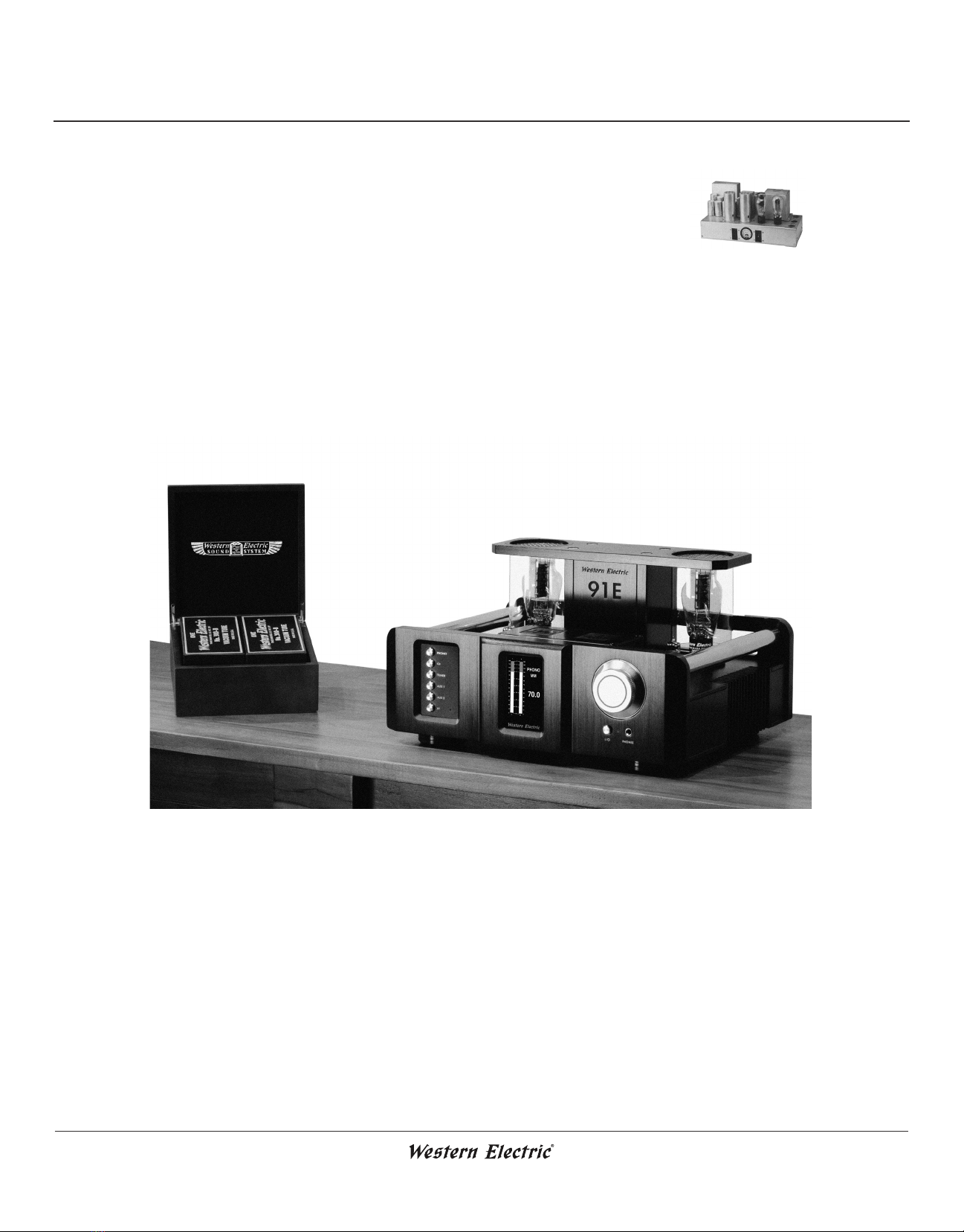
TYPE 91E
INTEGRATED AMPLIFIER
TABLE OF CONTENTS
INTRODUCTION
Type 91E Integrated Amplier ..................................................................................................... 1
Replica Tubes Disclaimer .............................................................................................................. 1
NOTES FROM THE MANUFACTURER
Patented Steered Current Source Technology (SCS).................................................................... 2
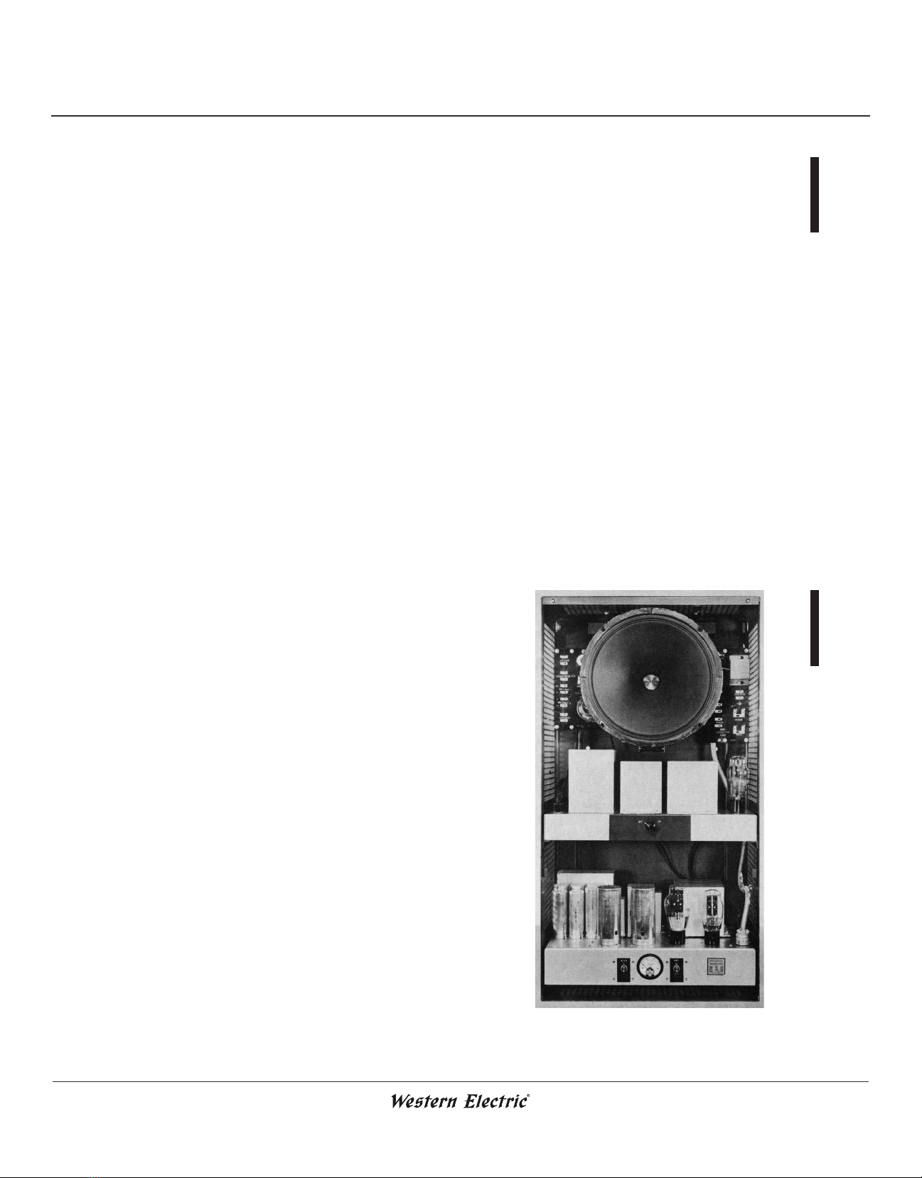
Type 91 - Family History.............................................................................................................. 2
FEATURES & SPECIFICATIONS
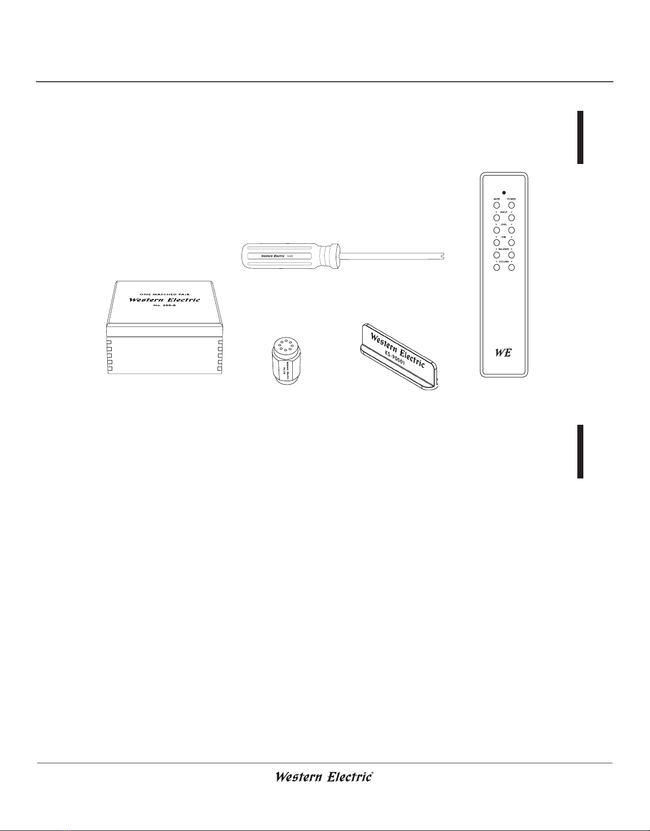
In the Box...................................................................................................................................... 4
Features Overview......................................................................................................................... 4
Amplier Data .............................................................................................................................. 5
OPERATION & SAFETY
Top Panel Diagram ....................................................................................................................... 7
Electron Tube Installation & Access ............................................................................................. 8
Front Panel Diagram................................................................................................................... 10
Rear Panel Diagram .................................................................................................................... 11
Basic Hookup Diagram............................................................................................................... 12
Mains Connection....................................................................................................................... 13
Power On & Startup ................................................................................................................... 13
Tube Auto-Bias........................................................................................................................... 13
Post-Startup ................................................................................................................................ 13
Auto-Standby (How to Disable)................................................................................................. 13
Wireless Connectivity (BT) ........................................................................................................ 14
Headphones................................................................................................................................. 14
Output Transformer Block.......................................................................................................... 14
Line Out & Pre-Out................................................................................................................... 15
Break-In Period........................................................................................................................... 15
Amplier Update Procedure........................................................................................................ 15
LCD Screen Functionality .......................................................................................................... 16
Phono Input & Terminations...................................................................................................... 17
Remote Control Operation ......................................................................................................... 17
Level Adjustment........................................................................................................................ 17
Balance Adjustment .................................................................................................................... 18
Remote Control Battery Replacement ........................................................................................ 18
Amplier Safety .......................................................................................................................... 19
Electron Tube Safety ................................................................................................................... 19
WARRANTY & SERVICE
Warranty Policy........................................................................................................................... 21
Product Service Policy & RMA Process...................................................................................... 23
Troubleshooting .......................................................................................................................... 24