Lit. No. 48163, Rev. 00 March 15, 2016
3
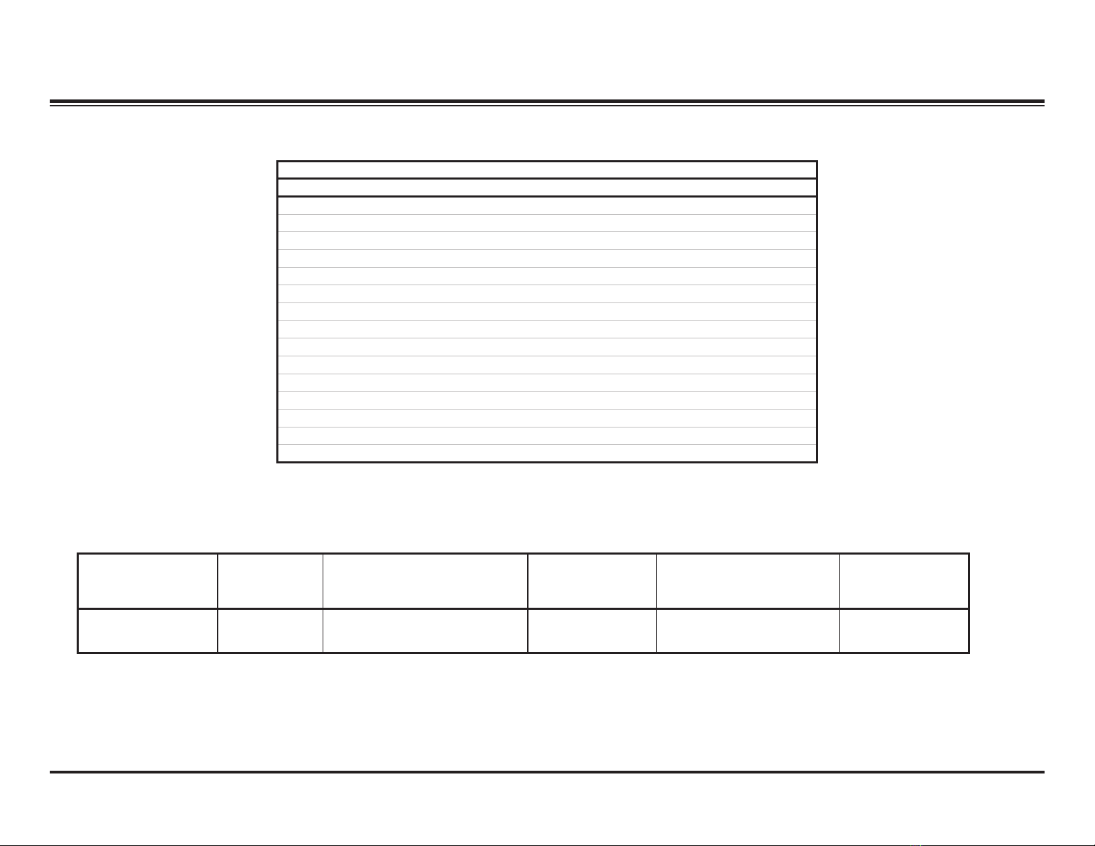
TABLE OF CONTENTS
SAFETY INFORMATION.............................................................................. 5–7
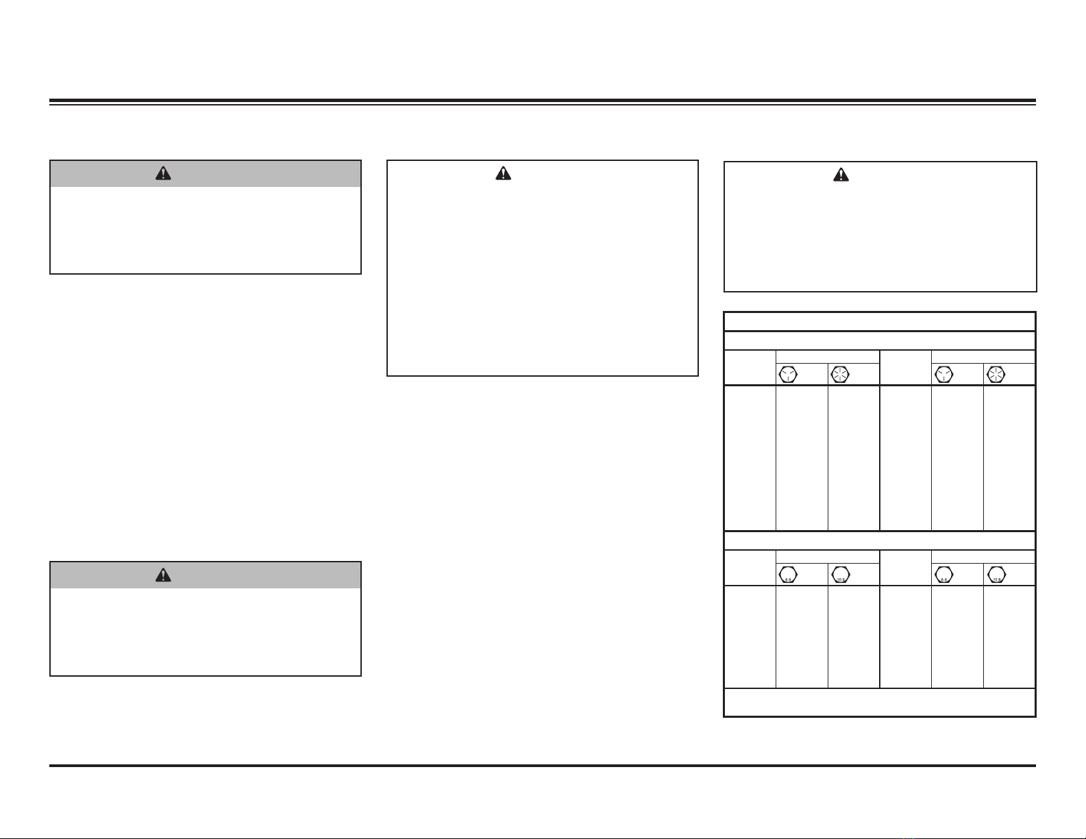
Torque Chart ................................................................................................7
INTRODUCTION................................................................................................8
Recommended Tools...................................................................................8
WESTERN®Service Kits Available..............................................................8
PRODUCT SPECIFICATIONS.................................................................... 9–10
Electrical System – Approximate Values ....................................................9
FloStat®Hydraulic System ...........................................................................9
Hydraulic Fastener Torque Specications .................................................10
Relief Valve Specications.........................................................................10
BLADE, A-FRAME & LIFT FRAME..........................................................11–13
Pivot Plate Conguration – UltraMount®...................................................11
Stand Shoe Height Adjustment – UltraMount...........................................11
Attaching A-Frame to Lift Frame – UltraMount®2 ....................................12
Stand Shoe Height Adjustment – UltraMount 2........................................13
OPERATIONAL ADJUSTMENTS.............................................................14 –17
Filling the Hydraulic Unit ............................................................................14
Blade Drop Speed Adjustment ..................................................................15
Vehicle Lighting Check ..............................................................................16
Headlamp Beam Aiming ............................................................................17
HYDRAULIC SYSTEM OVERVIEW......................................................... 18–24
FloStat Hydraulic Unit Components...........................................................18
Pilot-Operated (Poppet-Style) Check Valves.............................................19
Hose Routing .............................................................................................19
Hoses and Fittings Installation.................................................................. 20
Ram Seal Installation................................................................................ 20
Cartridge and Check Valve Removal.........................................................21
CONTROLS .............................................................................................. 22–30
Overview ................................................................................................... 22
Solenoid Joystick Control ......................................................................... 23
CabCommand Hand-Held Control.............................................................24
Joystick Control – FLEET FLEX System ..................................................25
CabCommand Hand-Held Control – FLEET FLEX System .....................27
SECURITY GUARD™ Snowplow Anti-Theft System ................................28
THEORY OF OPERATION....................................................................... 31–33
Snowplow Hydraulics.................................................................................31
3-Port Module Electrical ............................................................................31
Green Label Module (PN 29070-1) .......................................................32
Blue Label Module (PN 29760-1)......................................................... 33
ELECTRICAL & HYDRAULIC SCHEMATICS..........................................35 –74
Legend .......................................................................................................37
3-Plug System – Wiring Overview........................................................... 38
3-Plug System – Electrical Connectors.................................................. 39
3-Plug System Schematics....................................................................... 40
Electrical Schematic ............................................................................ 40
Low-Beam Headlamps with Snowplow Connected to Vehicle .............41
High-Beam Headlamps with Snowplow Connected to Vehicle ............42
Hydraulic Schematic ............................................................................ 43
Raise – Electrical ................................................................................ 44
Raise – Hydraulic ................................................................................ 45
Lower/Float – Electrical....................................................................... 46
Lower/Float – Hydraulic .......................................................................47
Angle Right – Electrical....................................................................... 48
Angle Right – Hydraulic ...................................................................... 49
Angle Left – Electrical......................................................................... 50
Angle Left – Hydraulic..........................................................................51
Hold in Raise Position – Hydraulic.......................................................52
Striking an Object While Plowing – DS............................................... 53
Striking an Object While Plowing – PS ............................................... 54