Western Telematic CAS-81 User manual

WTI Part Number: 12365
Rev. D
CAS-81
8-Port Code Activated Switch
Preliminary Draft
July 1995
User's Guide


Table of Contents
1. Introduction ...........................1-1
2. Unit Description .........................2-1
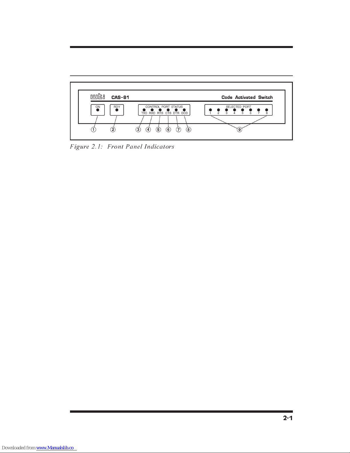
2.1. Front Panel Indicators .......................2-1
2.2. Back Panel .............................2-2
3. Installation ............................3-1
3.1. Set DIP Switches..........................3-1
3.1.1. Data Rate (Baud) Selection (Switches 1 through 3)..3-1
3.1.2. Timeout Selection (Switches 4 and 5) .........3-1
3.1.3. Quiet Mode (Switch 6) ..................3-2
3.1.4. Auto Connect Serial Port 1 (Switch 7) .........3-2
3.1.5. Broadcast Mode (Switch 8) ...............3-2
3.1.6. Force CTS (Switch 9)...................3-3
3.1.7. Force DCD (Switch 10)..................3-3
3.2. Connect Power Cable .......................3-3
3.3. Connect Devices to Serial Ports .................3-3
3.4. Connect Control Port .......................3-4
3.5. RS422 Line Driver Option ....................3-4
4. Operation .............................4-1
4.1. Power Up ..............................4-1
4.2. ASCII Characters .........................4-1
4.3. Command String ..........................4-2
4.4. Command Response ........................4-2
4.5. Port Gating .............................4-3
4.5.1. Open Port Gating .....................4-3
4.5.2. Close Port Gating .....................4-3
Appendices
A. Description of System Interfaces .............Apx-1
A.1. Control Port (DB25 Female) .................Apx-1
A.2. Serial Ports 1 through 8 (DB9 Male).............Apx-2
A.2.1. RS422 Line Driver Option ..............Apx-2
B. Specifications .........................Apx-3
C. FCC Notice ..........................Apx-4
D. Customer Service.......................Apx-5
i

List of Figures
2.1. Front Panel Indicators ........................................................................2-1
2.2. Back Panel............................................................................................2-2
A.1. Control Port / Serial Port Interface.............................................Apx-1
A.2. RS422 Option Interface ................................................................Apx-2
ii
Table of Contents

1. Introduction
The CAS-81 Code Activated Switch brings the convenience of
code-based RS232 switching to sites with multiple terminals,
printers, and peripherals. The CAS-81 enables a single RS232
Control Port to switch between 8 devices via an ASCII code
sequence.
Code based switching lets you control the CAS-81 from your PC
or mainframe. When a modem is attached to the Control Port,
the CAS-81 can also be managed from a remote location.
Devices can be connected or disconnected by sending commands
from a remote PC via modem.
The CAS-81 can operate at speeds up to 115,000 bps and passes
data in "real-time" with no delays. Binary and graphics files can
be safely passed due to the unique 8 character switch instruction,
which considerably reduces the chances of false switching.
A broadcast mode makes it easy to mass-address a group of
printers, display devices, or an array of laboratory instruments by
directing the data on the Control Port to all Serial Ports
simultaneously. The broadcast mode may be selected by code or
permanently selected by the Select Switch.
An Auto-connect feature allows the Control Port to automatically
connect to Serial Port 1 each time the unit is powered up, or after
a timeout or disconnect. This provides a data path to a critical
device in case of a power failure, or convenient connection to
commonly used equipment.
Each Serial Port may be configured for a balanced RS422 long
distance line driver by simply removing the socketed RS232
driver chip and plugging in an optional RS422 module. When
the module is installed, an LED on the back panel indicates the
port is RS422.
1-1

Applications
·Industrial Robotic and Numeric Control
·Remote Diagnostics
·Laboratory Equipment Polling
·Data Acquisition
·Network Management
Typographic Conventions
Throughout the manual, typefaces and characters have been used
to denote the following:
^(e.g. ^X) Indicates a key combination that is used
to invoke a command. For example, the
text "^X" (Control X) indicates that the
[Ctrl] key and the [X] key should be
pressed simultaneously.
COURIER FONT Indicates characters typed on the keyboard.
For example, ^VS or ^C#.
1-2
CAS-81 User's Guide

2. Unit Description
2.1. Front Panel Indicators
ÀON: Indicates power to the unit is ON.
ÁRDY: Indicates unit is Ready to operate. A steady blink
indicates that the CAS-81 is operating normally.
ÂTXD: Indicates that data is being received at Control Port
pin 2.
ÃRXD: Indicates that data is being transmitted out Control
Port pin 3. Also indicates that data is being received by
pin 2 of a selected Serial Port.
ÄRTS: Indicates that the "Request to Send" signal is present
at Control Port pin 4.
ÅCTS: Indicates that the "Clear to Send" signal is present at
Control Port pin 5. Also indicates that the "Clear to Send"
signal is present at pin 8 of a connected Serial Port.
Always high when all ports are disconnected.
ÆDTR: Indicates that the "Data Terminal Ready" signal is
present at Control Port pin 20.
ÇDCD: Indicates that the "Data Carrier Detect" signal is
present at Control Port pin 8. Also indicates that the "Data
Carrier Detect" signal is present at pin 1 of a connected
Serial Port. Always high when all ports are disconnected.
ÈSerial Ports1-8: Indicates that the corresponding
numbered Serial Port is currently connected.
2-1
Figure 2.1: Front Panel Indicators

2.2. Back Panel
ÀSerial Ports1-8: Eight RS232 DB9 male connectors
configured as DTE. Accepts a standard AT 9 pin to printer
or modem cable, depending on the application. Refer to
Appendix A for more information on the Serial Port
Interface.
Note that when the RS422 Line Driver Option has been
installed, the LED indicator above the Serial port will light
to indicate that the corresponding port is configured for
RS422 communication.
ÁControl Port: RS232 DB25 female connector configured
for DCE. Accepts a standard PC to Modem Cable.
The CAS-81 will respond to proper ASCII code strings
received by the Control Port. Once a port is selected, data
will pass between the Control Port and the selected Serial
Port. Refer to Appendix A for more information on the
Control Port interface.
ÂDefault Switch: A 10 position DIP switch that is used to
select the Control Port Data Rate, No-data timeout period,
and the Auto connect and broadcast features. This switch
is read upon power up.
ÃAC Power: AC power cord receptacle and ON/OFF
switch. The CAS-81 features a 100/240 VAC autosensing
universal power supply.
2-2
CAS-81 User's Guide
Figure 2.2: Back Panel

3. Installation
3.1. Set DIP Switches
The DIP Switches located on the CAS-81 back panel are used to
set the Data Rate, Timeout Selection, Quiet Mode, Broadcast
Mode, and other features. Note that a label on the underside of
the CAS-81 unit also describes DIP Switch settings.
3.1.1. Data Rate (Baud) Selection
(Switches 1 through 3)
Select the Baud Rate for the Control Port. The Baud Rate must
match that of the control device. The CAS-81 is transparent to
parity and will operate at 7 bits even or odd parity, and at 8 bits
no parity.
Switch Baud Rate
123
Down Down Down 1200
Up Down Down 2400
Down Up Down 4800
Up Up Down 9600
Down Down Up 19.2K
Up Down Up 38.4K
Down Up Up 57.6K
Up Up Up 115K
3.1.2. Timeout Selection (Switches 4 and 5)
Selects the No-Data-Activity disconnect period. If data has not
been received by the Control Port for the specified time period,
the selected Serial Port will close.
Switch Timeout Selection
45
Down Down Off
Up Down 5 Seconds
Down Up 30 Seconds
Up Up 60 Seconds
3-1

3.1.3. Quiet Mode (Switch 6)
When enabled, the CAS-81 will not respond with
"Connect/Disconnect" messages.
Switch 6 Quiet Mode
Up Enable
Down Disable
3.1.4. Auto Connect Serial Port 1 (Switch 7)
When enabled, automatically connects the Control Port to Serial
Port 1 on the following conditions:
1. Power Up
2. After a Timeout disconnect, if selected.
3. After a Code sequence disconnect.
Switch 7 Auto Connect Serial
Port 1
Up Enable
Down Disable
3.1.5. Broadcast Mode (Switch 8)
When enabled, permanently activates the Broadcast Mode. Data
from the Control Port will be sent out all eight Serial Ports. Note
that when the Broadcast Mode is active, all Serial Port Status
LEDs will be lit.
Data received by the selected Serial Ports will be "ord" and
passed out the Control Port. If data is received by two ports
simultaneously, data output may be garbled.
A broadcast one/all jumper located on the circuit board will
block received data from Serial Ports2-8. This feature allows
the Control Port to receive a response message from just one
device when broadcasting commands. Receiving data from
multiple devices simultaneously may cause garbled data.
Switch 8 Broadcast Mode
Up Enable
Down Disable
3-2
CAS-81 User's Guide

3.1.6. Force CTS (Switch 9)
When enabled, forces the Control Port CTS pin to high.
Switch 9 Force CTS High
Down Enable
Up Disable
3.1.7. Force DCD (Switch 10)
When enabled, forces the Control Port DCD pin to high.
Switch 10 Force DCD High
Down Enable
Up Disable
3.2. Connect Power Cable
Make certain the power switch is set in the OFF position, then
connect the power cable to the power cable receptacle. Connect
the other end of the cable to a grounded AC wall outlet.
CAUTIONS:
·This device should only be operated with the type
of power source indicated on the instrument
nameplate. If you are not sure of the type of
power service available, please contact your local
power company.
·Reliable earthing (grounding) of this unit must be
maintained. Particular attention should be given
to supply connections when connecting to power
strips, rather than directly to the branch circuit.
3.3. Connect Devices to Serial Ports
Serial Ports1-8arewired as standard AT 9 pin COM Ports.
Connect data cables from the desired devices to Serial Ports 1
through 8. The Serial Ports accept AT 9 pin to printer or modem
cables, depending on the application.
CAUTION:
Make certain that all data cables are compatible
with the CAS-81 Serial Port interface. Please refer
to Appendix A for a description of the Serial Port
interface.
3-3
Installation

3.4. Connect Control Port
The Control Port is configured to appear as a 25 pin DCE modem
and accepts a standard PC to Modem straight wired cable. Use a
"Null Modem Cable" to connect a modem to the Control Port.
For a description of the Control Port Interface, please refer to
Appendix A.
3.5. RS422 Line Driver Option
Each Serial Port may be configured with an optional RS422
balanced line driver. These long distance line drivers can extend
high speed transmission distance to 4,000 feet using 2 twisted
pair wiring. Only the TXD and RXD signals are transmitted.
The DCD and CTS signals are set to high.
To install the optional RS422 module, simply remove the RS232
Driver chip located on the circuit board adjacent to the desired
Serial Port’s connector and plug in the RS422 module. An LED
viewed from the back panel will indicate that the port is RS422.
Please refer to Appendix A for a description of the RS422 Serial
Port interface.
3-4
CAS-81 User's Guide

4. Operation
4.1. Power Up
The ON LED indicates that AC Power has been turned on. The
RDY LED indicates that the processor is operating and the unit is
READY to operate. A flickering RDY LED indicates an AC
Power brown out condition. The Control Port Status LEDs
indicate the signal status of the Control Port. The Serial Port
LEDs indicate the port(s) selected. When all Serial Port LEDs
are lit, this indicates that CAS-81's Broadcast Mode is active.
Upon power-up, the unit is programmed according to the
parameters selected by the setup DIP switches, which are located
next to the Control Port. (Refer to switch setup section). If you
change any of the DIP Switch settings while the unit is powered
on, you must turn power off and on to re-read the switch.
4.2. ASCII Characters
The PC or controlling device connected to the Control Port must
send ASCII characters at the same data rate as the CAS-81. The
unit accepts 8 bits / no parity, or 7 bits / even parity.
4-1

4.3. Command String
The command string consists of seven contiguous characters.
The first 6 characters are ASCII Control codes, and the seventh
is the configuration code.
^V^X^X^V^X^Xn (Command String)
Where:
n= 0 Disconnects
n=1-8 Selects Serial Port Number 1
through 8
n= 9 Enables Broadcast Mode
(Select All Serial Ports)
Note that if "n" equals any character other than 0 through 9, the
command will be terminated.
Examples:
To select port 3, send the following command:
^V^X^X^V^X^X3
To disconnect, send the following command:
^V^X^X^V^X^X0
4.4. Command Response
Upon receiving a valid command string, the CAS-81 will send an
acknowledgment message out the Control Port. The message is
sent as 8 bits / no parity. Acknowledgment messages are as
follows:
Connected <CR>/<LF>
Disconnected <CR>/<LF>
Broadcast <CR>/<LF>
Note that the Command Response can be disabled by placing DIP
Switch 6 in the UP position to enable the Quiet Mode feature.
When the Quiet Mode is active, the unit will not send
acknowledgment messages.
4-2
CAS-81 User's Guide

4.5. Port Gating
With all ports closed, data received by the Control Port will not
be passed to any of the Serial Ports. Any data received by the
Serial Ports will not be passed to the Control Port. The CTS and
DCD signals will always be set high.
4.5.1. Open Port Gating
Upon receiving a valid command string at data rates up to 19,200
bps, the selected Serial Port will open during the stop bit time of
the configuration code thus allowing the next character to be
passed out the selected port.
For data rates above 19,200 bps it is necessary to delay
approximately 1 millisecond before sending data out the selected
Serial Port. This prevents a character that immediately follows
the configuration character from being "cut in half".
4.5.2. Close Port Gating
Selected Serial Ports can be closed using three methods:
1. By using the Command String to select another Serial Port.
2. By Using the Command String to disconnect.
3. By using the No-Data-Activity timeout feature.
In methods 1 and 2, the Command String Control Codes will be
passed out the selected Serial Port. The Serial Port(s) will close
immediately after the sixth character, thus blocking the next
character from being sent. If the configuration character was 1 -
8, then the selected Serial Port would open. If the configuration
character was 0 then the ports would remain closed.
The No-Data-Activity timeout feature can be used to make a
"clean" close if the Command String Control Codes cause a
conflict with the connected devices. The Serial Port will
automatically close if no data is received from the Control Port
for the time period selected by the setup switch.
4-3
Operation

4-4
CAS-81 User's Guide

A. Description of System
Interfaces
A.1. Control Port (DB25 Female)
The Control Port is a 25 pin female connector wired in a DCE
(modem) configuration.
Pin Signal I/O Not
Connected Connected
2 RXD Input - To Serial Port Pin 3
3 TXD Output Low Follows Serial Port
4 RTS Input - To Serial Port Pin 7
5 CTS Output High * Follows Serial Port
6 DSR Output High Always High
7 GND Signal Ground
8 DCD Output Low * Follows Serial Port
20 DTR Input - To Serial Port Pin 4
* May be forced high by DIP Switches 9 and 10. Always
high when all Serial Ports are connected.
Apx-1
Figure A.1: Control Port / Serial Port Interface

A.2. Serial Ports 1 through 8 (DB9 Male)
The Serial Ports are 9 pin male, wired in a DTE configuration
similar to that of an A computer. Figure A.1 and the table below
describe the Serial Port interface.
Pin Signal I/O Not
Connected Connected
1 DCD Input - To Control Port Pin 8
2 RXD Input - To Control Port Pin 3
3 TXD Output Low Follows Control Port Pin 2
4 DTR Output Low Follows Control Port Pin 20
5 GND Signal Ground
6 Open
7 RTS Output Low Follows Control Port Pin 4
8 CTS Input - To Control Port Pin 5
9 Open
A.2.1. RS422 Line Driver Option
Each Serial Port may be configured with an RS422 balanced line
driver. These long distance line drivers can extend high speed
transmission distance to 4,000 feet using 2 twisted pair wiring.
Only the TXD and RXD signals are transmitted. The DCD and
CTS signals are set to high. Figure A.2 below describes the
RS422 Serial Port interface.
Note: Handshake signals are not passed. All other pins are open.
Apx-2
CAS-81 User's Guide
Figure A.2: RS422 Option Interface

B. Specifications
Interface:
Control Port: (1) RS232, 25 pin female, DCE configuration.
Serial Ports: (8) RS232, 9 pin male, DTE configuration.
Optional - RS422 Line Driver (TXD and RXD only)
Signals Gated: TXD, RXD, RTS, CTS, DTR, DCD
Protocol: Asynchronous ASCII, 7/8 bits, Any Parity,
One Stop Bit.
Data Rate: 1200 bps to 115K bps, switch selectable
Timeout: Off, 5, 30, and 60 seconds, switch selectable
Command Sequence: Seven contiguous characters:
^V^X^X^V^X^Xn
Where:
n= 0 Disconnects
n=1-8 Selects Serial Port Number
n= 9 Enters Broadcast Mode
(All Serial Ports Selected)
Command Response:
Connected <CR>/<LF>
Disconnected <CR>/<LF>
Broadcast <CR>/<LF>
Power: Internal Universal Power Supply - 100/240 VAC
autosensing, 60/50 Hz, 0.1 Amp.
Size: 1.75" x 17.00" x 6.5" (H x W x D) - One Rack Space
Weight: 3 pounds (5 pounds shipping)
Apx-3
Appendices

C. FCC Notice
This equipment has been tested and found to comply with the
limits for a Class A digital device, pursuant to Part 15 of the
FCC Rules. These limits are designed to provide reasonable
protection against harmful interference when the equipment is
operated in a commercial environment. This equipment
generates, uses, and can radiate radio frequency energy and, if
not installed and used in accordance with the instruction manual,
may cause harmful interference to radio communications.
Operation of this equipment in a residential area is likely to
cause harmful interference in which case the user will be
required to correct the interference at his own expense.
Apx-4
CAS-81 User's Guide
Table of contents
Other Western Telematic Switch manuals

Western Telematic
Western Telematic Remote Power Boot Switch User manual

Western Telematic
Western Telematic IPS-4 User manual

Western Telematic
Western Telematic CMS-16 User manual

Western Telematic
Western Telematic IPS-800-D20, IPS-800E-D20, IPS User manual

Western Telematic
Western Telematic MPC-20VS20-1 User manual

Western Telematic
Western Telematic IPS-800CE-D16, IPS-1600CE-D16 User manual

Western Telematic
Western Telematic APS-8M User manual

Western Telematic
Western Telematic Net Reach RPC-4840N User manual

Western Telematic
Western Telematic WTI NBB-20VS20 Series Installation instructions

Western Telematic
Western Telematic MDS-16 User manual