Westinghouse 1015X User manual

1029Y 1029X B826X 823Y 823X W622Y 8725X
RADIO SERVICE MANUAL
PRICE $1.00 1936-1937 RS -250
W521X B624X
W91 4Y
B51 7X
ANAD
A
WN
E
S
T
NGHOU
S
CANADIAN
WESTINGHOUSE
E
W622X
W914X
W512Y
W527X
B819X
W512X
ts16x
W813Y
W511X
W1015Y
W813X
W1015X
6718X
W 465 X

T1
=1
MC
D BUMR
RACV
POWER TRANSE
(lR C6
CS.LL m ®®lM lVi
lsl I.F. TRANSE
cn
117CN,L16® ®
0LKCDI
YELLOW
YELLDYI
PLO
411wilW
MOüüNMEN &
CREEN
21.1.E TRANSE
LI
RII
C2s
Cron
ti6.U00 OOLWRP
LLN úl
C26 -144
31D If. TRANSE
DIAL LAMPS
IIII
SP, MM,MU II
3 POWER SW
IIII1I
TO 1401(55
OF 6L7
BLACK
YELLOW
TONE CONTROL
q >-se
II F } & NIGH FID. SW
II 1 ,r
ÍÍ,1`,`,...1.1.1,'/g A7! w0.ro0.
rl
---P 7I 3T SF,4
_.BIUE;,#, r-T-BLACK
GREEN & YELLOW-la
7-I
fLESIBIE BRAIDED --
LOOS
GREEN
ÓIMID 0 MNCN
4
C 49 &L17
15-40 now END
YEIIOW-1056. fa%
57
YELLOW^ ¡¡giA@,YrYELLDN ,
PRED
IMI..¡I ."
1RANSFI
.~
BED 6 BLACK
BR -48
[LOW b BLHR
R36 RON.
%LAC'
C-48
450 MAff
YELLOW-
YELLOW-
D
RUCK
RUCK
POWER CORD
4607
RANGE SELECTOR
IDO RAW SELECTOS
C.MQTIMI WORM i°
tse
6 MFD VOLUME
CONTROL
RI? 2-5 MEG TOTAL
C
ji I' i,.- G,:
'D
33 óDO
C3 3
E3 -E~-GREEN
25 WO
,.©t6L6
rok&Ar51
nMV 101s-DLR
D14uRED-5
t- IMED-Ff
i.y e`, i
1..11<W5¡
ñ
I«
st2 41M0
In11'll '
6K7
C50
II -450
-0 MFD
ÍDOO
YELLOW
1O SWITCH
A3'
IOW
54
3400
e> jO¡®t a-
56.000. IL' 11,ll _^4I
ROM ©v..V.1 ...
RIO 82000.
RID
D2 MEG.
ANT
Ri
25,NOa
WIRING DIAGRAM
See notes under Schematic Circuit Diagram
W84
BLACK
525270,000.
470000
7
6F5
YEL
034 535 037 DSO.
Ha 17a
_fl
O-4
-
- ta Ms WO
-MEO
COS MO
-GREEN ---II
+i SPEAKER CABLE
ffi50IfO
111 W
Ss
YELLOW-
...a di a:./1 41.<.h iL sr..1.rAA..da.aL.l. 4.0.044 4/! 4 4 N 4 4 4 4 4 4 4! 4 4 4 4 4 4 4 01 4 4 81 4 4 1I1 4 4

VJJJ11.11111111113J111111JJJJJ113333333111133131J111333111111333111113J3333111133J33313333J31
RF6K7
oO 04
O 45
o^ l
i8-2
sos mrD
100 OÓ0
Is03
19
C-13
II -450 AIMF
Cee
IIpMMF
i1
o
C-9,2 MMF
100.ÚOÓ
0.4
1000n
C12-
"01 919
3
54
C-10
0MfD
450
20
I6LETD.
S1.14
45. 45.
CIS 6-l6
39061MF \ 390MMF 4
.NF IsrLf6K7
,1 1
C11
MFD
0.51000.
TT818
T
0.S82,000.
MA0 V58
f10 COO
-1--a,1"
tolo
32125
MÍO.'
u6 117 CID 1.19
956 4 5,. 7.5^ 75,
6-21 6-22 C26
390MMF
\390mMF 5@OMMF 120 Mfg. li
/,6K7 1
ÓÍ31
MFDT
0.8 102
56,000 01FWD
39
625
MFO
RI0
82,000
56 000
0.R
22 MEG
C013
RO MF0
II
IFOi
2,1
MEG
26NaAV C.
II
0.14
220,000T
0.15
41 MEG
7
1D30
T05MFD
0.20
39000.
0.18
250.00
0.19
83.000
C33+
45Gro
27000.
122
0.21 635
C34 -
'015
470000
1836
TMfr.
IP
MMF
0.11
55ÓÓ.
826 56030.
MU
8.
066LT amM''D
1.
0.25
270000,.
18125 000
L'0
84 133391M
346 3403 MAW
843
MMF
3OSC
C-51 fL0MMF 6J7
6- R 2
11"450
MMF
-I
Cí2
7400 MmF
1114.275 1 f0
:51 50 Mfg 83356730.
RANGE SE 13):512 SNOWY 18 SHORT WAVE 4051TIGN
Cis14.0 MID
TO ALL HEATERS
I DIAL LAMPS
10000.
FIELD
181VVVV,
6-56
30. MFD
ID. TUNING MBE
6E5
832 I.MEG
s
Schematic Circuit Diagram and Reproducer Wiring Diagram
Notes:- I. On later production the heater winding is grounded at one side instead of
at centre. The grounded point is contact No. 2 on the W -6H6 socket. 2. The lower end of
tone control R27 was also changed to go to chassis frame instead of to positive plate supply ter-
minal. The chassis wiring diagram is up-to-date.
57
0.33 56. 8-34 11. R35 11..
C5?
- IS. MFO
SPEAKER
i CABLE
sis000 A
640 #9
05 MID 000A
1
T1100.000.
HUM
FIELD NTR. YCWL
RED & BLACK
RED & YELLOW
RED.
RED TRANSE
14207 MFD
BLUE
811

ANT.
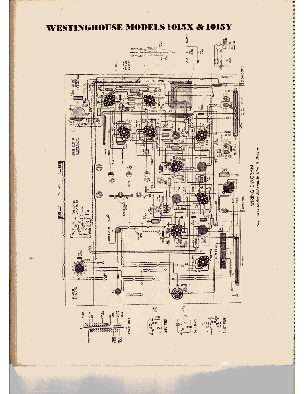
WESTINGHOUSE MODELS 1015X & 1015Y
YELLOW RACK
6a
lr
YELLOW
OSC
10 t51+---YEIIO a
ja
IOS 10 E.
ELI:- THE WY TERMINALS SHOWN
DOTTED ARE lASTENED TO THE
COIL TUBE ONLY
DI 5M
nSnkaM
THRONES 6M6
70 flSTE'1 OF 6116
BLUE 1111
TO
RS C8 I -p MAP
RED ---+10aOCR
181-T2 MAW
7112MMF
BUS-{Q,145 1-121611
1-11
1300
BUS--üQ 144101116
6461400
-SUS 1-41 1-010311
_....10011,17100E
6CAM1ODE
YELL
g,
st
+SWITCH SECTIONS ARE
SHOWN IN MWPOSITION
Ca 6 149
Range Selector Wiring Diagram
I.F. Amplifier:
The intermediate frequency amplifier consists of 2 W.6K7
tubes in a two stage transformer coupled circuit. The windings
of all three I.F. transformers are resonated by fixed capacitors
and are adjusted by moulded magnetite cores, (both primary
and secondary) to tune to 460 Kc. A third winding, L15, in
the first S.F. transformer is placed in aeries with the mein secon-
dary L14 when the fidelity control switch 8-8 is thrown to the
"broad" position (see schematic diagram), thereby increasing
the coupling between the primary and secondary circuits with
consequent broadening of the band width of the I.F. amplifier.
The increase band width of the I.F. amplifier therefore causes
less attenuation of the higher audio modulation side band fre-
quencies, permitting higher fidelity reception.
Second Detector and A.V.C.:
The modulated signal, as obtained from the output of the i -f
system, is detected by one of the diodes of the W -6H6 tube,
Audio frequency secured by this process is paned on to the
control grid of the W -6F5 for amplification before final reproduc-
tion. The d -c voltage, which results from detection of the signal,
is sad for automatic volume control. This voltage, which
develops coron resistor RI4 is applied as automatic control grid
bias to the first detector and i -f tube. through a suitable resistance
filter.The other diode of the W -6H6 tube is used to supply normal
bias to the fret detector and id radiotrons until such time as
the rectified signal voltage is great enough to overcome the
normal hiss voltage and start the automatic volume control
action.A portion of the range selector switch (8.7) is used to change
the minimum bias on the radiotron controlled by the AVC
voltage, so as to reduce the minimum bias and increase the
sensitivity of the receiver on the "medium wave" and "short
wave' position. R.F. Alignment Points
When adjusting the Air Dielectric R.F. trimmers, it is neces-
sary to use a special tool (See H-29644 in parts list) to slacken
the lock nut on the trimmer, previous, to the adjustment, and to
tighten it again after the adjustment. .mother special tool
(See H-29643 in parts list) is available for making the actual
adjustment to the trimotor. The adjustment should be made
upward or downward on the plunger with a twisting motion -
The special tool designed by the Canadian Westinghouse Com-
pany for this purpose is double ended: one end having a pin for
the R.F. adjustments, the other end is a special socket screw
driver for use in making I.F. ad ustments.
1500 AC. 41
5000 KC.
17000 KC. ®
I500 KC. *
5000 KC, 0
17000 KC. ®
1500 KC. OO
5000 KC. ®
14000 KC, ®
[E11lE1ll-1
600. KC
SERIES TRINiN1ER
ANT.
DET.
DSC.
The procedure outlined below should be followed in adjusting
the various trimmer capacitors and molded corn:
WHEN ALIGNING THE R.F. CIRCUITS, THE CHAS-
SIS BOTTOM SHIELD MUST BE IN PLACE ON THE
CHASSIS AND SECURELY FASTENED WITH ALL OF
THE RETAINING SCREWS. IF THE CHASSIS BOTTOM
PLATE IS REMOVED, COIL SHIELDING WILL BE IN-
COMPLETE AND THE R.F. CIRCUIT WILL OSCILLATE.
WHEN ADJUSTING I.F. CORES WITH THE CHASSIS
BOTTOM PLATE REMOVED OR DOING TROUBLE
SHOOTING ON THE CHASSIS, OSCILLATION MAY BE
PREVENTED BY USING A SHORT LENGTH OF WIRE
WITH TWO CLIPS TO CONNECT TOGETHER THE PAR-
TITION SHIELDS BETWEEN THE ANTENNA AND
DETECTOR COILS, AND BETWEEN THE DETECTOR
AND OSCILLATOR COILS.
I.F. ADJUSTMENTS USING CATHODE
RAY EQUIPMENT
1. Set up the Cathode Ray Equipment in the manner re-
commended
mended by the ,manufacturer of the equipment. The fre-
quency modulated oscillator should be connected to the control
grid cap of the W -6K7 second I.F. radiotron (with grid lead in
place), through a .001 Mfd. capacitor. The grounded side of
the test oscillator output should be connected to the receiver
chassis frame. The cathode ray oscillograph vertical terminals
should be connected to points indicated on the radiotron socket
voltage diagram.
2. Place the receiver in operating condition with the fidelity
switch on the tone control in the counter -clockwise or selective
position. The antenna and ground terminal should be short
circuited and if necessary the gang condenser adjusted so that
no stray signals are fed into the I.F. amplifier during the adjust-
ment.Adjust the test oscillator to supply a 460 Kc. audio -modulated
signal. Increase the output of the test oscillator until a deflec-
tion is noticeable on the oscillograph screen. The figures ob-
tained represent several waves of the detected signal, the ampli-
tude of which may be observed as an indication of output. Cause
the wave -image formed to be spread completely across the screen
by adjusting the "Horisontal gain" control. The image should
be synchronized and made to remain motionless by adjusting the
proper oscillograph controls.
3. Adjust the two magnetite core screws of the third I.F.
transformer (see radiotron socket voltage and I.F. terminal
location diagram) to produce maximum vertical deflection of the
Bcillograph image. This adjustment places the transformer in
exact resonance with the 460 Kr. signal.
4. Set up the cathode ray and test oscillator equipment in
the standard manner to provide a frequency modulated signal
and a "double trace" image.
5. Adjust the frequency of the test oscillator until the two
traces move together and overlap with their highest points
exactly coinciding.
6. Now readjust the two magnetite core screws on the third
I.F. transformer so as to cause the two traces on the oscillograph
screen to coincide throughout their lengths and have maximum
amplitude.
7. Without altering the adjustments of the apparatus, shift
the "Ant." output of the test oscillator to the control grid cap
of the W -6K7 first I.F. radiotron (with grid lead in place), through
the .001 mfd. capacitor. Adjust the test oscillator output so
that the amplitude of the image is approximately the same as
used for adjustment (6) above.
8. The two second I.F. transformer magnetite core screws
should then be adjusted so that they cause the forward and re-
verse traces to become coincident throughout their lengths and
have maximum amplitude.
9. Without altering the adjustments of the apparatus, shift
the "Ant." output of the test oscillator to the input of the I.F.
system; i.e., to the grid cap of the W -6L7 first detector (with
grid lead in place) through the .001 mfd. capacitor. Regulate
the test oscillator output so that the amplitude of the oscillograph
image is approximately the same as used for adjustment (8)
above.
10. The two first I.F. transformer magnetite core screws
should then be adjusted so as to cause the forward and reverse
waves to become coincident throughout their lengths and have
maximum amplitude.
11. Note width of oacillographic image at a point which is
50% of maximum amplitude. Turn receiver fidelity control to
extreme clockwise position (high fidelity position). Note width
of oseillographic image at a point which is 50% of maximum
amplitude. Under normal conditions the Tatter measure,nent
should be approximately 60% greater in width than the former
measurement. The image should also appear slightly double
humped. These conditions indicate proper broadening of the
band width of the I.F. amplifier.
12. Turn range selector to "Medium wave" position and
note increase in amplitude. The amplitude should increase
several times. It may he necessary to decrease output of test
oscillator to keep image on screen.
I,F. ADJUSTMENT WITHOUT CATHODE
RAY EQUIPMENT
In most cases provided the I.F. transformers have not been
very badly put out of adjustment, it is possible to secure reason-
ably good results by alignment with a simple 460 K.C. audio
modulated oscillator and standard output indicator. The adjust-
ment should be made in a similar manner described fhr the
cathode ray equipment, but of, course, the I.F. cores should be
adjusted for maximdm output indication only. The adjustments
must be done in the order given and must be done carefully or
unsatisfactory operation of the high fidelity switch will result.
No attempt should be made to adjust the I.F. cores with the high
fidelity switch in the clockwise or "broad" position.
R.F. ADJUSTMENT
Before attetaptiag R.F. alignment itis necessary to set the
pointer in the correct position with relation to the gang con-
denser plates. This is done by setting the pointer to the angle
of the border line of the dial immediately below the 530 K.C.
calibration point, with the gang tuning condenser in full mesh.
"Short -Wave" Trimmer Adjustments
Connect the "ANT" output of the test oscillator to the antenna
terminal of the receiver through a 400 ohm resistor. Set the
receiver range selector switch to its "short wave" position and
its dial pointer to 17000 Kr. Adjust the teat oscillator to 17000
Kr. Adjust oscillator 17000 Kc. trimmer until maximum output
is reached. Two peaks may be found with this circuit. The
peak with minimum capacitance (plunger nearly out) should he
used. Tighten lorknut. Adjust detector 17000 Kc. trimmer
until maximum output is reached while slightly rocking the gang
condenser. Two peaks may be found with this circuit; the peak
with maximum capacitance (plunger nearly in) should be used.
Tighten lockout. Adjust antenna 17000 Kc. trimmer until
maximum output is reached, while slightly rocking the gang
condenser. Two peaks may be found with this circuit; the peak
with maximum capacitance (plunger nearly in) should be used.
Tighten lockout. Check the image frequency by changing the'
receiver dial setting to 16,080 Kc. the image signal should be
received at this position, indicating that the adjustments have
been correctly made. No adjustments should be made while
checking for the image signal.
ADJUST ALL LF TBM6F. MJM.r,SEf}.
TD 46a. AB. S10M iN
¡aDUU S.ifR WDY6SB1,t
®I
617 2a11 / ¡A(7 1.11u ái
©1 IwoO®6Í
MMAA aMR
66ga %M ®.I I_ ®
I-IIM'"
---
Le W. \k
L.®° 1w O® _Í0000 r®OIR-1
524O®t, mI®® oaei_ ó:-te\®®®atsd
F` l-6i-41t ` IF LE ika-6 Sa.IE i 6M616,a---I
IÓw. ®OlY iÍÑM o®
^Qll
617617
BOTTOM OCAS MOSS 'coma 15111113-aY RIeEEN
INK IERMNSL Am 11151115
Radiotron Socket Voltages and I.F. Trimmer Locations
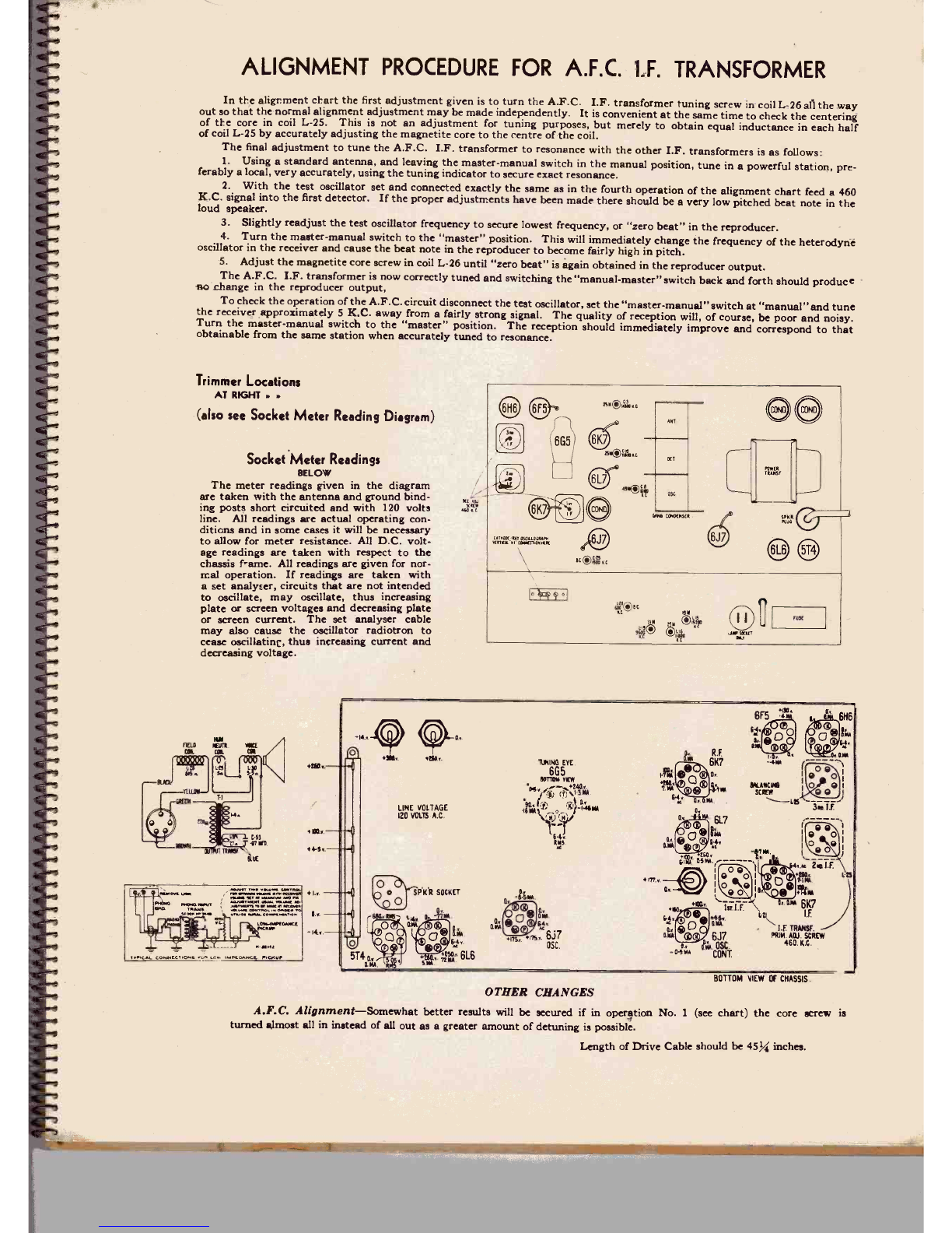
The meter readings given inthe diagram wetaken with the
re and and bandies posts hort circuited nd with 1010 vats
antennaAll reading* .re actual perating conditions sod In sums cars
r'll be nec.ry to allow for meter resistance. All D.C. voltage
ead diallowings
are taken with respect to the chassis triune. All «tllngs .re
-Iit -14.. a.
nnn
given for normal operation- If readings are taken with a set umbrae.
circuit. that are not intended to wcA,ate. may smote. thusincrements
r .mean vmemar and derre.aing plate st rreen .solemn The
aalyrt able may aim uur dedecreasing rolls., to cease
oscillating. en`,. increasing current .m aerre..ma ynlwe.
In some cases the socket contacts of "blank" radiotron pins are used as terminals for chassis parts. The voltages shown above
on such contacts are circuit voltages, not radiotron voltages.

I
CANADIAN WESTINGHOUSE MODELS 1029X and 1029Y
ar
1st no,
o¡w¡
o
0
6LT
In OCT rrl
PO°OO
Idi
assera
IIM.we Os..OUA n«e.
ENT
Inca
657
oO.vO ten
O-41--_.lor
: CStee
irle irle
O.u0
se0
13
6N6
Y. AVDrt
VC
O
5T4
secr.
Opp
Ol ooco- ./
O
*FS
AUDIO aR Ai
rn<CO ,
í&i°s
n ZS
ti
wzm
Ta er,&a
WHEN RECEIVER IS CORRECTLY TUNED IN
I.F. signal devel-
oped here is 460 k.c.
and this voltage
t) is applied across
points A and B.
.A
(DVoltageai:iááNRaa
o.11. awn d volt,
He &paliad across
point.A.Band volt.
oree ,poled acrom
suer lulydLES.
Voltage actna a.
R} W
diode No.
M voltage
vgeanarinwn
half or cod Lxs.
1
Schematic Circuit Diagram
OJ The croon M L25,
r.x+and C33 to s uned
In 50 K.C. and is in
resonance with the in.
(lured voltage.
The induced voltye
a... hallo( L25
batten equeach phase
relation with respect to
the voltage appliedl-
rectified óes n.
egn.. RI2 and
equal npxts.
the A. C. volt..
nanc to ground ú
R10. 04.
A.F.C. moos. 1.0 MEG
a
tnC.33. `s üytwC3K.
IM Vy-200
MMF. R.li
DIODE OF W6H6 g10000
¡\
L-278
I.F. signal devel-
oped here is 465 k.c.
and this voltage
is applied across
points A and B
E
0.11.
451070 7
OFF °ON
Sor
cx.
eTO
Rau. VOL^UME
2211:0u Cgl. CONT.
01--10D
R 15. O$C
22 CONTROL
MF MEG. al WAGS
GRIDTO
WR.F DET.
AND IF.
GRID BIAS
O2 The circuit of 1.20, 1.26 and C33 is
not in rmonance with the induced
voltage. This< canna the voltage atm..the
upper half of L25 to become more
nearly in phase with the voltage ap-
plied emcee A and B and increases the
rectified voltage acre. R13. It also
the voltage across the lower half
of L25 to become further out of phase
with the voltage applied across A ant
WHEN RECEIVER IS INCORRECTLY TUNED IN (5 K.C. HIGH) B and deºeaas the rectified voltage
scree. RI2. Consequently the result-
ant voltage from Ctogrotmdi.ptaitive.
R -I1.
10
MEG. R-27.
6L6
OUTPUT
1.19
(Arid of control tube is
connected to a point on
the oscillator tuned cir-
cuit and the plate is con-
nected to the "high" end of
the oscillator tuned circuit.
The phase relations are
such that the amplified
voltage developed on the
plate has the same effect
as an inductance in parallel
with the tuned circuit.
C14.tA MMF
R-7.
1 33(02 ~if12
y...,211. MMF.
MÍEF
15V. QThis positive voltage de-
creases the bias on the control
tube and increases the am-
plification. This has the
effect of increasing the equi-
valent inductance seroso the
oscillator tuned circuit and
consequently lowers the os-
cillator frequency so as to
correct the error in dial set-
ting.
DETAIL OF AUTOMATIC FREQUENCY CONTROL CIRCUIT
gCa1.
SM MMF.
C10.
11-SqMMF.
GS2 C11
470 MMF. 111MMF. To
OS:..
53 GRID
When the receiver is tuned too low, the A -Ft. voltage becomes negative, and results in an opposite corrective effect on the
oscillator frequency.
It will be noted that the automatic frequency control is applied to the broadcast band only and that two *witches 8-4 and 3-7
are provided to short circuit the automatic frequency control voltage when its presence is not desired. One switch S-7 is mounted
so that by an inward motion while turning tfie station selector the A.F.C. voltage is removed, thus permitting the station to be
tuned without a "dragging" effect that would otherwise exist if the operator attempted to tune past a powerful station to pick up
weaker one.
CNIS MED.
111v.
4

rJytllllll111111.1J11.111JJJJJJJi1.14.14111111.1.111.1.11114.tIrJJJJa.1aJJ3111aaJ1a4i1raaaJaai1aia41iilr
TUNING
INDICATOR SOCKET
CABLE ASSEMBLY
BASS
TONE
CONTROL
AND
POWER
SWITCH
BE
ó
LAMP SOCKET
ONLY
TREBLE TONE CONTROL
ANT. COILS
AND
SWITCH RE
GRID
RF COILS
AND
SWITCH
PIEsi
-L-vEllow-
OSC. COILS
AND
SWITCH PIE
51 RE
RANGE SWITCH
CONTROL SHAFT
m
19M 25 MI
oo
AUTO FRED sA
CONTROL
AUTO FREQ
SW:TCH
31 MI 49M BC
o
ll
Ow
_W
VOLUME
CONTROL
2.5 MEG. TOTAL BROWN
GRID
D
2_
r__D_
PRONO TERMINAL-'
8OARD
POWER
CABLE
Chassis Wiring Diagram
I10MMF
ET'ANSFORMER
2ND
ITRANSFORMER
1sT.
ITRANSFORMER

ALIGNMENT PROCEDURE
There are various alignment trimmers provided in the detector
and oscillator coil tuned circuits. The i -f transformer adjustments
are made by means of screws attached to molded magnetite cores.
411 of these circuits have been accurately adjusted during manu-
facture and should remain properly aligned unless affected by
abnormal conditions or altered during servicing. Loss of sens-
itivity, improper tone quality, and poor selectivity are the usual
indications of improper alignment.
The correct performance of this receiver can only be obtained
when the aligning has been done with adequate and reliable
apparatus. It is not necessary to use a frequency modulated
oscillator and cathode ray oscillograph to align this receiver.
Those service men that have this equipment will probably prefer
to use it and for their convenience we have indicated on the
trimmer location diagram the proper connection point for the
cathode ray vertical amplifier input terminal.
A test oscillator is required as a source of the specified align-
ment frequencies. Visual indication of receiver output during the
adjustment is necessary and should be accomplished by the use
of an indicator or meter.
The procedure outlined below should be followed in adjusting
the various trimmer capacitors and molded cores:
Calibrate the tuning dial by adjusting pointer to the low
frequency end of scale with gang condenser plates fully meshed.
The pointer may be adjusted along the phosphor bronze drive
cable by slackening the stud which secures the glider to the phos-
phor bronze drive cable.
Perform alignment in proper order as shown by the accom-
panying chart, starting with No. 1, and following all operations
across, then No. 2, etc. The chassis bottom shield must be
securely in place when making R.F. adjustments. Adjustment
locations and fequencies are shown on a sticker fastened to the
bottom side of the chassis shield. These trimmer locations are
also shown in one of the accompanying illustrations.
Connect the "low" output terminal of the test oscillator to the
receiver chassis for all alignment operations. Regulate the output
of the test oscillator so that minimum signal is applied to the
receiver to obtain an observable output indication. This will
avoid a -v -c action.
The term "Dummy antenna" means the device which must be
connected between the "high" test oscillator output terminal and
the point of connection to the receiver in order to obtain ideal
alignment. "No signal, 550-750 kc." means that the receiver
should be tuned to a point between 550 and 750 kc. where no
signal or interfrence is received from a station or the receiver
(heterodyne) oscillator.
The term "Rock Through" indicates that the receiver station
selector should be rocked back and forth while making the
indicated adjustment. The adjustment and rocking should be
continued until the combined action results in the maximum
deflection on the output meter.
When adjusting oscillator circuits that nave both series and
shunt trimmers it is good practice to repeat the adjustment on
the oscillator shunt trimmer after making the adjustment on the
oscillator series trimmer.
When calibrating the short wave "spread" bands (see operat-
ions 6, 9, 10 and 11 in the Alignment Chart), it is necessary to
have a very accurate source of test signal. As there are no service
oscillators available at present with sufficient accuracy for this
calibration adjustment, it is recommended that the respective
adjustments to L-16, L-17, L-15 and C-8 be made while listening
to a short wave broadcast station of known frequency, approxim-
ately in the middle of the band being calibrated. Operations
7 and 8 may be performed after operation 6 by setting the re-
ceiver to 11,800 kc. and tuning the test oscillator to the receiver
PRECAUTIONARY LEAD DRESS-(1) All bare bus leads
adjacent to the R.F. coils or Range Selector Switch should be
as short and direct as possible.
(2) All insulated leads adjacent to the R.F. coils should be
dressed away from the coils.
(3) Heater leads should be tightly twisted together and dressed
away from grid leads of audio tubes to avoid hum pick-up.
(4) Leads connected to phonograph pick-up terminal should
be tightly twisted together and dressed close to chassis frame.
(5) Power output stage grid leads should be dressed away from
the high voltage secondary winding leads of power transformer t'.
avoid hum pick-up.
ALIGNMENT CHART
Order of
Align-
ment Connection
To Receiver Test Oscillator
Dummy
Antenna Frequency
Setting Receiver
Dial and
Range Setting
Master-
Manual Sw.
Position Circuit
To Adjust Adjust-
ment
Symbols Adjust to
Obtain
1. Turn this screw all the way out. A.F.C. I.F. L 26
2. Check with mechanic's scale. This screw should protrude exactly % inch. A.F.C. I.F. L 25
3W -6K7 I.F.
Grid Cap .001 Mfd. 460 kc. No signal
550-750 kc. Manual 2nd. I.F.
Transf. L23, L24 Max. (Peak)
4W -6L7
First Det. .001 Mfd. 460 kc. No Signal
550-750 kc. Manual 1st. I.F.
Transf. L21, L22 Max.(Peak)
5W -6L7
First Det. .001 Mfd. 460 kc. No Signal
550-750 kc. Manual .. 2nd. I.F.
Transf. L23, L24 Max (Peak)
6Ant. Term. 400 ohms 11,800 kc. 11,800 kc. Manual Osc. 25M. L16 Max (Peak )t
7Ant. Term. 400 ohms 11,800 kc. 11,800 kc. Manual Det. 25M. C19 Max (Peak)**
8Ant. Term. 400 ohms 11,800 kc. 11,800 kc. Manual Ant. 25M. C3 Max (Peak)**
9Ant. Term. 400 ohms 9,600 kc. 9,600 kc. Manual Osc. 31M. L17 Max (Peak )f
10 Ant. Term. 400 ohms 15,200 kc. 15,200 kc. Manual Osc. 19M. L15 Max (Peak )t
11 Ant. Term. 400 ohms 6,100 kc. 6,100 kc. Manual Ose. 49M. C8 Max (Peak)*
12 Ant. Term. 200 mmfd. 1,500 kc. 1,500 kc. Manual B.C. H.F. Osc. C25 Max (Peak)**
13 Ant. Term. 200 mmfd. 600 kc. Rock Through
600 kc. Manual B.C. L.F. Ose. L20 Max (Peak)
14 Repeat 12
15 Repeat 13
16 Repeat 12
17 See instructions below for A.F.C. Alignment L26.
* If two peaks obtainable use higher capacity setting. t If two peaks obtainable use lower inductance setting (screw fur-
** If two peaks obtainable use lower capacity setting. ther out).

ALIGNMENT PROCEDURE FOR A.F.C. I.F. TRANSFORMER
In the alignment chart the first adjustment given is to turn the A.F.C. I.F. transformer tuning screw in coil L-26 all the way
out so that the normal alignment adjustment may be made independently. It is convenient at the same time to check the centering
of the core in coil L-25. This is not an adjustment for tuning purposes, but merely to obtain equal inductance in each half
of coil L-25 by accurately adjusting the magnetite core to the centre of the coil.
The final adjustment to tune the A.F.C. I.F. transformer to resonance with the other I.F. transformers is as follows:
1. Using a standard antenna, and leaving the master -manual switch in the manual position, tune in a powerful station, pre-
ferably a local, very accurately, using the tuning indicator to secure exact resonance.
2. With the test oscillator set and connected exactly the same as in the fourth operation of the alignment chart feed a 460
K.C. signal into the first detector. If the proper adjustments have been made there should be a very low pitched beat note in the
loud speaker.
3. Slightly readjust the test oscillator frequency to secure lowest frequency, or "zero beat" in the reproducer.
4. Turn the master -manual switch to the "master" position. This will immediately change the frequency of the heterodyne
oscillator in the receiver and cause the beat note in the reproducer to become fairly high in pitch.
5. Adjust the magnetite core screw in coil L-26 until "zero beat" is again obtained in the reproducer output.
The A.F.C. I.F. transformer is now correctly tuned and switching the "manual-master"switch back and forth should produce
no change in the reproducer output,
To check the operation of the A.F.C. circuit disconnect the test oscillator, set the "master -manual" switch at "manual" and tune
the receiver approximately 5 K,C. away from a fairly strong signal. The quality of reception will, of course, be poor and noisy.
Turn the master -manual switch to the "master" position. The reception should immediately improve and correspond to that
obtainable from the same station when accurately tuned to resonance.
Trimmer Locations
AT RIGHT . .
(also see Socket Meter Reading Diagram)
Socket Meter Readings
BELOW
The meter readings given in the diagram
are taken with the antenna and ground bind-
ing posts short circuited and with 120 volts
line. All readings are actual operating con-
ditions and in some cases it will be necessary
to allow for meter resistance. All D.C. volt-
age readings are taken with respect to the
chassis fame. All readings are given for nor-
mal operation. If readings are taken with
a set analyser, circuits that are not intended
to oscillate, may oscillate, thus increasing
plate or screen voltages and decreasing plate
or screen current. The set analyser cable
may also cause the oscillator radiotron to
cease oscillating, thus increasing current and
decreasing voltage.
6G5)
EATNaUarlxaNwlN
NITI4'Mi WORM Ntlt
IE®
ANT
AT
Ott
441. CONDENSER
LOt10. CONO
im eE NN
]IN nN OiP5e
Ot4
,,E,IE
Tux
+ sr.. .ao,.
o
LINE VOLTAGE
120 VOLTS A.C.
OSPKR SOCKET
0606
5T4 a,aw.
(i) 00.
aeo.'asw' 6L6
aN
a..aw
1
-F/w
cr ----
(001 o o i
IGf
1po
K 2m1.F.
.1LO
:Ikiw
6K7
4.1
19/(76,
p/®U - `I.F. TiGNSi.
®-
aw119 6J7 rxw AEU
-a'w, .. 460. K.C.
CONT.
BOTTOM VIEW Or CHASSIS
OTHER CHANGES
A.F.C. Alignment-Somewhat better results will be secured if in operation No. 1 (see chart) the core screw is
turned almost all in instead of all out as a greater amount of detuning is possible.
Length of Drive Cable should be 455í inches.

SHORT WAVE CALIBRATION
WESTINGHOUSE MODELS 1029-X, 1029-Y AND 1230-X
We have found that, during shipment, it is possible for the oscillator control grid lead in these receivers
to shift sufficiently to throw the short wave dial scales somewhat out of calibration. When this occurs, the
calibration on all short wave bands will usually be found to have shifted in the same direction, that is, all four
dial scales will be high or all four dial scales will be low.
If such a condition is found, it will be a simple matter to correct it by rotating the oscillator control
grid clip so as to change the position of the flexible lead, checking the calibration on the short wave bands while
this is being done until the calibration is accurate within 5 K.C.
DO NOT LOOSEN THE CHASSIS MOUNTING BOLTS
ON WESTINGHOUSE MODEL 1230-X
Contrary to instructions attached to radio receivers from early production, these chassis mounting bolts
should not be loosened, as due to the slope of the chassis shelf, the chassis may sag on the rubber cushion
sufficiently to interfere with proper operation of the pushbuttons. When it is necessary to remove a chassis
for servicing, the service man should be careful to replace the chassis as far forward as possible in the cábinet
and hold it in place while tightening the chassis mounting bolts and checking the pushbutton operation.
INSTRUCT YOUR CUSTOMERS IN THE PROPER OPERATION OF THE
REMOTE CONTROL USED WITH MODEL 1230-X
Lack of proper instructions at the time of sale may result in unnecessary service calls; for instance, the
customer may call up and say that a Model 1230-X is dead; "he has tried all the controls and can't hear a
sound." The trouble may only be that the toggle switch on the remote control has been turned to the "Off"
position. The customer may forget this and attempt to operate the set the next time from the front of the
cabinet and wonder why no sound is heard.
If two or more buttons on the remote control are left pressed down and then the customer attempts
to operate the receiver by the buttons on the front of the cabinet, the tuning motor will operate continuously
if any of the buttons on the front of the cabinet corresponding to the down button on the remote control are
pressed. A similar result will be obtained if two or more buttons on the front of the cabinet are left pressed
down and the customer attempts to operate the receiver by remote control.
Another possible condition is as follows: Assume that the controls have been correctly set and a station,
WJR, tuned in by the remote control. Customer may leave control set at this position and turn the operating
switch off; the next time he operates the receiver he may attempt to do so by the pushbuttons on the front
panel, neglecting to turn the "Manual, Button, Remote, Master" control to the "Button" position.
If the panel button also happens to be pressed for the same station, WJR, and another button is then
pressed, there may be an instant when the switch corresponding to the WJR panel button and the other panel
button switch are both making contact. This contact may last long enough to start the motor going but the
tuning mechanism will continue until WJR is tuned in again instead of the station the customer is trying to
get incorrectly.
These conditions will be perfectly understood by a study of the wiring diagram of the electric tuning
and being familiar with them, you may be able to save yourself making unnecessary service calls by explaining
to the customer over the 'phone the proper method of operation.
the band.
anal lugs
tight but
place the
served on
of one of
OSCILLATOR INOPERATIVE ON STANDARD BROADCAST BAND
OF WESTINGHOUSE MODEL 1230%
This condition may extend over the whole band or only over the lower half of
A possible cause is a poor contact between the aluminum post and the term -
of one of the electrolytic condensers. This lug may appear to be clamped
an imperfect contact may exist due to a film of resin. The remedy is to re -
electrolytic or remove it and repair it. This condition has only been ob-
Westinghouse Model 1230X but may show up on other receivers.
CALIBRATION SHIFT ON STANDARD BROADCAST BAND OR
49 METER BAND OF WESTINGHOUSE MODEL 1029 and 1230
This may be due to an imperfect contact of the wire lead to the moulded frame
the air dielectric trimmers. This condition may be corrected by soldering.

WESTINGHOUSE MODEL 1230X
ELECTRIC TUNING
Principle of Operation
The electric tuning mechanism consists essentially of a
quick engaging and dis-engaging reversible electric motor,
tuning condenser driving gear train, and eight mechanically
interlocked (pushing one button releases all others) station
selector push buttons respectively wired to eight adjustable
station selector contactor discs (each with a motor stopping
insulated segment) inr,inted on a drum which is direct -coupled
to the gang tuning condenser shaft. The arrangement permits any
one of eight pre -determined stations to be electrically tuned
in by merely touching the correct push button.
The operation may be more readily understood by ret -
erence to figures 1, 3, and 6. When the motor is not ener-
gized, the armature is pushed to the rear or slightly out of the
magnetic center by tension of contact spring "C" and the motor
shaft is dis-engaged from the driving gear train. Pressing in any
one of the eight push buttons will complete the motor circuit
through a station selector contactor disc, assuming that the A.F.C.
and Motor Control is in "Electric" position and that the insulated
segment in the contactor disc is not opposite its contactor. As
the motor starts, the armature will be drawn forward, due to
solenoid action, and the pin "F" on the end of its shaft will
engage the arm "G" on the small main pinion gear, thereby
driving the tuning mechanism. At the same time contact springs
"E" and "D" (S11) will be grounded, causing suppression of audio
amplification and automatic frequency control during the tun-
ing cycle. The motor will contunue to operate until the in-
sulated segment in the selector disc breaks the motor circuit,
whereupon spring "C" will instantly dis-engage the motor pin
"F" from the arm "G" on the small pinion driving gear and
open contacts "E" and "D". Pushing another button will
cause the above mentioned cycle to be repeated except that
the motor will be interrupted by the insulated segment on a
corresponding disc. The discs are individually adjustable on
a drum mechanism, providing a choice of eight "Electric Tuned"
stations. The arrangement of the motor is such that its rotation
will continue in the same direction regardless of the number of
"Electric" tuning cycles until the tuning condenser approches
either full out or full in of mesh whereupon lever "H" trips switch
S9 whichr everses the direction of rotation. A throw -out idler gear
is link -coupled to the A. F. C. and Motor control to dis-
connect the motor drive gear train when the control is thrown
to "Manual" or "Master" position.
Mechanism Adjustments
The electric tuning mechanism is designed to be as simple in
construction and as fool proof in operation as is possible. In
order to maintain the accurate results possible with this device
care must be taken in effecting any repairs or adjustments.
Reference should be made to figure 5 and the following:
A -F -C and A -F Amplification Suppression Switches. -
This switch assembly is located on the motor bracket and
closes due to solenoid action of motor armature. The tension
of the long contact spring "C" is important in bringing about
quick dis-engagement of the motor and in permitting the motor
to pull into mesh with the drive mechanism. Normal adjustment
is attained when the short springs "D" and "E" are aligned
exactly straight with contact points separated approximately
1/32 of an inch and with the spring "C" spaced approximately
7/32 of an inch from spring "D" at the point of contact. If
necessary, in order to obtain positive pull -in and quick dis-
engagement of the motor, the tension of spring "C" should be
increased or decreased by bending. This action should be checked
with the front of the chassis raised two inches higher than the
rear. Contacts of the switch must be kept clean. Crocus cloth
or a relay burnisher may be used for this purpose.
On all but a few of the first production of 60 cycle motors an
additional adjustment is possible to secure positive pull -in of the
motor. A flat phosphor bronze spring is mounted at the rear of
the motor and exerts a pressure (which may be varied by bending)
on the end of the motor shaft.
A relay bending tool equivalent to the Automatic Electric
Company, Chicago, Illionis, tool No. 7066, will be found handy
in bending the fingers of the switch for proper adjustment. This
tension adjustment may have to be changed to secure proper
operation on low line voltages; the lower the voltage the less
should be the tension of the switch finger against the rotor shaft.
Motor Reversing Switch.-It is necessary to automatically
stop and reverse the drive motor before the tuning condenser
reaches the end of its travel. Approximately 175 degrees of
sweep it required, and the reversal must take place above 1,700
kc and below 540 kc but not too near the limits of the scale.
The coupling between the station selector drum and the tuning
condenser shaft should be attached so that the reversing switch
trip lever "H" is exactly vertical when the condenser is full -out
of mesh. There should be 1/32 of an inch clearance between
the end of the condenser shaft and the selector drum shaft.
While the trip lever is in this position the reversing switch bracket
should be adjusted by means of its elongated mounting holes
until the switch pin "I" just lightly touches trip lever "H."
Main Pinion Gear.-Clearance between the small high-
speed pinion gear "E" and the intermediate gear "K" deter-
mines the amount of mechanical noise produced. Correct
adjustment will give approximately 1/32 of an inch move-
ment of back lash at the end of pinion arm "G" when gear
"K" is held stationary. Arm "G" must also be adjusted for
correct mesh with motor shaft drive pin "F". With the motor
shaft completely forward and pinion "E" tight against its front
bearing, the pinion mounting stud "J" should be adjusted so
that pin "F" meshes its full thickness with the rotating arm
"G." An increase of this mesh will increase over travel on
tuning while a decrease of mesh will decrease the over travel.
The elongated hole in the front bracket allows sufficient move-
ment of the mounting stud "J" to permit above mentioned
gear mesh adjustment.
A.F.C. and Motor Control.-(1) Link and lever adjustment.
By loosening the set screws holding the link lever on the switch
shaft, an adjustment can be obtained so that the throwout gear
(M) has at least 1/16" clearance with respect to intermediate
gear (L) when the control is in either the Manual or Master
position.
(2) Throw -out Gear Adjustment-To obtain smooth opera-
tion on "Electric" or "Remote" positions it is important
that the proper clearance is maintained between the throw -out
gear "M" and the intermediate gear "L." With the control
thrown to "Remote" position, adjust the mesh between these
gears by means of the eccentric screw "O" and lock nut "P"
on the throw -out gear bracket "MM" until there is approximat-
ely 1/64 of an inch backlash of gear "L" when gear "M" is held
stationary.
3. If there is a tendency for the throw -out gear "M" to come
out of mesh in either direction of rotation, this may be corrected
by increasing the tension on spring "N" or replacing this spring
or by relieving any binding of the lever to which the throw -out
gear is attached. Binding of this lever may occur at the bearing
on the tuning shaft assembly. The bearing of the lever should
be carefully washed out with Carbona of equivalent, and re -oiled
plentifully. Work the lever back and forth while cleaning and
oiling so that any foreign particles will be removed.
Replacing Gear Train.-It should be replaced by sliding
anti -backlash gear "R" on condenser shaft apart so that compres-
sion amounting to one tooth on the gear is obtained in the springs.
Adjust mesh of gear "R" with pinion gear "U" on vernier shaft
before tightening screws "S" so that smooth tuning is obtained
throughout the range.
Motor Alignment.-The motor shaft must be exactly
aligned with the axis of the pinion gear with which it engages.
This may be adjusted by loosening the mounting screws "V" of
the motor and aligning shaft by sight. Correct alignment may
be tested by slowly rotating motor and observing the relation
between the pin "F" of the motor shaft and the arm "G" on the
pinion. The relation of the two should remain the same through-
out the revolution. Additional movement for adjustment may
be obtained by the motor bracket screws "W" if necessary.

ECCENTRIC
ADJUSTING
SCREW
MIS. STUD
FOR
SPRING M
K
BACKLASH WITH
6EAR-I STATIONARY
GEAR10
INTERMEDIATE
GE AR'2
MOTOR SHAFT MHIN PINION GENR'E' AND
ENGAGING PIN HAM'C
MAIN
PINION
GEAR E
NTERMEDIATE
GERR . 3
DRIVE GEAR
ANO SET SCREWS
REAR VIEW
,,SPRING 'N
`LINK
LINK HNC, LEVER RSSEMBLY
FRONT VIEW
r, '+
MOTOR SHAFT
FULL FOWRRD
I ,, DRIVE GEAR -ARM
GEAR STUD ADJUSTING
RI NUTS
i;jI INTERMEDIATE
j »ERR
;. ANT2I-BACKLASH
1SCISSORS GEAR
Ill ON TUNING CONO.
-I SHAFT
-I,1 I-
III TUNING CONDENSER
VERNIER DRIVE
iII SHAFT AND PINION
EAR
INTERMEDIATE
GERRE
C SLOT IN
CHASSIS APRON
DRIVE GEARARM J"
MOUNTING STUD
SIDE VIEW
LEVER ADJUSTMENT
SCREWS
"R -R" DRIVE GERR TRRIN RSSEMBLY
TYPE 2
RIVETED
CONTACTSCONTACT
STRIP RDJ.
NUTS
CONTACT
RDJ. SCREWS
CONTACT ASSEMBLIES (BOTTOM VIEW)
TYPE 1
ADJUSTABLE
CONTACTS
SELECTOR ADJ
REY
ADJUST CONTACTS
'TO STRAIGHT EDGE
STATION SELECTOR
IDRUM D1515
INSULATED
SEGMENT
CONTACT
ADJUSTING KEY
RECEPTACLE
STATION ADJ.
STRIP
KEY RDJ.
SLOT
MOTOR SPRING
(OA GO- OHO
o
OAOT0405O+OsOEOI
MOTOR -BRAE HE r
SCREWS 'W"
MOTOR MOUNTING
SCREWS 'V''
STAT ON SELECTOR
DRUM COUPLING
ADJLSTING SCREWS
SELECTOR
DRUM SHAFT
FRAME \--
SELECOR
DRUM BEARING 'Xe
ADJUSTING SCREWS
DRUM BEARING "Y
ADJUSTING PLATE
"B -B" STATION SELECTOR
DRUM BEARING.REVERSING SWITCH
ADJUSTING NUTS
TX -560926
©RCA MFG. GO.,INC.
CONTACT ADJUSTED
__,TO CENTER OF INSULATED
SEGMENT WITH KEY IN SLOT
"D -D" STATION SELECTOR DRUM CONTRCT RDJUSTMENTS
STATION SELECTOR
DRUM REAR SEARING"X"
ADJUSTING SCREWS
POINTER
SLIDER
POINTER
POINTER ADJUSTING
SCREW
LAMPING
STUD
A5531.
SPRING
DRJVE CORD
FINISH
HERE
TART
HERE
TUNING COND
SHAFT
CAUTION- ADJUST INDICATOR DRUM ON
SHAFT SO THAT 'G, SLOT IS CLEAR
OF TUNING CONDENSER
DRIVE SHAFT FOR CONDENSER FULL -
OUT ANO FULL -IN MESH POSITIONS.
TUNING CONDENSER
INDICATOR DRIVE
BRACKET ROTATED COUNTER
CLOCK 'ISE TILL THIS SPACE
TO WITH LSHAFT
REAR TEN
RET IGHT EN
BRACKET
CONTACT BRACKET ADJUSTING
ADJUSTING SCREWS SCRE 5
MOTOR
3 AFT
CONTACT
BRACKET ROTATED
ExTREME CLOCKWISE
Su
ADJUSTMENT OF ADJUSTMENT OF
SPRING BRACKET
"F -F" A.F.C. AND A.F. AMPLIFICA T ION
SUPPRESSION SWITCHES.
'Y'CONTACT ST IP
ADJUSTING NUTS
MOTOR REVERSING SWITCH
PINK' SHOULD 5.ICHTLY TOUCH
TRIP LEVER .1.1 WHEN TUNING
CONDENSER IS FULL OUT OF
MESH.
MOTOR REVERSING
SWITCH
INSULATED SEGMENT
ADJUST HUB RND RRM ON REAR
OF TUNING CONDENSER 50 THIS
LEVER IS VERTICAL WHEN TUN-
ING CONDENSER IS FULL OUT OF
MESH.
"C -C" MOTOR REVERSING SWITCH ADJUSTMENT.
Figure 5- ELECTRIC TUNING MECHANISM ADJUSTMENTS
4 r t s! It or r' .f nW al Nmi at 4 IV ' g a 4 4 l 4 9' A'. 4 4.a n" Ale .a re - r r.- u a, s. ,- s, ........ --

Station Selector Drum. --(1) Bearing Adjustment --The
selector drum may be removed by unscrewing the two bear-
ing adjusting screws "X" on the front and rear bearings and
sliding shaft out of slots on frame. To replace drum, the reverse
procedure should be followed holding bearing adjusting plates
"Y" firmly against the shaft and tightening adjusting screws.
(2) Contact adjustment-Two types of contact strips are used
They are designated on figure 5, as types 1 and 2, on which the
individual contacts are respectively adjustable and fixed. In
type 1, the individual contacts should be adjusted by setting
the end contact springs near the mid -position of their travel
and aligning the remaining springs to them by means of a straight
edge. Either type of contact strip should be adjusted to the
selector drum by placing two selector adjusting keys in the
station adjustment strip, positions 1 and 8, loosening contact
strip adjusting nuts "Z" and shifting the contact strip until
the end contacts are exactly centered on the respective disc
insulating segments. More accurate adjustment may be
made by silhouetting the point of contact with a piece of
white paper held behind the contact. Adjustment will be
facilitated by removing complete assembly rear of tuning
condenser by unscrewing the three mounting screws. Contacts
and discs must be kept free of dirt, filings, and other extran-
eous matter.
Arcing at the insulating segments of the selector discs
will produce a bad interference during "Electric" tuning but which
will not be present during "Manual" tuning The condition will
in most cases be due to an accumulation of metallic dust, or
graphite grease on the discs. Thorough cleaning of the discs
with a cloth and cleaning fluid, polishing with crocus cloth and
careful re -lubrication will eliminate the trouble.
Lubrication.-The dial pointer slide should be greased
with petrolatum. This same lubrication should be applied
lightly to all gear faces of the drive mechanism and sparingly
with a cloth to the station selector discs. Any good house-
hold oil, such as "3 -IN -ONE," is suitable for the motor shaft
bearings. A light grade of engine oil should be used for all gear
bearings, Medium viscosity engine oil, similar to "PYROIL"
(B), should be applied between the thrust washers on the motor
shaft. "CASTORDAG," a mixture of graphite and castor oil,
is recommended for use at the selector drum end -bearing slots
and at the bearings of cable pulleys.
Motor slips in and out of Mesh and appears to be
overloaded.
In the foregoing paragraphs are described several adjustments
and conditions, which if abnormal, will result in failure of the
motor to operate properly. It will also be obvious that any
friction condition that causes the motor to become overloaded
may also result in the motor dropping out of mesh. Sorne of
these other causes are:
1. Friction between the large tuning knob and the cabinet
or the inner knob.
2. The slider of the dial pointer may be hitting a burr on its
guide channel.
3. Condenser rotor contact springs may be too tight.
Station Adjustment
Any 8 stations may be controlled by the Buttons. Cut
labels for the particular station desired and insert the labels
in the Buttons with the small celluloid "windows" in front.
Turn the power on ánd proceed to set up the "electric" tuning
as follows:
1. Set Range Selector to "Broadcast."
2. Turn A.F.C. and Motor control to Button.
3. Turn Fidelity control counter -clockwise.
4. Press push button No. 1 and wait until station pointer
comes to rest.
5. Turn the A.F.C. and Motor control to "Manual."
6. Remove adjusting key from receptacle on top of station
selector drum mechanism.
7. Insert key in position marked, "1" in station adjust-
ment strip and push the key all the way down to properly
fit in slot in disc.
8. Tune the receiver very carefully by means of the manual
tuning knob and the "Magic Eye," to station chosen
for No. 1.
9. Remove key.
10. Turn the A.F.C. and Motor control to "Button."
Button No. 1is now properly set for "Electric" tuning
Proceed similarly for the other seven push buttons, matching
each station on the dial with the same number on the station
adjustment strip. Repeat the above steps but place the key
respectively in positions 2, 3, 4, etc., and in each case tune to
the proper station. Now when you press a button the desired
station will be tuned in electrically.
It is possible to set the mechanism to tune in electrically short
wave stations as well as standard broadcast stations but the same
stability of adjustment cannot be expected as there is no A.F.C.
action on the short wave bands.
Ordinarily, stations separated by 10 kc may be set up and
tuned electrically. It is not very wise however, to attempt to set
up a weak station for electric tuning on a channel adjacent to a
strong station, unless the station is of sufficient strength to
actuate the A.F.C.
If two Buttons ale pressed simultaneously, they will both
lock in position, the motor will never become open circuited at
the selector drum and the motor may continue to operate as
long as the radio is turned on. Pressing any one other Button
will release the locked Buttons and permit normal pushbutton
operation.
If all eight Buttons should be locked in position simultan-
eously (this is a possible but unlikely occurance), the same
thing will happen but normal operation may be restored by ex-
erting strong pressure on Button No. 8.
Armchair Control
When a S No. H-38205 Remote Control is attached to the re -
ceiver as shown in Figure 6, it duplicates the action of the push-
buttons on the front panel when the A.F.C. and Motor Control
is turned to the "remote" position. A S.P.S.T. switch which is
Reference to Figure 6 will show that buttons No. 4 and No. s
on the arm chair control are marked with an asterisk. If due
to experimenting on part of the owner, all eight buttons on the
control are simultaneously pressed in position, the condenser
drive motor will operate back and forth continuously as long as
the radio operating switch is on and the A.F.C. and Motor con-
trol is in the "remote" position, unless either button No. 4 o:
button No. 5 is pressed firmly, allowing of all the other buttons
to release.
mounted on the Remote Control permits the operator to open
circuit the reproducer voice coil without walking over to the
radio receiver.
Extra lengths of control cable may be used if it is desired
to have the Remote Control at a greater distance. This should
not be done, however, where, the power line voltage is low as the
added voltage drop in the cable circuit will reduce the power of
the drive motor and prevent correct operation.

CZ
330 M60
O
6RKF7
Ci3
b20N6
L21
6K7
r ( 1sT 1.F
01-21
03e7
O32
0.4í L400
1. O.inO ST
'-oBOAo f.SNW[[I C
izo0
LaosEROM RE
54 RE
3XIDK0INEAGLE
000
co161Nf RV INO
C-17@--)
1035 MNr
4-040 >
O
20
C13
a 905-400
6J7OSC.
260
kT
3300
470
40
C20
Li52
ADJUST 111! VOLUME CONTROL
[MOVE LINK ,' VOA OA1RGW VOLYAIC *ITN RECEIVER
VOLUME SET AT MAXIMUM ANO TM
PMONO. PNONO INPUT IADJUSTMENT USUAL VOLUME AD-
10. 1JUSTMeor DEro OT MA AT ACCOVE0
TRANS. .VOLUME CONT LOL IN ORDER To
SIOCKMMSS UTIUI[ IWNALCOMD[NiATION-
RA010 E}I _sTOO.
ICLOW-AMPEDANCE
PICKUP
_. ----- K-32142
TYPICAL CONNECTIONS FOR LOW IMPEDANCE PICKUP
O 01
O1.3..
,r
O
000052.OMM
45-400
2NI F rt0
0c>,"
Z `
L2TO
i.0
R -II 22MEG.
AIUIÑIÑGASWITCN.
I_beuTmx --MxE=.O.84W.
1y84 R33
---- YEOM [OM Sil
_/2..,2__....161.CrW
sOTT-r.'
710 RC Iqi:40.OR.YJ- `- ÓMaO).
iSr= i5Ó4Ó0
RiY !AlMF RM
4T0.0N :-3-2Á0. AEn :zrmü"IF _-J
no.
-019
4RORn
kia1220N n
0.00ARO. PHASE INVERTER & hhrAUDIO
2*DET
&AVE.
47oG.k91
TUNING EYE.
30 0000 C60
R2fWOOD Rx10N00.
CN
41-4Na
g26iREDE =CQ5-4N...
IS
70E C0NTR0L 052
.-Á4600. YME6. 0T104W
I
2.xxMEG.
14R.
0.25 27000dn
R42 r11
j4401,
1300..
100001
470000I.
ofYii¢ R4I.RG
C202
- C35
67OSC.CONT.
ia
4
25J20 T
RB 47o
S -G.
P4-4
51117111
ON
TONE
CONTROL
0732
60- 3.7.
25- 59.
120
TI
OO 60..
C, 25,. 400
O
RÉCT.
(WO nnD
L28ITOO.
=C5130.1ED
450..
TO ALL HEATERS
& DIAL LAMPS
25. Lyn
PART OF AUTO
(TUNING SWITCH.
oNANPAL
4111701
E S-8
5TER
`REMOTE,%Ifix
BUiTON.CONN.
C-50
300,
13GIO.KG. --C43
600MED3..
m MrD
60
M0
R
R40301
1441
SELECT
ooSLEMIOR
S5
DIAL LAMP SW11C1
Figure 1.-Schematic Circuit Diagram with Reproducer and Phonograph Pick-up Connections
6F6
pS"G00.. 123 31000n
, Q09Ó0000 ,
TC56 TY G57
045"ii 1111 405-810I
I4_32 II"2n
_
@aI JuuU111I1IIPu p.1 1
Y Ns Yr Yr is V irVI Yr Vr Yr i 31r i Vr r VII Vr Yr r Vr ` `Y YI VI r140 Vyr 1 r Í ` rr- r- v1 c1' n' aºuuune" r t 1rI

TUN NG
NOICATOR SOCKET
e
CABLE ASSEMBLY
FUSE BOARD LAMP SOCKET
ONLY
TSE@EE TONE CONT1,
ANT. COILS
AND
SWITCH PIE
SI
RF COIL
AND
SWITCH
PIESI
.ÍIREENME
...I.I MME
IMME.
YELLOW
L_' IOW COILS
AND
'SWITCH PIE
ISI
..I RE
IBLUE
z..T-
19M 25M
BEEN
RANGE SWITCH
SHAFT
BLACK
u.
WITCH PIE
FOR
DIAL LAMPS LAM.
L -i ItFb
G D. --MOMMF.
C9
\MM42F
GG G
31 M49M BC ENO
TERMINA
RED WW
CABLE COLOURS BLUE
B CONNECTIONS GREEN
FROM BROWN
RED a GREEN 9
SELECTOR
DI
UM BLUE YELLow
GREEN A YELLOW
RED A YELLOW
BLACK
CPEENw
-BkUE-+
tilAa4SOHy
VOLUME
CONTROL
LS MEG. TOTAL
GND
:0
PHONO TERMINAL
BOARU
10
MF
-GREER-
GRD.
POWER
CABLE Figure 2- CHASSIS WIRING DIAGRAM
CJO1MMMF
E. u2»MME
C114MMME
QH.
ANSFORMER
IRS
F TRANSFORMER
2ND
IF TRANSFORMER
-22
1ST
1F TRANSFORMER
CIlus.
CIDIm

f
A.F.C.TUNING
-I. SCREW
L-26
460 K. C.
3RD, SEC.ADJ.
on SCREWS
I.F.2L-24'F\L-22
CATHODE-RAY
OSCILLOGRAPH
VERTICAL Ill" 1500
CONNECTION KC
(,.15T.0IF.
HERE 12.
czst/ 3
TERM. BRD. REMOTECONT'L." L-17
C.25BC
4111\e
PLUG
JORA
O11800
KC
25.M. C-3
*11800KG,
25 M. C.I9
49 M
6100KC.C.8
6W wABC
L-20 31M.
9600-'
ANT. -.
=DET
=
OSC
AUTO;
TUNING
MECH.
TUNING CONDENSER
19 m"-15 200
25,M. t-15 K.C,
*-11800
L-16 K.C. I1SOCKET
'=7- 1119
FUSE
Figure 3-TRIMMER LOCATIONS
(also see Socket Meter Reading Diagram)
+270 v.---+'
+2/5 K
+/00K
+4.5v
458 r.
0. v. ---41
ov.
+407K +870r.
LINE VOLTAGE
/PO VOLTS A.C.
SPEAKER
SOCKET., i4dA JA'A
+100"`"
MY. p O fe, ©©,
or"pQ©
-/2KLfAJSeAA
-24 K ---"CI A
5T4,e+A l 6F6
1-511-11 6.4 v,1
TUNING E YE
6G5
BOTTOM /EW
+.,r veto r.
o.wAy,¿) O.r
4oV.11,P, :5'41.'5 AM
4,41A \\ \N1'Ht/
"
6K7 _aA
6N7."
A.Af.J
6.4v _l
r_
PMA *5,41
vu áii
r
In.v©i>NO`(NOal?
/7(e-U v.B.fK--J
R: i o
K Á 1áI[ANC/AG SCREW IOO¢n
,;," OOI.F.
i
6Ñ6
p5.. 1`_______
L_ R MVS -J - 1 TRANS.
ai PR/A!AD SCREW
-p IA Ki
6L7 ;' ,
+ o-- IO /F 1
IF¡OOO3K
/55 a
OO[-7j i
s. ÍmoreIA r.1'A r __
`.eO`+ "Y'.."Y'..A
5.
0Ío0Ir©®u1,:f4
2/5 ó®o0O0 i ©0
8.5 \i
'''pppµ ,04;9 /e;;;
+e/fÁ.55MA 6K
1
HA 2-> IA: T6K7
AOBK CAP 0.A/AL _ RArJ. J
6J7 Qv s
r- N0-3Kw
1AN ©-0.5 4.
BOTTOM V/EW OF CNA55/5
Figure 4-SOCKET METER READINGS
The meter readings given in the diagram are taken with the antenna and ground binding posts short circuited and with 120 volt
line. All readings are actual operating conditions and in some cases it will be necessary to allow for meter resistance. All D.C. voltage
readings are taken with respect to the chassis frame. All readings are given for normal operation. If readings are taken with a set analy-
ser, circuits that are not intended to oscillate, may oscillate, thus increasing plate or screen voltages and decreasing plate or screen current.
The set analyser cable may also cause the oscillator radiotron to cease oscillating, thus increasing current and decreasing voltage.

ALIGNMENT CHART
Only the alignment chart and trimmer location diagrams are shown here. Some very important informationon alignment procedur e
is given in Radio Service Manual Section RS -181 covering Westinghouse Model 1029. This should be referred to before performing the
alignment operations.
Alignment by cathode ray oscillograph and frequency modulated oscillator is desirable on this receiver as it uses a high fidelity
(bandpass) I..F. amplifier. All of the adjustments in the alignment chart should be performed with the high fidelity switch (S7) on the
treble tone control in the selective or counter -clockwise position.
rder of
lign-
ment Connection
To Receiver Test Oscillator
Dummy
Antenna Frequency
Settin g
Receiver
Dial and
Range Setting
A.F.C. and
Motor Control
Position Circuit
To Adjust Adjust-
ment
Symbols Adjust to
Obtain
1. Turn this screw nearly all the way in. A.F.C. I.F. L 26
2. Check with mechanic's scale. This screw should protrude exactly 1.4 inch. A.F.C. I.F. L 25
3W -6K7 2nd I.F
Grid Cap .001 Mfd. 460 kc. No signal
550-750 kc. Manual 3rd. I.F.
Transf. L23, L24 Max. (Peak)
4W -6K7 1st
I.F. Grid Cap .001 Mfd. 460 kc. No Signal
550-750 kc. Manual 2nd. I.F.
Transf. L29, L30,
L31 Max.(Peak)
5W -6L7 Det.
Grid Cap .001 Mfd.
-
460 kc. No Signal
550-750 kc. Manual 1st. I.F.
Transf. L21, L22 Max (Peak)
6Ant. Term. 400 ohms 11,800 kc. 11,800 kc. Manual Osc. 25M. L16 Max (Peaklt
7Ant. Term. 400 ohms 11,800 kc. 11,800 kc. Manual Det. 25M. C19 Max (Peak?**
8Ant. Term. 400 ohms 11,800 kc. 11,800 kc. Manual Ant. 25M. C3 Max IPeakl**
9Ant. Term. 300 ohms 9,600 kc. 9,600 kc. Manual Osc. 31M. L17 Max (Peak)t
10 Ant. Term. 400 ohms 15,200 kc. 15,200 kc. Manual Osc. 19M. L1S Max (Peak )-1
11 Ant. Term. 400 ohms 6,100 kc. 6,100 kc. Manual Ose. 49M. C8 Max IPeakl*
12 Ant. Term. 200 mmfd. 1,500 kc. 1,500 kc. Manual B.C. H.F. Osc C25 Max (Peak)**
13 Ant. Term. 200 mmfd. 600 kc. Rock Through
600 kc. Manual B.C. L.F. Osc. L20 Max (Peak)
14 Repeat 12
15 Repeat 13
16 Repeat 12
17 See instructions in Radio Service Manual Section RS181 for A.F.C. Alignment. L26
If two peaks obtainable use higher capacity setting. f If two peaks obtainable use lower inductance setting (screw fur
* If two peaks obtainable use lower capacity setting. ther cut
MANUAL -
BUTTON
REMOTE -
MASTER
PLUG
REAR VIEW-TI
ros so,
19 Q I
III
I I I
I I 111
IIIII
AUTO. TUNING
SWITCH
1sirk ar
0 -0I
`TOAF.E.DIODECATH,.
TOR10-+
TERMINAL FOR
REMOTE CONNNNECTION
fr-' vSRS
Ii
IIL
L..rl=.'At
,_-'
Figure 6-
YELLOW
REMOTE
BRITON
YELLOW L RED
TEL OW L GREEN
RES & GREEN
YELLOW LBLUE -A
D
CABLE
AUTO FRED SHORT"
rl SNITCH
(OPERATED BY TUNING KNOB)
ELECTRIC TUNING
PUSH BUTTONS
ELECTRIC TUNING WIRING DIAGRAM
RED BELIErGREEN
.c
YELLOW &REDMOTOR ANNATURE MOVES
FORWARD INO CLOSES
/THESE CON T;.CT5 WHEN
RUNNING
i
GEAR TRAIN ENGAGING PINS
RED C GREEN
YELLOW I BLut
[LLCM LGREEN
YELLOW L RED
RED
MOTOR SHAFT~I BLACK
J
TO ARM OF VOLUME CONTROL
REM
BLACK WITH RED TR.
BROWNS SLACK
SLACK
Iww _I I
__REACTIVE WINDING
o.
ARMATURE
TUNING MOTOR
INSULATED
SEGMENTB STATION SELECTOR
TDRUM
MECHANISM
4(DRIVEN BY TUNING
BLUE = - 3 CONDENSER)
GREEN - - t
BROWN
SOCKET
OPEN CONNECTION
vWNCN ARM CHAIR CONTROL
K USU.
TERM. BD ON REAR
- OF CHASSIS SHELF
7 -CABLE
-BLACK
BLACK WITH RED TR.
-BROWN & BAA
MOTOR REVERSING
SWITCH
RED A BLACK
DUMMY TERM.
REVERSING SWITCH OPERATED
BY LEVER NEAR EXTREME ENDS
OF TUNING CONDENSER
/ TRAVEL
BUTTONS MARKED WITS ASTERISKS (P)
WILL RELEASE LOCK SHOULD Alt BUTTONS
BE PRESSED IN AT ONCE
24 VOLT
WINDING OF
POWERTRANSF.

WESTINGHOUSE MODEL W-1516 X
O`o
4MA © 0.1»
QQI
16Mr)
TUNING TUBE.
-BOTTOM VIEW.-
-22v
Í Mr---- t40or --6,vfr
Ov O.MA '¡,u
CONNECT CATHODE RAY OSCILLOGRAPN T0 THIS TERMINAL lÁ ©® V'40.At1 R OQID Ó.MA ll
OR 10 OTHER END 0F SHIELDED LEAD CONNECTED TO THIS --- ® 'MOT © Q H --i
TERMINAL 0® 63MA ®©0
-\260r 12C +L1 t380.v
\45MA I.M4. OMA Or 6L6 tI36M. 4oAN.616
\6K7© (DO \D.r °
ADJUST KCl iiF (SECpNSfADJ. SCPRIMON TOP) \Or ® ^Q/ p11
\64r.At. ©°MA.
\I` Ov _SSMA'
'...
(I=Or
,----64vAd
1°r 2MÁ 60DKC. SERIES TRIMMER \\ Ov-4TMA
--27Dr 617. 27.o,"Mr© , (AJ. SC. ON TO/ DE CHASSIS) \`6J7 `i
óp Ó óinA ® \11 ''°'®O ®
r850r-, I©IIOMA O
R64r.Ac` 64rAc--_ 6H7. I\ í160v 160v 4-90 GCS ,a
Ip_tlS1-- :2M4 625
¡072MAi ri pr © 657ÁN 0~ 'v /OQ Ov
O IrB.MA O OP o0Ir tN©
Q'®-- 2,r Ov 0 1IDu ® 0 0/°MÁ10,
524.\On® j ©Q Qs L MA o o` ¡
1©Q/
Lw/ JlSTI.F ÓMP 0° MA 3RDI.F 21Sr 164vrz _AiAjT 6qu_+?J
SOr Ac
( 4 sr "0 r-6.4vx-- 64r+c--.
I I
1VA"fio
iOv 1_ _p912A2A r03tMvA ((\i_
00 8© {A,áAAi Os, rór ®" \66MA
t2or' ®¡OrIhO®$i 2sr ®
©I0® LMpI` 1\©pMA Q m. OMA I
-er i°r 50ri 607 ó`MA 2N° I.F. li` 6H6 I
lAC 6-0rw.
í115.v
BOTTOM VIEW OF CHASSIS
I.F. Amplifier:
The intermediate frequency amplifier consists of 2 W -6K7
tubes in a two stage transformer coupled circuit. The wind-
ings of all three I.F. transformers are resonated by fixed
capacitors and are adjusted by moulded magnetite cores
(both primary and secondary) to tune to 460 Kc. A third
winding, L15, in the first I.F. transformer is placed in
series with the main secondary L14 when the fidelity con-
trol switch S-7 is thrown to the "broad" position (see
schematic diagram), thereby increasing the coupling be-
tween the primary and secondary circuits with consequent
broadening of the band width of the I.F. amplifier. The
increased band width of the I.F. amplifier therefore causes
less attenuation of the higher audio modulation side band
frequencies, permitting higher fidelity reception.
Second Detector and A.V.C.:
The modulated signal, as obtained from the output of the
I.F. system, is detected by one of the diodes of a W -6H6
tube, Audio frequency secured by this process is passed on
to the control grid of a W -6C5 for amplification before
reaching the driver stage. The d -c voltage which results
from -detection of the signal, is used for automatic volume
control. This voltage, which develops across resistor R21
is applied as automatic control grid bias to the R.F. first
detector and I.F. tubes through a suitable resistance filter.
The other diode of the W -6H6 tube is used to supply
normal bias to the first detector and i -f radiotrons until
such time as the rectified signal voltage is great enough to
overcome the normal bias voltage and start the automatic
volume control action.
A portion of the range selector switch (S-11) is used to
change the minimum bias on the radiotrons controlled by
the AVC voltage, so as to reduce the minimum bias and
increase the sensitivity of the receiver on the "medium
wave" and "short wave" positions.
Tuning Indicator 1.F. Adjust
No test oscillator or output indicator
is required. With the antenna connected to
the receiver tune in a fairly strong signal on
the broadcast band (not necessarily a local
station). Without watching the resonance
indicator, tune the receiver by ear very care-
fully to secure the best quality of reproduc-
tion. Leave the receiver tuned to this point
OSMFD
ANT
6tá1.
61(7 Dv
YELLOW
SII
Ori-J
n-
el o
+260,
OrOMA
4111 I.F. Y-1-1,6"4"`-1
6H6 Mn
II
®ar-J
KMI
no v
©®23'1
2°r
TO RTIAR34
BLACK -ANT)- TO C4
YEI10W TOaim LF TRANSE
BUS-e) OS I -ID MME.
BUS D2 1-2 MME
BIDS C -I I -I2 MME
BUS-ATO C 6
CM450MMF
Cü20.MME.
612 k5
-05 AFD 100.D00
ONO
-4.- TO C-24
LAPP `r
01111,4" ^
ur 1'C.? -2 -
Lana
OSC.
10 C27 YELLOW
NOTE:- THE SIX TERMINALS SHOWN
DOTTED ARE FASTENED TO THE
COIL TUBE ONLY.
ment:and adjust the two magnetic core screws of
the fourth (tuning indicator) I.F. transform-
er to secure maximum resonance indication
of the W -6E5 tuning tube. The receiver
may now be tuned by an unskilled operator
using the W -6E5 resonance indicator to
secure the same degree of fine tuning as a
skilled operator secures without the use of
the indicator.
TO PLATE
SLUE OF EAT'1.
BUS C -ID 1-12 MME
RED TO R4
BUS-(O] C-9 I-12 MMF
BUS -SOL C B 1 2 MMF
BUS
C-17
1300
MME
BUS
C-16
3400
622 I-2 MMF
021 I-12 MME.
-Bus-*C-201-2MMF
YELLOW -..nOECAT 6Ml7'OOEá.
a
;+ SWITCH SECTIONS ARE
SHOWN IN MW POSITION
CHOS C-19
Range Selector Wiring Diagram

°JJ41JUYluuuJUJuuJJJuuJuuJJJ1JJYdJóJJdaailJaá1J1+a4JAA,IJAAák41AAAAA/Ultlk31AlkAAlkAAAAA ItákAa
BLACK
10
YELLOW
& BLACK
BLOCK
-1
YELLOW
094.
YELLOW
,- BOO
_RED&SELLON
169 8 nnu
-RID- COIL WIRE
-COIL WIRE
POWER TRANSE
(LIS C29
029LI3® ©0114 Lis
®® e-
1 sT LE TRANSE
016
C36
L35®
LI7Q
®LI7 036 --- V
2RDI.ETRANSE
ROOcoo
coz _iá1
r-R21 R19
039118® ®®1191ÁP
020 L200®® L19 040 L20
LLIB-021R19J
039
3RD I.[ TRANSE
C52L22-)
C51 L21® ®®L221AP
1
®L221052
1s1I J
4TR LETRANSE
SP MM. MU.
& POWER SW.
C.71
18.MF0.
II
5091005
10OE 1006'2
BLACK
99 BLUE
BUS
P;
`13
ELL1)W n5e
YELLOW
1E1100
.-.P14.
YELLO
031
m 01550
RIO
100, ow
BUS
YELLOW &BLACK
RED & BLACK ruSL
CIOIL MIRE
/LEADS
a00 OSf SW
"Sy 47WMMF
600
50 M o
M
SUS
035.01 MEO.
ELLOW
YELLOW BLACK
DIAL LAMPS
GANG CONDENSER
11-450.101
GREEN
II -45O MM
0.M 1000.
031OI MFD
IOÓOnOOn
...-1ELL0W
fBLACK
0.2 -.-YELLOW
11-45024 MMF
120 MME
R48OIMD c2Ó.
0.28120.000.
,lANGE SELECTOR
SEE RANGE SELECTOR
0095501109 DIAGRAM.
11 rELLOW C334WMMF
)550W. I LTSn
GXO
wv' `.' .,d1IlI ÓÓSMFP
BND 3
RB C57405MMF
ID000 "
39ÓÓ
111100
ONO. ANf 300 MM
ea
6N0. 0.1 25000..
R79 n
100,000
C72
I&000
GES
CABLE
sBzaOD;
POWER CORD
Wiring Diagram
See notes under Schematic Circuit Diagram
0.58 01 MEO
R29
150000.
30ff Ó42MED
lo VOLUME CONT"L.
uw o
40 700O.
YELLOWen
000340 I'
0340000..
BUS
C GS
IMO
05si
ED
031
YELLOW 53 Í0Ñ 90 IOW..
C54 4050000
BUS
1050 01M0
0.231000.. 0.24 225001
0.37 25..
11
'-'11111111
'.E '
11111
,BLUE
f-2
I1
1II1II
`25Mf0. 61111
BLACK
C55
YELLOW
RIB 20. 033 240.
BLOCK
RED
SPKR CABLE.
CASEN
50007NFD
1
639
rBÉI 0W
BLUE
DRIVER TRANSE
1
i
/TµTyy; T\
g51,111) .015109 Ó7fµM1).

0 L0 0O
2
Rj
100,0000I
Rr647
0701 nrD 1000
0516
e.
5
123 100, OD
65
101
UR00<*
113
01 RFD
458nnF
1
2OCT
61.7
C1205MFD
015
T20 MMF
L13 LI4
45. 45.
29 C 30
390nMv ,590Mnt
r i 154
.r 1 r
6K7
R682,000
[35 C36
590Mnr 390 row
xx
4-S* 45.
2.5 16K7
F73
30 Mr 14
Das
Olnro 1
RIG
4\000.
C43
C39 01511rÚ
140 MMr
irA
n1575 M[6.TOi..
550.000.55M40000.5[[1'. ETI 00.
+1ºt0`00. .K
;50.0001 1-0.07 11/0
TSttT 1L
445.1...., 044 015 MID 64e 4-
SIAVE
__ jJ ¡(y MoDET
05 MMOr IIIIWII 6H61
05TD4,
R13 C41
64.0000 -0INFD
014
10000
TUNING
EYE IF
637
50 Nr
R15
56,DOOw R)21
R20 ºyq000
z2M[046 i
^r0= LT
C49.011110
c'fio-
O..DIMIDT
ROO +
82500*
R-26
I22090
11 Cil
T.I Mro
r122 75.
CslRO INC
824
803 220.00
I000n
04600911E0
9.411510
6C5
Orr
Toso
-1 056
j\0 MFD.
RZ13300a
18.
0.5 nr <<1114T
636
[554$ NIO
Nu
10
55 nD JDRivfR 060
056olnrD 6C5 T.z 0054Mr6
RT
150,00
078
O0,Á00 590100,00
00 05310 1430 500000
063
1500MMI
11
OUTPUT 001
616 warn
834
15000.
6L6
0014 570 12. innMM.
I.18Oso
RIY5110Un
4 1500 MMr
16 VI MP
0 1
100011
OSC
Cj3120MAW 6J7
1
020 024 0.^
GOW
0.3556.0000
T
0940
163.60
0.110.
081..
NOT[:- ONNSE 5E5E01012 SHOWN IN 5110RT WAVE POSITION
Schematic Circuit Diagram
Note I: --On early production the heater winding was grounded at center
lop instead of at one side (W-6 C 5 driver socket).
Note 2: ---Resistor R 24 may be either 150.1100, 175.000 or 220.000 ohms.
Replace with value indicated by color code. The value of this resistor
controls the action of the W-6 E 5 indicator tube.
0¢3745,,
LOS
1439 59000
0407000*
0.362011
SENSITIVITY DONT
C.nIS MFD
15.
TANG EYE
6E5
FIELD COIL
LOS 1700.a
624
NEUT VOICE COIL
COIL 023 4ón
(Ó) 001
43 675
RED & BLACK -
300..
1.3
BLUEZ C 6B
RED^ OT h1FD.
t `-BLUE-
OUTPUT TRA3SF.
Reproducer Wiring Diagram
34 Mr3
FPPfrttletititttt¿,VriVV1V1_1_1_iV111 1VV1 V1 1111 1V Vtf_VVV¡_i1,iTt,_yt?tttttlttttttf1tt11tttttlttftftttttt

W tDtUAU TI) LUIJAVNNNl1oDJNNRJI R uuuuu r bwlbwPo It) áafua, g wwYD AN awüa w ILT @ 1L1L9 1L1LY 1LI11L11 Y 1LY LL1 1 bLLLbLLbbL6b`
C -I
11-450 C.2 0
MMr tier
\,' 1 IsIpCTKOSC
668
1.2430
BASS
BAS
TRIAL
33MnrC3
R-1
302.
C10D5 f
HFDI!. R2
Z10,01
320 C12
!IMFT.O
C-4 IHID
TI
1C.5
RISC
56020,.
N120MMr
s-450
MMF
7.5n 75a
L3 L4
er. IL
8D13
Mñs
46128Mar
R-3
Lra2oDET.
6B4 7.5.13. 750
L5 16
M
2415_ pp
120 ió
MMF
C I4 r+-+
i2
2
L7 LB
D ME6
YZOWo
¢4
01
MID.
CT8
R-6
5.6ML6
OUTPUT
OCR L9T2110
45e
F_
R7470,000,.
SECT
615 litFILIO
11200
LC20 C2I R8
bMrD THrD I.122
mmM22
330. iR.12
R9
70 AI. ERS
1RTAMÍA
RIO
410,000 ..
CF3
= I MFD
SCHEMATIC WIRING
DIAGRAM
LINE FILTER CONDENSERS
Later production of the Westinghouse Model 410-A in- to the chassis frame. The addition of these condensers
eluded two .02 mfd. line filter condensers. These were permits the set to be operated with no ground connection
connected from either side of the line transformer primary without resulting hum.
CORRECTION TO SCHEMATIC CIRCUIT
The upper diode plate of the W -6B7 should be shown connected to ground. The Wiring Diagram is correct.
1
`
ODII[[ DTRIMM[R
26D0ABANC
BLACK
TRIMMER LOCATIONS (also see below) REPRODUCER CONNECTIONS
BLMUAnw
RFD
a[1I1 Ma1N
A[DA51Mx Baai .6
POWER TRANSFORMER
SPEAKER CABLE
VOLUME CONTROL
BR
SPEAKER CABLE PONER CORD
la i MFD
Parts for Westinghouse Speaker
11-36130 Reproducer Assembly, less Output
H-30579 Reproducer Cone Assembly
H.32983 Output
DIAL LAMP
[q' C3
IQO ?3
u1F[a `_ +;::=43-10Asc I
,'--J`. ..Tuw
/YELLOW6w _-at.-
R6 56M6.
TONE SWITCH
WS -1
CI'
11.450 AMY ANT C01111,
GREEN
s5002 _N1úl
0-7
\1 IF --BUS
®R-460 OSO.COIL17 iR;
O0KW
425 AAs
CN [2x
900 MM
R.9 531. C350 MMF
fRB IB000.
BROW
3
1sTLE
WIRING DIAGRAM
Parts for Magnavox -Speaker used -on second run.
11-34488 Reproducer Complete ...
H-34554 Reproducer, less Output Transformer
H-34514 Reproducer Core Assembly
H-34553 Output Transformer
H-36221 Field Coil
-1G.
I---- 435. Ar 0t ;7
6X$ í
27.5MA.(15 .-Fzr
2. 228. 0O1 GM ,i-414
4z7361«OP Q© ..30,55;«
;t '62. / v © '2.
M ' CONNECT [ATNDDE-RAY 1.61,y
760,
1AMAFNASSSTFRMINAI
6K 21. `27'21w
LF. 74anA.TRp¡`6B7
6F6%OO®u.1 od I®pB'cMtí IsLE I
N© aMAI a p,o I ®TRAHSE I
62s t3w 1+' ./1,7O j.ilsiA C© 6.i (0 I
-3519` tNMtI AOI. 65.. 0° ...IRAN:_;
O. --4s1a -5MA
SOCKET VOLTAGES BOTTOM VIEW OF CHASSIS
i
This manual suits for next models
25
Table of contents
Other Westinghouse Radio manuals