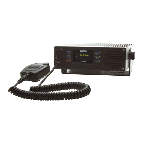
jotron TR-910 User manual

TR-
910
Multipurpose VHF Airband Radio
Operator, Installation and Technical Manual

Safety Instrucons
ELECTROSTATIC SENSITIVE DEVICE:
This equipment contains CMOS integrated circuits. Observe handling
precauons to avoid stac discharges which may damage these devices.
HEARING IMPAIRMENT HAZARD:
Avoid listening at high volume levels for long periods.
ELECTRICAL SHOCK HAZARD:
Do not open the equipment.
Only qualified personnel should work inside the equipment.
Disclaimers
The informaon in this paper has been carefully checked and is believed to be accurate. However, Jotron AS
assumes no responsibility for inaccuracies.
Jotron AS reserves the right to make changes without further noce to any products or modules described
herein to improve reliability, funcon or design. Jotron AS does not assume any liability arising out of the
applicaon or use of the described product.
2jotron.com Doc. No.: 103614 TR-910 Operator Rev. AB

FCC Compliance Statement
This device complies with part 15 of the FCC Rules. Operaon is subject to the following two condions: (1)
This device may not cause harmful interference, and (2) this device must accept any interference received,
including interference that may cause undesired operaon.
CAUTION: Changes or modificaons not expressly approved by the party responsible for compliance could
void the user’s authority to operate the equipment.
NOTE: This equipment has been tested and found to comply with the limits for a Class B digital device,
pursuant to part 15 of the FCC Rules. These limits are designed to provide reasonable protecon against
harmful interference in a residenal installaon. This equipment generates, uses and can radiate radio
frequency energy and, if not installed and used in accordance with the instrucons, may cause harmful
interference to radio communicaons. However, there is no guarantee that interference will not occur in a
parcular installaon. If this equipment does cause harmful interference to radio or television recepon,
which can be determined by turning the equipment offand on, the user is encouraged to try to correct the
interference by one or more of the following measures:
— Reorient or relocate the receiving antenna.
— Increase the separaon between the equipment and receiver.
— Connect the equipment into an outlet on a circuit different from that to which the receiver is connected.
— Consult the dealer or an experienced radio/TV technician for help.
Doc. No.: 103614 TR-910 Operator Rev. AB jotron.com 3

ISED Canada Compliance Statement
CAN ICES-3(B) / NMB-3(B)
This radio transmier [TR-910 IC: 2131A-TR910] has been approved by Innovaon, Science and Economic
Development Canada to operate with the antenna types listed below, with the maximum permissible gain
indicated. Antenna types not included in this list that have a gain greater than the maximum gain indicated
for any type listed are strictly prohibited for use with this device.
Le présent émeeur radio [TR-910 IC: 2131A-TR910] a été approuvé par Innovaon, Sciences et
Développement économique Canada pour fonconner avec les types d’antenne énumérés ci-dessous et ayant
un gain admissible maximal. Les types d’antenne non inclus dans cee liste, et dont le gain est supérieur au gain
maximal indiqué pour tout type figurant sur la liste, sont strictement interdits pour l’exploitaon de l’émeeur.
Table 4: Antenna List
List of Antenna types / Liste des types d’antenne
Antenna type Antenna Part Maximum Antenna Gain Impedance
No dBd
Whip 1/4λAntenna (Man Portable kit) 86875 0.0 50
Whip 1/4λAntenna with cable (Vehicle kit) 97976 0.0 50
Whip Generic - 0.0 50
Dipole Generic - 0.0 50
4jotron.com Doc. No.: 103614 TR-910 Operator Rev. AB

Radio Frequency Radiaon Exposure
NOTICE: This radio is intended for use in occupaonal/controlled condions, where users have full knowledge
of their exposure and can exercise control over their exposure to meet FCC/ISED limits. This radio device is
NOT authorized for general populaon, consumer, or any other use.
The device antenna radiates RF energy only during transmit mode, and not during receive or idle mode. Do not
transmit when any person(s) are within the specified separaon distance as specified below from the antenna.
Man Portable (MP) and Vehicle (VE) Version:
This device complies with the FCC/ISED RF exposure limits with up to 50% talk - 50% listen duty factor and the
separaon distance as specified below.
To comply with FCC/ISED RF exposure limits for occupaonal/controlled exposure, the antenna(s) used for
this transmier must be installed to provide a separaon distance of at least 40 cm from any persons and
must not be co-located or operang in conjuncon with any other antenna or transmier.
All Other Versions:
All other device versions comply with the FCC/ISED RF exposure limits with up to 100% talk - 0% listen duty
factor and the separaon distance as specified below.
To comply with FCC/ISED RF exposure limits for occupaonal/controlled exposure, the antenna(s) used for this
transmier must be installed on outdoor permanent structures to provide a separaon distance of at least
140 cm from any persons and must not be co-located or operang in conjuncon with any other antenna or
transmier.
Man Portable (MP) Version Operang Instrucons
To ensure compliance with the RF exposure requirements the device must be placed to allow a minimum
separaon distance of 40 cm between the antenna and all persons during transmit mode operaon as shown
in figure 1.
Vehicle (VE) Version Antenna Installaon
The vehicle antenna used for this transmier must be installed external to a metal body vehicle and provide a
separaon distance of 40 cm from passenger and bystanders.
For opmum performance and compliance with RF exposure limits, mount the antenna in the center area of
the roof as shown in figure 2.
Figure 1: Operaon of Man Portable Figure 2: Installaon of vehicle antenna
Doc. No.: 103614 TR-910 Operator Rev. AB jotron.com 5

Exposion aux fréquences radio
AVIS: Cee radio est desnée à être ulisée dans un environnement professionnel et maitrisé, où les
ulisateurs ont conscience de leur exposion et peuvent y exercer un contrôle pour répondre aux limites
de la FCC/ISED. Ce disposif radio n’est PAS autorisé pour le grand public ou toute autre ulisaon par des
consommateurs parculiers.
L’antenne émet de l’énergie RF seulement en phase de transmission, pas en mode de récepon ou en mode
inacf. Ne pas transmere si quelqu’un se trouve dans les limites de distance indiquées en dessous de
l’antenne.
Version Man Portable (MP) et Version Vehicle (VE):
Cet appareil est conforme aux limites d’exposion RF FCC/ISED avec un taux de service allant jusqu’à 50%
parole - 50% écoute et la distance d’éloignement comme indiquée en dessous.
Pour être conformes aux limites professionnelles d’exposion RF FCC/ISED, les antennes ulisées pour ce
transmeeur doivent être installées avec une distance d’éloignement d’au moins 40 cm pour toute personne
et ne doivent pas être mises en fonconnement assemblées avec d’autres antennes ou transmeeurs.
Autres Versions:
Toute autre version de cet appareil est conforme aux limites d’exposion RF FCC/ISED avec un taux de service
allant jusqu’à 100% parole - 0% écoute et la distance d’éloignement comme indiquée en dessous.
Pour être conformes aux limites professionnelles d’exposion RF FCC/ISED, les antennes ulisées pour ce
transmeeur doivent être installées en extérieur afin de respecter une distance d’éloignement d’au moins 140
cm pour toute personne et ne doivent pas être mises en fonconnement assemblées avec d’autres antennes
ou transmeeurs.
Mode d’Emploi de la Version Man Portable (MP)
Pour être conforme aux condions d’exposion RF, cet appareil doit être placé en respectant une distance
d’éloignement de 40 cm entre l’antenne et toute personne en mode de transmission comme illustré sur la
figure 1.
Installaon de l’Antenne en Version Vehicle (VE)
L’antenne de véhicule ulisée pour ce transmeeur doit être installée de manière externe au corps métal du
véhicule et donner une distance d’éloignement de 40 cm aux passagers. Pour une performance opmale et
une conformité aux limites d’exposion RF, monter l’antenne au milieu du toit comme illustré sur la figure 2.
6jotron.com Doc. No.: 103614 TR-910 Operator Rev. AB

Document Revision Log
AB 17.11.2021 Revised FCC/ISED statements GAJ
AA 15.10.2021 Inial Issue BA / GAJ
Rev. Issue Date
(DD.MM.YY)
Reason for Issue Author
Doc. No.: 103614 TR-910 Operator Rev. AB jotron.com 7

List of abbreviaons and definions
100Base-T 100Mbit/s physical Ethernet adapter to interface to twisted pair (copper wire) LAN.
RJ45 connector is used and range is 100m.
A3E Amplitude Modulaon (double sideband with carrier)
AC Alternang Current
AD Analogue-to-Digital Converter
AF Audio Frequency
AGC Automac Gain Control
AM Amplitude Modulaon
ATC Air Traffic Control
BITE Built-In Test Equipment
C/N Carrier-to-Noise Rao
DA Digital-to-Analogue converter
dB decibel
DSP Digital Signal Processor
EMC Electromagnec Compability
EN European Norm
ETSI European Telecommunicaon Standardizaon Instute
Ethernet Computer network, physical connecon. (IEEE 802.3)
FW Firmware, The control program stored in non-volale memory of the embedded
radio system
GP I/O/IO General Purpose Input/Output/Input-Output
HW Hardware
ICAO Internaonal Civil Aviaon Organizaon
IEC Internaonal Electro-technical Commission.
IMO Internaonal Marime Organizaon
IF Intermediate Frequency
IP Internet Protocol
LAN Local Area Network
LO Local Oscillator
LOS Line of Sight
LRM Lowest Replaceable Module
LRU Lowest Replaceable Unit
MIB Management Informaon Base is a virtual database used for managing the objects
(parameters) in a communicaons network. Most oen associated with the Simple
Network Management Protocol (SNMP). The MIB database is hierarchical (tree-
structured). The soware that performs the navigaon in the MIB database is a
MIB browser. The MIB database is Jotron proprietary and contains descripons and
definions for all parameters in the radio. The MIB database is updated each me a
new radio parameter is added or changed.
MHz Mega Hertz
MTBF Mean Time Between Failure
MTTR Mean Time to Repair
PA Power Amplifier
PCB Printed Circuit Board
8jotron.com Doc. No.: 103614 TR-910 Operator Rev. AB

ppm Parts Per Million
PTT Push-to-Talk
RCMS Remote Control and Management System, usually an IP-based network to monitor
and control radios and accessories (=RACS).
RF Radio Frequency
RSSI Received Signal Strength Indicator is a measurement of the power present or level
of a received radio signal.
Rx Receiver, Recepon
RTP Real-me Transport Protocol. Used for Voice Over IP (VoIP).
SDR Soware-Defined Radio is a system where components that tradionally have been
implemented in hardware (e.g. mixers, filters, amplifiers, modulators/demodulators,
detectors, etc.) now are implemented by means of soware on an embedded
compung devices, i.e. a Digital Signal Processor (DSP).
SIP Session Iniaon Protocol is an IETF-defined signaling protocol, widely used for
controlling mulmedia communicaon sessions such as voice and video calls over
the Internet Protocol (IP). The protocol can be used for creang, modifying and
terminang two-party (unicast) or mulparty (mulcast) communicaon sessions
consisng of one or several media streams.
S/N Signal-to-Noise Rao
SNMP Simple Network Management Protocol is a UDP-based network protocol. It is used
mostly in network management systems to monitor and control network connected
devices like the Jotron radios. SNMP is a component of the Internet Protocol
Suite as defined by the Internet Engineering Task Force (IETF). It consists of a set
of standards for network management, including an applicaon layer protocol, a
database schema, and a set of data objects.
SQ Squelch
SW Soware
TCP Transmission Control Protocol
TCXO Temperature Compensated Crystal Oscillator.
TRx Transceiver
Tx Transmier, transmission
UDP User Datagram Protocol
VCO Voltage-controlled Oscillator
VHF Very High Frequency (VHF is defined by the band 30-300 MHz). In the content of this
book, it refers to the internaonal communicaon band for air traffic control (118-
137 MHz)
VOGAD Voice Operated Gain-Adjusng Device is a type of automac gain control for
microphone/TX line amplificaon. It is used in radio transmiers to ensure correct
modulaon and to prevent clipping caused by overmodulaon.
VoIP Voice over IP (VoIP) is a general term for a family of transmission technologies for
delivery of voice communicaons over IP networks such as the intranet/Internet or
other packet-switched networks.
VSWR Voltage Standing Wave Rao
Doc. No.: 103614 TR-910 Operator Rev. AB jotron.com 9

CONTENTS
Contents
1 Introducon 11
1.1 Design ............................................... 11
1.2 Applicaons............................................ 11
1.3 Models covered by this manual .................................. 11
1.4 Opons .............................................. 13
2 Technical Specificaons 14
2.1 General specificaons....................................... 14
2.2 Transmier specificaons..................................... 15
2.3 Receiver specificaons ...................................... 16
2.4 Applicable standards ....................................... 17
3 Funconal Descripon 18
3.1 Front panel controls and connector ................................ 18
3.1.1 Display .......................................... 18
3.1.2 Scroll/Select knob ..................................... 19
3.1.3 Shortcut keys ....................................... 20
3.1.4 Mic/Headset connector (RJ45) .............................. 20
3.2 Rear connecons ......................................... 21
3.2.1 Antenna connector (50 ΩBNC) .............................. 21
3.2.2 DC input connector .................................... 21
3.2.3 LAN connector (RJ45) ................................... 22
3.2.4 I/O connector (RJ45) ................................... 22
4 Installaon 24
4.1 Introducon............................................ 24
4.2 Inial inspecon.......................................... 24
4.3 Compass safe distance ...................................... 24
4.4 Installaon of TR-910 ....................................... 25
4.4.1 TR-910 Desktop Radio (DE) ................................ 25
4.4.2 TR-910 Man Portable Radio (MP) ............................ 26
4.4.3 TR-910 Vehicle Radio (VE) ................................ 30
4.4.4 TR-910 Last Resort Radio (LR) .............................. 31
4.4.5 TR-910 Subrack Radio (SR) ................................ 32
4.4.6 TR-910 Last Resort Subrack Radio (LR-SR) ........................ 33
4.4.7 TR-910 Offshore Radio (OF) . . ............................. 34
4.4.8 Antenna connecon ................................... 35
4.4.9 DC supply connecon................................... 35
4.4.10 LAN connecon...................................... 35
4.4.11 I/O connecon ...................................... 35
5 Operang Instrucons 37
5.1 Introducon............................................ 37
5.2 Note on frequency seng .................................... 37
5.3 Basic Operaon.......................................... 39
5.3.1 Turning the unit ON/OFF ................................. 39
10 jotron.com Doc. No.: 103614 TR-910 Operator Rev. AB
CONTENTS
5.3.2 Home screen - Channel shortcuts ............................ 39
5.3.3 Volume screen - Seng audio volume level ....................... 39
5.3.4 Volume screen - Seng display brightness and contrast ................ 40
5.3.5 Funcon screen - Recall channel ............................. 40
5.3.6 Funcon screen - Seng squelch level .......................... 41
5.3.7 Funcon screen - Seng frequency and channel store ................. 41
5.3.8 Funcon screen - Show radio informaon........................ 42
5.3.9 Funcon screen - Advanced sengsmenu ....................... 42
6 Advanced sengs 43
6.1 Configuraongroup........................................ 44
6.1.1 AM ............................................ 44
6.1.2 Audio ........................................... 44
6.1.3 Single channel mode ................................... 46
6.2 Service menu group ........................................ 47
6.2.1 Language ......................................... 48
6.2.2 Access menu ....................................... 48
6.2.3 Squelch .......................................... 48
6.2.4 Keying ........................................... 49
6.2.5 IO config ......................................... 50
6.2.6 LAN ............................................ 51
6.2.7 IPv6 . . .......................................... 53
6.2.8 Locaon.......................................... 54
6.2.9 Secure Mode ....................................... 54
6.2.10 Calibrate ......................................... 55
6.2.11 Service Mode ....................................... 55
6.2.12 Preset ........................................... 55
6.3 Bitesystemgroup......................................... 56
6.3.1 Alarm . .......................................... 56
6.3.2 Measurements ...................................... 56
6.4 SystemInfogroup......................................... 61
6.4.1 System info ........................................ 61
7 Failures and Correcve Acons 63
7.1 Alarms ............................................... 63
7.2 Alerts ............................................... 63
7.3 System components ........................................ 63
7.4 Transceiver error condions ................................... 63
8Baery Unit 67
8.1 Technical specificaons...................................... 67
8.2 Front panel ............................................ 68
8.2.1 LED Indicators ....................................... 68
8.2.2 Test key .......................................... 68
8.3 Rear connecon.......................................... 69
8.3.1 DC input .......................................... 69
8.3.2 Radio connector ..................................... 69
8.3.3 Ext connector ....................................... 69
Doc. No.: 103614 TR-910 Operator Rev. AB jotron.com 11

CONTENTS
8.3.4 DC output ......................................... 70
8.4 TR-910 Baery indicator ..................................... 70
8.5 Baery maintenance ....................................... 70
8.5.1 Maintenance charge . . ................................. 70
8.5.2 Balancing procedure ................................... 71
8.6 Balancing procedure instrucons................................. 71
8.7 Storage of BU-872 ......................................... 73
9 Using the radio with the VoIP interface 75
9.1 Introducon............................................ 75
9.2 ED-136 compliance ........................................ 76
9.3 ED-137 compliance ........................................ 76
9.4 Configuraon when using ED-137 VoIP towards a voice control system ............. 78
9.4.1 SIP iniaon ....................................... 78
9.4.2 Configurable parameters used by ED-137 connecons ................. 79
9.5 Configuraon when using stac VoIP towards a voice control system .............. 81
9.5.1 Bandwidth consideraons when using VoIP ....................... 81
9.5.2 Delay consideraons ................................... 83
9.5.3 Vendor specificfields ................................... 85
9.5.4 Delay compensaon when using receivers in a best signal select system ........ 88
9.6 Configuraon to use the radio against an ED-137 VoIP recorder ................. 88
9.6.1 Configuraon....................................... 89
10 List of Tables and Figures 90
12 jotron.com Doc. No.: 103614 TR-910 Operator Rev. AB
1 Introducon
1.1 Design
The TR-910 is a compact, high-quality radio available in a variety of configuraons to meet the high demands
of the ATC and Oil and Gas industries where a small, rugged and durable radio unit is needed. The radio
has an all metal housing, making it very robust but sll light enough to be carried as a manpack. It is a fully
solid-state design based on a Soware-Defined Radio (SDR) concept, making it very versale, future proof and
firmware upgradeable. It also includes a LAN interface for remote configuraon and digital recording and is
fully compliant to ED-137 with the VoIP opon enabled.
TR-910 meets or outperforms all radio requirements specified in ETSI EN300676 and EN301489 (EMC). It
supports both 25kHz and 8.33kHz channels in accordance with ICAO recommendaons.
1.2 Applicaons
Listed below are some of the possible applicaons of the TR-910 radio:
• Installed as a desktop unit, with microphone and/or headphone connected to the front connector. An
external loudspeaker can be connected to the transceiver unit if required.
• Man Portable version, enclosed in a shoulder/carrying bag, with baery pack, antenna and microphone
(or headset) connected. An external baery charger can be connected for charging the baery pack as
and when required.
• Internally mounted in a vehicle, with microphone connected to the front module connector. An external
loudspeaker can be connected to the transceiver unit if required.
• Flush mounted on a horizontal or vercal plate, with microphone and/or headphone connected to the
front connector. An external loudspeaker can be connected to the transceiver unit if required.
• Remote configuraon and monitoring through the LAN interface via the Jotron Remote Control and
Monitoring System (RCMS).
• With VoIP opon is enabled, the TR-910 also fully supports ED-137 and facilitates up to two remote
sessions and two recording streams. It is possible to expand this funcon by the inclusion of ”Enhanced
VoIP”. This will increase the number of sessions to 4 and recording streams to 3.
1.3 Models covered by this manual
Table 7: Radio models covered by this manual
The following models /versions are covered by this manual
Model P/N Output Frequency Mode
TR-910 Desktop Radio (DE) 103400DE 10 Wa118-137 MHz AM
TR-910 Man Portable Radio (MP) 103400MP 5Wa118-137 MHz AM
TR-910 Vehicle Radio (VE) 103400VE 10 Wa118-137 MHz AM
TR-910 Last Resort Radio (LR) 103400LR 10 Wa118-137 MHz AM
TR-910 Subrack Radio (SR) 103400SR 10 Wa118-137 MHz AM
TR-910 Last Resort Subrack Radio (LR-SR) 103400LR-SR 10 Wa118-137 MHz AM
Doc. No.: 103614 TR-910 Operator Rev. AB jotron.com 13

1.3 Models covered by this manual
TR-910 Offshore Radio (OF) 103400OF 10 Wa118-137 MHz AM
TR-910 Mulpurpose VHF Airband Radio (no accessories) 103400 10 Wa118-137 MHz AM
Table 8: Accessory list
Accessory list
Supplied accessory Part TR-910 TR-910 TR-910 TR-910 TR-910 TR-910 TR-910
X = Standard, O = Oponal No DE MP VE LR SR LR-SR OF
Hand Speaker Mic 103116 X X X X X X X
Console bracket 84084 X X X X
Lock screws 84086 X (4x) X (8x) X (4x) X (4x)
Mains cable w/plugs 92375 X X X X X X
Power supply
w/connector
84330 X X X
Antenna adapter BNC-N 80577 X X X
BU-872 Baery Unit 87130 X X X
Fasten bracket 85779 X X (2x)
Patch Cable CAT6 S/FTP
0,15m Blue
101669 X X
Screw M4x8 T20 102281 X (8x) X X
Serrated Lock Washer 102341 X (8x) X (8x) X X X (4x)
Antenna 86875 X
Antenna bracket 85778 X
Antenna cable
w/connector
85781 X
DC power cable 86026 X
Power AC/DC with car
lighter plug
86918 X
Insert Carrying Bag 103617 X
Shoulder/Carrying Bag 85636 X
Cable Tie 92161 X (4x)
Antenna with cable
(Vehicle kit)
97976 X
Antenna adapter FME -
BNC
84605 X
DC cable 84329 X
External Speaker 85558 X
Fuse Kit 103079 X
Cable RG174 with BNC-
male and N-female
83233 X
Spacer M4x2mm 86652 X
Support knob 97975 X
RG-214 N-male
Connector
86273 X X
14 jotron.com Doc. No.: 103614 TR-910 Operator Rev. AB
1.4 OpƟons
Table 8: Accessory list
Accessory list
Supplied accessory Part TR-910 TR-910 TR-910 TR-910 TR-910 TR-910 TR-910
X = Standard, O = Oponal No DE MP VE LR SR LR-SR OF
XLR Connector, Female 3-
pol
87315 X X
TR-910 2U/19” Subrack
for SR
X
TR-910 2U/19” Subrack
for LR-SR
X
Panel Mounng Plate 103477 X
Panel Mounng Bracket 103478 X (2x)
Screw M4x10 T20 102282 X (4x)
Screw M4x12 T20 88366 X (4x)
Antenna lightning
protector
80322 O O O
Base antenna 91794 O
Coax cable RG-213 - 30m 97898 O
Discharge unit 86991 O O O
N-connector for RG-213 98244 O
1.4 Opons
The transceiver may have the following addional funcons if required. These opons must be specified
separately when ordering.
Table 9: Available radio opons
Oponal funcons Descripon Part number
VoIP Enables VoIP with 2 sessions and 4 recording
streams
102253
Enhanced VoIP Increase number of sessions to 4. Allows the use
of 5ms packets for VoIP to reduce delay in a VoIP
system. Requires VoIP opon
102777
Extended frequency range Extended operang frequency to 144.000 MHz 84360
G.729 Adds the possibility to use G.729 codecs for the
audio streams in addion to G.711 to reduce
bandwidth. Requires VoIP opon
81432
Doc. No.: 103614 TR-910 Operator Rev. AB jotron.com 15

2.1 General specificaƟons
2 Technical Specificaons
2.1 General specificaons
Table 10: General specificaons
Parameter Specificaons
AM 25 kHz AM 8.33 kHz
Frequency range 118.000 to 137.000 MHz (up to 144.000 MHz is oponal)
Frequency stability < ±1.0 ppm @ -20 °C to +55 °C,
<±0.3ppm@0°Cto+40°C(ambient temperature)
RF Modes 6K80A3EJN 5K00A3EJN
Audio Frequency Response 300 - 3400 Hz 300 - 2500 Hz
Data ports 100Base-TX (Ethernet/LAN), USB 2.0 (for service / setup only)
Ethernet ports 1 x 100 Mbit network
Protocols UDP/IP: SNMP (v.1, 2 and 3), RTP, SIP, NTP, TFTP, DHCP, RTSP
TCP/IP: Remote control (Jotron), RTP, SIP, HTTP, RTSP
Serial: USB 2.0
BITE monitoring All relevant parameters for transceiver. Ref. BITE below.
Pre-set channels 100
RF impedance 50 Ω, BNC-connector
Temperature range -20 °C to +55 °C (operang), -40 °C to +70 °C (storage)
Humidity 95 % @ +40 °C (non-condensing)
Operang voltage 12 - 24 VDC, negave ground +30/-10 %
Power consumpon At 10 W, 80 % modulaon: < 60 W
At idle: < 5.0W@12V,<5.6W@28V
At standby: < 1.3 mW @ 12 V, < 7.2 mW @ 28 V
Heat dissipaon <5W@Idle, < 50W@10Woutput power
MTBF (MIL-HDBK-217F) Ground Benign (GB): > 20 years / unit
Ground Mobile (GM): > 10 years / unit
MTTR < 30 minutes at lowest replaceable unit
Dimension 169 mm (W) * 244 mm (D) * 55 mm (H)
Weight 1.95 kg
Start-up me <10sfrompoweronunl transceiver is available for use on all
audio and control interfaces, including the IP interface.
16 jotron.com Doc. No.: 103614 TR-910 Operator Rev. AB
2.2 TransmiƩer specificaƟons
2.2 Transmier specificaons
Table 11: Transmier specificaons
Parameter Specificaons
AM 25 kHz AM 8.33 kHz
Power output 10 W, Adjustable in 0.1 dB step down to 1 W (30.0 up to 40.0
dBm).
Automacally reduced if high VSWR is detected.
VSWR 1:Infinity. Protected against shorted and open circuit
Adjacent channel power >70dBc
Modulaon depth up to 95 %
Distoron <2%@85%modulaon
In-band spurious emissions ≤-100 dBc (-60 dBm @ 10 W output)
Harmonic emission ≤-80 dBc (-40 dBm @ 10 W output)
Intermodulaon aenuaon Typically ≤-50 dBc, 3. Order intermodulaon (EN300676,7.8)
Power aack and release me <3msaack, < 2 ms release me
Keying Time <10ms
Mic input Support dynamic and electret types with adjustable sensivity.
Mic Bias is selectable
Line input 600 Ω, -40 to +10 dBm, adjustable sensivity, single ended
AGC (VOGAD) range >30dB
Keying opons Mic/Headset connector, I/O connector (configurable input),
SNMP, TCP/IP, RTP header
Signal/Noise (Hum and noise) >40dB
Timeout 5 s to 5 min (300 s) in 5 s. steps (1 s from SNMP)
Duty cycle 30 % Tx/Rx operaon @ ambient below 40 °C
Doc. No.: 103614 TR-910 Operator Rev. AB jotron.com 17
2.3 Receiver specificaƟons
2.3 Receiver specificaons
Table 12: Receiver specificaons
Parameter Specificaons
AM 25 kHz AM 8.33 kHz
Sensivity, AM@1μV/30% pd > 12 dB SINAD (CCITT)
Harmonic distoron <2%@90%AM(line output), Typically < 1 %
Signal/Noise > 55 dB @ +10 dBm input, 90 % modulaon
Effecve bandwidth ±10 kHz ±3.5 kHz
Adjacent channel rejecon
(Adjacent channel selecvity)
Typical figures
>80dB >70dB
In-band spurious rejecon >90dB
Intermodulaon aenuaon ≥85 dB
Image frequency rejecon > 110 dB
IF frequency rejecon > 110 dB
Blocking/desensizaon ≥100 dB @ 1 MHz offset, > 110 dB out-of-band signals
Squelch system Combinaon of RF level and Carrier/Noise (digital coherent
squelch)
Squelch RF level -5 to +42 dBμV (-112 to -65 dBm)
Squelch Signal/Noise 5 to 20 dB S/N @ 30 % modulaon
Squelch hysteresis Typical 2-4dB
Squelch mute level ≥70 dB
Cross modulaon rejecon > 100 dB @ 1 MHz frequency offset
Dynamic range > 125 dB (-110 to +15 dBm input signal)
Audio AGC (AAGC) 30 % to 90 %, < 0.1 dB variaon in output audio signal
AGC range -107 to +15 dBm
AGC aack me <40ms
AGC decay me <50ms
Internal speaker amplifier 5W@8Ω
Headset 8to32Ω, > 100 mW
External speaker amplifier 5W@8Ω
Monitor output 600 Ω, -46 to 0 dBm @ 90 % modulaon, single ended
Permissible RF input level 5 V EMF
18 jotron.com Doc. No.: 103614 TR-910 Operator Rev. AB

2.4 Applicable standards
Table 13: Applicable standards
Applicable standards
Radio performance ETSI EN 300 676-1 V1.5.2
ICAO annex 10
Voice over IP EUROCAE ED-137 (B, C) part 1,4 and 5
EMC ETSI EN 301 489-1 V2.2.3
ETSI EN 301 489-22 V2.1.1
IEC/EN 60945 Ed.4 + Cor1:2008 (Protected)
FCC/ISED FCC rule 15B and 87, ICES-003 and RSS-141
Shock & Vibraon ETSI EN 300 019-2-2 V2.4.1: Transportaon
ETSI EN 300 019-2-5 V3.1.1: Ground Vehicle Installaons
ETSI EN 300 019-2-7 V3.0.1: Portable and non-staonary use
Safety IEC 62368-1:2014 + A11:2017
RoHS EN 50581
Doc. No.: 103614 TR-910 Operator Rev. AB jotron.com 19

3 Funconal Descripon
3.1 Front panel controls and connector
Mic/Headset
connector
Mic/Headset
connector
Scroll / Select
knob
Scroll / Select
knob DisplayDisplay
Shortcut keysShortcut keys LoudspeakerLoudspeaker
Figure 3: Front view of TR-910
3.1.1 Display
The display shows the most important operaonal parameters such as selected channel/frequency, modulaon
and indicator icons. In addion, the display will show various menus and submenus which can be navigated
using the scroll/select knob and shortcut keys on the front panel.
The indicator icons appear at the leand right side of the display during operaon. Some icons share posion
in the display and are with descending priority listed in the table below.
Table 14: Indicator icons
Icon Descripon
Leside area:
Indicates that the transceiver is keyed, and the radio is transming.
Indicates that the SWR on the antenna is above the threshold value (app. 3:1).
The transmier will reduce the output power to the predefined low power
level in order to protect the output stage.
20 jotron.com Doc. No.: 103614 TR-910 Operator Rev. AB
Table of contents
Other jotron Radio manuals

jotron
jotron TR-7750C User manual

jotron
jotron Tron TR30 AIR User manual

jotron
jotron Tron TR30 User manual

jotron
jotron Tron TR30 AIR User manual

jotron
jotron Tron TR30 User manual

jotron
jotron TR-810 User manual

jotron
jotron Tron TR20 GMDSS User manual

jotron
jotron Tron TR30 User manual

jotron
jotron Tron TR20 PLUS User manual