Westward 23V746 Service manual

Read through this owner’s manual carefully. Failure to comply with instructions could result in
injury and/or product or property damage. Please retain instructions for future reference.
Operating Instructions and Parts Manual 23V746
Circuit Breaker Finder
Manufactured for Grainger International, Inc.
Printed in China
09/12
Form # TI-1168
Circuit Breaker Finder
The Circuit Breaker Finder helps you locate AC circuits quickly and
easily. You no longer have to guess where the correct circuit breaker
supplies power to an AC outlet or lighting fixture.
Unpacking
The unit comes with a transmitter, a receiver, and a manual.
Receiver and Transmitter Description
Receiver
1. Scanning Head
2. LED Indicator (red during auto-scanning)
3. Signal LED Indicator
4. On/Off/Reset button*
5. Battery Compartment
Transmitter
6. LED indicator
Note:
No switch on the transmitter, it will
automatically operate once connected to
the socket.
Picture 2
Specifications
Operating Voltage 110 /240VAC
Operating Frequency 50 to 60 Hz
Current Consumption <20 mA
Power Supply 9VDC battery (Receiver)
Operating Temperature 14ºF to 122ºF (-10ºC to 50ºC)
Operating Humidity 10% to 80%
Storage Temperature 68ºF to 104ºF (20ºC to 40ºC)
Storage Humidity 30% to 70%
Altitude 7,000 ft (2, 000 meters) Max.
Picture 1

2
Westward Operating Instructions and Parts Manual 23V746
Circuit Breaker Finder
Dimensions
Overall Dimension: (In±10%)
Receiver: 2-7/32x1-13/32x7-11/16;
Transmitter: 1-13/32x2-13/32x4-11/16
Be extremely careful when working around AC circuits, shock hazards may exist.
Do not use in cardiac care areas.
If used on a circuit controlled by a dimmer, turn the dimmer to the highest position.
Refer all indicated problems to a qualified electrician.
Operation Instructions
Self- Function Check before testing
1. Turn on the receiver, you will hear a beeping and see a red LED light.
2. Connect the transmitter to the receptacle. Move the receiver’s scanning head over the
face of the transmitter as shown in picture 3, it will beep at higher frequency or even
change to a continuous sound if closer to transmitter. The signal LED should turn green
when the scanning head detects a signal.
Picture 3
Note on ON/OFF/RESET button:
a. To turn on the receiver, press and release the button immediately. You will hear a
steady beeping and see a red LED, which indicates the scanning begins.
b. To turn off the receiver, press and hold the button for at least one second.
c. To reset all scanning function memory to zero, press and release the button
immediately when the receiver is on. You will hear a steady beeping, and see a red
LED.

3
Westward Operating Instructions and Parts Manual 23V746
Circuit Breaker Finder
Locating a Circuit Breaker or Fuse
1. Plug the transmitter into the receptacle, the red LED will be illuminated.
2. Go to the circuit breaker panel box.
3. Turn on the receiver, you will hear a beeping and see a red LED light.
4. Place the scanning head onto the surface of the circuit breaker or fuses as picture 4
shown.
5. Slide the scanning head steadily along the row of circuit breakers. The receiver will
beep frequently or even switch to continuous sound and the signal LED will turn green
when it detects the relative stronger signal. The signal comes out only once the
scanning head meets a breaker powering the transmitter.
Picture 4
6. Turn off the breaker, the receiver will revert to a red LED display and a steady beeping,
the red LED on the transmitter is not lit, you can confirm that the correct breaker or
fuse has been found.
Note:
9If the receiver is getting closer to correct circuit breaker, the red LED starts flashing
and then no indication after a while, it’s normal, as the receiver finds a weak signal.
You can reset it to look for new signals.
9If the signal is coming from two adjacent circuit breakers and it is difficult to
distinguish which one, please complete the:
a. Scan the breaker on the opposite side of the switch (after resetting the receiver),
the strongest signal may be found at the top of the breaker. (Picture 5)
b. Rotate the receiver 90° (after reset) so the scanning head comes in line with the
breaker, the strongest signal can be found at the new angle. (Picture 6)

4
Westward Operating Instructions and Parts Manual 23V746
Circuit Breaker Finder
Picture 5 Picture 6
Locating an Incandescent Light Fixture
1. If the incandescent light fixture is controlled by a wall switch, make sure the wall
switch is OFF.
2. Remove light bulb.
3. Install a screw-in socket adapter (not included).
4. Plug the transmitter into the adapter.
5. Turn on the wall switch and follow the procedure described in Locating a Circuit
Breaker or Fuse, steps 3 through 6.
Maintenance
Replacing the Battery
1. When the battery power reaches 20%, you will see a flashing green LED light and
hear beeping, indicating the battery is low and needs to be replaced. The receiver may
shut down shortly after the beeping.
2. Remove battery compartment cover.
3. Install 9-Volt battery.
4. Reinstall battery cover.
5. Dispose of old battery properly.
Note:
To maximize battery life, the receiver has an Auto Power Off function after three minutes
of inactivity.
Cleaning
Wipe the exterior surface of the transmitter and receiver with a damp cloth or cleansing
wipe. Do not use solvents. Dry thoroughly before use.

5
Westward Operating Instructions and Parts Manual 23V746
Circuit Breaker Finder
Troubleshooting Chart
SymSymptoms PossibPossible Cause(s) CorrectivCorrective Action(s)
LED will not operate
1. Loose bulb
2. ON/OFF switch in OFF
position
3. Low battery
1. Check bulb installation
2. Put ON/OFF switch in
ON position
3. Replace battery
Receiver can’t search
signal
1. Transmitter not working
2. Scanning head loose
3. Signal very weak
1. Connect transmitter to socket
2. Check scanning head
3. Press reset switch once
LIMITED ONE-YEAR WARRANTY
Should this product fail to perform satisfactorily due to a defect or poor workmanship within ONE
YEAR from the date of purchase, return it to the place of purchase and it will be replaced, free of
charge. Incidental or consequential damages are excluded from this warranty.
Manufactured for Grainger International, Inc.
100 Grainger Pkwy., Lake Forest IL 60045
U.S.A.

Lea atentamente este manual. Si no cumple con las instrucciones, puede resultar en lesions y/o
daños al producto o al propietario. Por favor, conserve las instrucciones para futuras consultas.
Insturcción y manual de Operación 23V746
Buscador de Interruptor
de Circuito
Fabricado para Grainger International, Inc.
Imprimido en China
09/12
Form # TI-1168
Buscador de Interruptor de Circuito
El buscador de interruptor de Circuito le ayuda rápidamente y
fácilmente localizar circuitos de corriente alterna. Ya no tiene que
adivinar dónde está el interruptor correcto de circuito suministrando la
potencia a una toma de corriente alterna o un accesorio de iluminación.
Desembalaje
La unidad viene con un transmisor, receptor y este manual.
Descripción de receptor y transmisor
Receptor
1. Cabeza de escáner
2. Indicador LED (rojo durante auto-escáner)
3. Indicador de señal LED
4. On/Off/botón de restablecimiento
5. Compartimiento de batería
Transmisor
6. Indicador LED
Nota:
No encienda el transmisor, que va a
operar automáticamente una vez
conectado al enchufe.
Picture 2
Especificaciones
Voltaje de Operación 110 /240VAC
Frecuencia de Operación 50 a 60 Hz
Consumo de Corriente <20 mA
Frecuencia de Operación 9VDC batería (Receptor)
Temperatura de Operación 14ºF a 122ºF (-10ºC a 50ºC)
Humedad de Operación 10% a 80%
Temperatura de Almacenamiento 68ºF a 104ºF (20ºC a 40ºC)

2
Instrucciones y Manual de Operación de Westward 23V746
Buscador de Interruptor
de Circuito
Humedad de Almacenamiento 30% a 70%
Altitud 7.000 ft (2.000 metros) Max.
Dimensiones
Dimensión general: (In±10%)
Receptor: 2-7/32x1-13/32x7-11/16;
Transmisor: 1-13/32x2-13/32x4-11/16
ADVERTENCIA
Tenga mucho ciudado al trabajar cerca de circuitos de corriente alterna. Puede existir
peligros de choque.
No lo use en areas de cuidado cardíaco.
Si se utilize en un circuito controlado por un regulador, gire el regulador a la posición
más alta.
Consulte todos los problemas indicados a un electricista calificado.
Instrucciones de Operación
Comprobación antes de prueba de auto-función
1. Encienda el receptor. Se oirá un pitido y verá una luz roja LED.
2. Conecte el transmisor al receptáculo. Mueva la cabeza de escáner del receptor sobre la
cara del trasmisor, como se muestra en la imagen 2. Sonará en una frecuencia muy alta,
incluso va a cambiar el sonido continuo si se acerca al transmisor. La señal LED debe
cambiar en verde cuando la cabeza de escáner detecta una señal.
Imagen 3

3
Instrucciones y Manual de Operación de Westward 23V746
Buscador de Interruptor
de Circuito
Nota en el botón ON/OFF/RESTABLECIMIENTO:
a. Para encender el receptor, pulse y libere el botón inmediatamente. Se escuchará un
pitido continuo y verás una luz roja, que indica que el escáner ya ha comenzado.
b. Para apagar el receptor, pulse y mantenga pulsado el botón al menos de un segundo.
c. Para reajustar toda la memoria de function a cero, pulse y libere el botón
inmediatamente cuando el receptor está encendido. Se escuchará un pitido constante
y verá una luz LED roja.
Localización de Interruptor de Circuito o Fusible
1. Enchufe el transmisor en el receptáculo. El LED rojo se iluminará.
2. Vaya a la caja de circuito del panel del interruptor.
3. Encienda el receptor. Se oirá un pitido y cerá una luz roja LED.
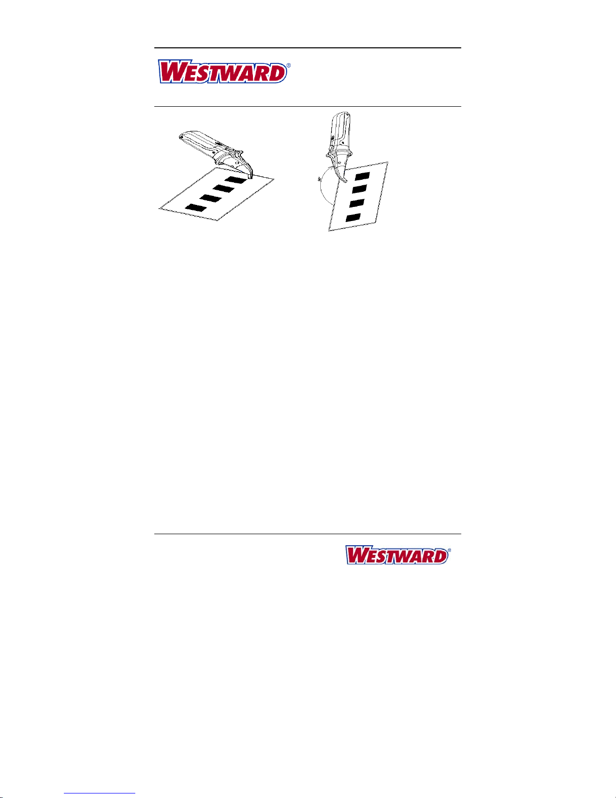
4. Coloque la cabeza de escáner sobre la superficie del interruptor de circuito o los
fusibles, como se muestra en imagen 4.
5. Deslice la cabeza de escáner constantemente a lo largo de la línea de interruptores de
circuito. El receptor emitirá un pitido con frecuencia o incluso va a cambiar en sonido
continuo cuando se detecta la señal relativa más fuerte. La señal sale sola una vez
que la cabeza de escáner se encuentre con un interruptor encendiendo el transmisor.
Imagen 4
6. Apague el interruptor. El receptor volverá a una pantalla LED rojo y un pitido constante.
Si el LED rojo del transmisor no está encendido, se puede confirmar que el interruptor
correcto o el fusible se han encontrado.
Nota:
9Si el receptor se acerca al interruptor de circuito correcto, el LED rojo comenzará a
parpadear y luego, no hay indicación después de un tiempo. Es normal, ya que el
receptor encuentra una señal débil. Usted puede restablecerlo para buscar señales
nuevas.
9Si la señal viene de dos interruptores de circuito adyacentes y es difícil distinguir cuál
es, por favor, complete procesos siguientes:
a. Escanee el interruptor en el lado opuesto del interruptor (después de restablecer
el receptor). La señal más fuerte se puede encontrar en la parte superior del
interruptor. (imagen 5)
b. Gire el receptor 90° (después de restablecerlo) para que la cabeza de escáner
venga en línea con el interruptor. La señal más fuerte se encontrará en un ángulo
nuevo. (imagen 6)

4
Instrucciones y Manual de Operación de Westward 23V746
Buscador de Interruptor
de Circuito
Imagen5 Imagen6
Localización de un accesorio de iluminación incandescente
1. Si el accesorio de la lámpara incandescente se controla por un interruptor de pared,
asegúrese de que el interruptor de pared está apagado.
2. Quite la bombilla.
3. Instale un adaptador de enchufe con tubuladura macho (no está incluído).
4. Enchufe el transmisor en el adaptador.
5. Encienda el interruptor de pared y siga el procedimiento descrito de pasos 3 a 6 en la
localización de un disyuntor o fusible.
Mantenimiento
Sustitución de batería
1. Cuando la batería alcanza a 20%, usted verá una luz intermitente LED verde y ortá
pitidos, lo que indica que la batería está baja y necesita reemplazarse. EL receptor
puede apagarse poco después del pitido.
2. Retire la cubierta del compartimiento de la batería.
3. Instale la batería de 9 voltios, observando la polaridad correcta.
4. Vuelva a instalar la cubierta de la batería.
5. Deshágase de las baterías usadas apropiadamente.
Nota:
Para maximizar la duración de batería, el receptor tiene una función de apagado automático
después de tres minutos de inactividad.
Limpieza
Limpie la superficie exterior del transmisor y el receptor con un paño húmero o toalla de
limpieza. No utilice disolventes. Seque completamente antes de usarlo.

5
Instrucciones y Manual de Operación de Westward 23V746
Buscador de Interruptor
de Circuito
Tabla de Solución de Problemas
Síntoma(s) Posible Causa(s) Acción Correcta(s)
LED no va a
funcionar
1. Bombilla floja
2. ON/OFF en la posición
de OFF
3. Batería baja
1. Compruebe la instalación de
bombilla.
2. Ponga ON/OFF en la posición ON.
3. Reemplace la batería.
El receptor no puede
encontrar señal,
1. El transmisor no
funciona.
2. La cabeza de escáner
está floja.
3. señal muy débil.
1. Conecte el transmisor a la cabeza.
2. Compruebe la cabeza de escáner.
3. Pulse una vez el interruptor de
Restablecimiento.
GARANTÍA LIMITADA DE DOS AÑOS
Si este producto no funcione satisfactoriamente debido a un defecto o una fabricación pobre
dentro de DOS AÑOS desde la fecha de compra, devuélvalo al lugar donde lo compró y se
reemplazará libre de carga. Los daños incidentales o consecuentes quedan excluídos de
esta garantía.
Fabricado para Grainger International, Inc.
100 Grainger Pkwy., Lake Forest IL 60045
U.S.A.

Lisez attentivement ce mode d'emploi. Le non-respect des instructions peut entraîner des
blessures et/ou des dommages au produit ou de la propriété. Veuillez conserver les instructions
pour toute consultation ultérieure.
Notice d'utilisation et Manuel de pièces de Westward 23V746
Disjoncteur Finder
Fabriqué pour Grainger International, Inc.
Imprimé en Chine
09/12
Form # TI-1168
Disjoncteur Finder
Le disjoncteur Finder vous aide à localiser les circuits AC rapidement
et facilement. Vous n'avez plus besoin de deviner où le bon
disjoncteur alimente une prise secteur ou un appareil d'éclairage.
Déballage
L'appareil est livré avec un émetteur, un récepteur et un manuel.
Description du Récepteur et Transmetteur
Récepteur
1. Numérisation chef
2. Indicateur LED (rouge pendant l'auto-
balayage)
3. Signal LED Indicateur
4. Marche / Arrêt / * Réinitialisation
5. Compartiment des piles
Emetteur
6. indicateur LED
Remarquer :
Aucun interrupteur de l'émetteur, il sera
actionné automatiquement une fois
reliée à la douille.
Image 2
Spécifications
Tension de fonctionnement 110/240 V ca
Fréquence de fonctionnement 50 à 60 Hz
Consommation de courant <20 mA
Alimentation d’électricité 9VDC batterie (récepteur)
Température de fonctionnement 14 ºF à 122 ºF (-10 ºC à 50 ºC)
Humidité de fonctionnement 10% à 80%
Température de stockage 68 ºF à 104 ºF (20 ºC à 40 ºC)
Humidité de stockage 30% à 70%
Altitude 7 000 pieds (2 000 mètres) Max.
Ima
g
e1

2
Notice d'utilisation et Manuel de pièces de Westward 23V746
Disjoncteur Finder
Dimensions
Dimension globale : (In ± 10%)
Récepteur : 2-7/32 x 1-13/32 7-11/16 x
Emetteur : 1-13/32 2-13/32 x 4-11/16 x
AVERTISSEMENT
Soyez extrêmement prudent lorsque vous travaillez près circuits à courant alternatif,
les risques de choc peuvent exister.
N’utilisez pas dans les zones de soins cardiaques.
Si elle est utilisée sur un circuit commandé par un variateur de lumière, tournez le
variateur à la position la plus haute.
Reportez-vous tous les problèmes indiqués à un électricien qualifié.
Mode d'emploi
Fonction de contrôle de soi avant de tester
1. Allumez le récepteur, vous entendrez un bip et voir une lumière LED rouge.
2. Connecter l'émetteur à la prise. Déplacez la tête de balayage du récepteur sur la face
avant du transmetteur comme indiqué dans la figure 3, il émet un bip à une fréquence plus
élevée ou même de changer d'un son continu si proche de l'émetteur. Le signal LED doit
s'allumer en vert lorsque la tête de lecture détecte un signal.
Image 3

3
Notice d'utilisation et Manuel de pièces de Westward 23V746
Disjoncteur Finder
Remarque sur les boutons Marche / Arrêt / * Réinitialisation :
a. Pour allumer le récepteur, appuyez sur et relâchez le bouton immédiatement. Vous
entendrez un bip régulier et voir une LED rouge qui indique la numérisation commence.
b. Pour éteindre le récepteur, appuyez et maintenez le bouton pendant au moins une
seconde.
c. Pour réinitialiser toute la mémoire fonction de numérisation à zéro, appuyez sur et
relâchez le bouton dès que le récepteur est allumé. Vous entendrez un bip régulier, et
voir une LED rouge.
Localisation d'un Disjoncteur ou un Fusible
1. Branchez l'émetteur sur la prise, le voyant rouge s'allume.
2. Allez à la boîte de disjoncteur.
3. Allumez le récepteur, vous entendrez un bip et voir une lumière LED rouge.
4. Placez la tête de balayage sur la surface du disjoncteur ou des fusibles comme
représenté le figure 4.
5. Faites glisser la tête de lecture de façon constante le long de la rangée de
disjoncteurs. Le récepteur émet un bip fréquemment ou même de passer à un son
continu et le signal LED s'allume en vert quand il détecte le signal relatif plus fort. Le signal
sort une seule fois que la tête de lecture rencontre un disjoncteur alimentant l'émetteur.
Image 4
6. Coupez le disjoncteur, le récepteur revient à un affichage LED rouge et un bip régulier,
la LED rouge sur l'émetteur n'est pas allumé, vous pouvez vérifier que le disjoncteur
ou le fusible correct a été bien trouvé.
Remarquer :
9Si le récepteur se rapproche du disjoncteur correct, la LED rouge commence à
clignoter, puis aucune indication après un certain temps, c'est normal, car le
récepteur détecte un signal faible. Vous pouvez le réinitialiser à chercher de
nouveaux signaux.
9Si le signal provient de deux disjoncteurs adjacents et il est difficile de distinguer
lequel, en complétez, s'il vous plaît :
a. Scannez le disjoncteur sur le côté opposé de l'interrupteur (après la réinitialisation
du récepteur), le signal le plus fort se trouve au sommet du disjoncteur. (Image 5)
b. Tournez le récepteur 90° (après la réinitialisation) de sorte que la tête de lecture
est en ligne avec le disjoncteur, le signal le plus fort se trouve à l'angle nouveau.
(Image 6)

4
Notice d'utilisation et Manuel de pièces de Westward 23V746
Disjoncteur Finder
Image 5 Image 6
Localisation Une lampe à incandescence
1. Si la lampe à incandescence est contrôlée par un interrupteur mural, assurez-vous
que l'interrupteur mural est ETEINT.
2. Retirez l'ampoule.
3. Installez une vis d'un adaptateur pour prise (pas inclus).
4. Branchez l'émetteur dans l'adaptateur.
5. Allumez l'interrupteur mural et suivez la procédure écrite dans Recherche d'un
disjoncteur ou un fusible, les étapes 3 à 6.
Entretien
Remplacement de la batterie
1. Lorsque la batterie atteint 20%, vous verrez une lumière clignotante LED verte et
d'entendre des bips, indiquant que la batterie est faible et doit être remplacée. Le
récepteur peut s'arrêter peu après le bip.
2. Retirez le couvercle du compartiment de la batterie.
3. Installez la batterie 9-Volt.
4. Réinstallez le couvercle de la batterie.
5. Jetez la pile usagée convenablement.
Remarquer :
Pour maximiser la vie de la batterie, le récepteur dispose d'une fonction d'arrêt
automatique au bout de trois minutes d'inactivité.
Nettoyage
Essuyez la surface extérieure de l'émetteur et du récepteur avec un chiffon humide ou
lingette. N'utilisez pas de solvants. Laisser sécher soigneusement avant utilisation.

5
Notice d'utilisation et Manuel de pièces de Westward 23V746
Disjoncteur Finder
Tableau de Dépannage
Symptômes Causes Possibles Mesures Correctives
LED ne fonctionne
pas
1. ampoule lâche
2. Interrupteur ON / OFF sur
OFF position
3. Batterie faible
1. Vérifiez l'installation ampoule
2. Mettez interrupteur ON / OFF en
sur la position ON
3. Remplacer la batterie
Récepteur ne peut
pas rechercher de
signal
1. Émetteur ne fonctionne
pas
2. Numérisation tête libre
3. Signal très faible
1. Connectez le transmetteur à la
prise
2. Vérifiez tête de lecture
3. Appuyez sur bouton de
réinitialisation pour une fois
LIMITÉE D'UN AN GARANTIE
Si ce produit ne parviennent pas à effectuer de façon satisfaisante en raison d'un défaut ou
d'une malfaçon dans UN AN à compter de la date d’achat, le retourner au lieu d'achat et il
sera remplacé gratuitement. Dommages directs ou indirects sont exclus de cette garantie.
Fabriqué pour Grainger International, Inc.
100 Grainger Pkwy., Lake Forest IL 60045
U.S.A.
Table of contents
Languages: