fig 17
The Headlight Switch
Electric Deck Lift
Troubleshooting (Cutter Levelling)
Levelling Side to Side
Tractors up to serial No. 41224
This adjustment is best done with the deck in a position three up
from its lowest cut – check the level both sides and levelling is
then achieved by adjusting the left side ( as you are sat on the
Tractor) of the deck at 2 points.
REAR ADJUSTMENT (Figure 38)
1. Find the Deck Level Disc (Figure 38) near the
back (near side) wheel. This has a concentric slot in
which the Deck Levelling Rod is located.
2. Using a 13mm spanner loosen the M8 Nyloc nut
(A) securing this stud just enough to permit some
movement.
3. Now lift or depress the Deck depending on the
adjustment you wish to achieve. This will move the
stud up or down the disc – the higher up and
nearer the centre of the disc the higher the deck.
4. Check with your ruler or tape and having levelled
the Deck at the rear re-tighten the Nyloc nut.
FRONT ADJUSTMENT (Figure 39)
1. Having levelled the rear of the Deck check if the
front is level. If not find the Deck Adjustment Plate
(Figure 39) which is forward of the Cutter Deck
near the front (left) wheel.
2. Before making adjustments loosen the two sets of
nuts and bolts (A & B).
3. Using a 13mm spanner loosen (upper) locknut (C).
4. Now adjust the height by using a ratchet or spanner to
turn the Nyloc nut (D) clockwise (up) to raise the
Deck or anti-clockwise (down) to lower it.
5. When level is achieved tighten lock nut (C)
re-tighten nuts and bolts A & B.
6. Raise and lower the cutter deck and then re-check level.
A
B
Deck Level Disc fig 38
Deck Adjustment Plate
B
A
D
C
fig 39
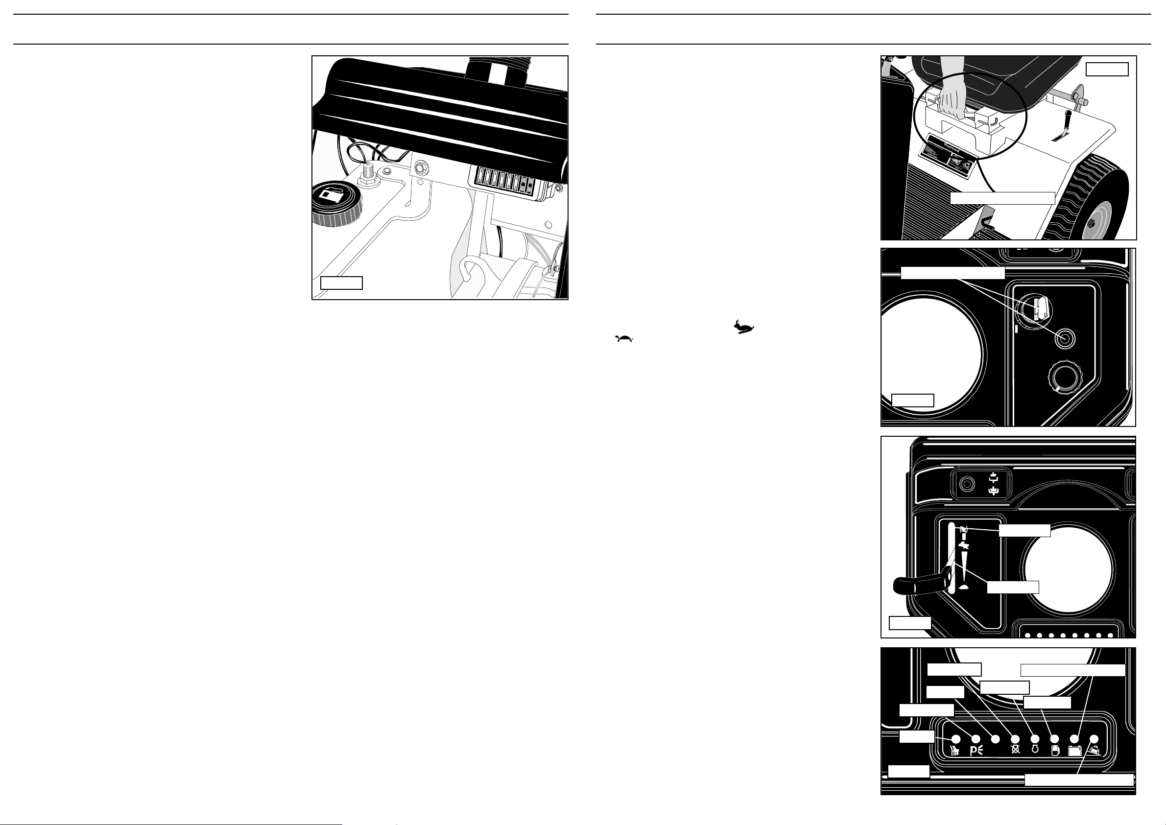
PGC Lift Lever (Fig 14)
Using the lever (figure 14) raise or lower the Powered
Grass Collector to either the Transport position or the
Collecting position. This lever is located on the right of the
driver on the S or T Series tractor and to the left of the
driver on the V20/50.
Power Take-Off - S/T Series (Fig 15)
To engage the PTO drive the PTO lever is lifted up out of
its locator moved to the left and released to find its own
height. To disengage the PTO pull the lever up and to the
right. Always have this lever in the ‘disengaged’ position
when it is not in use. DO NOT PUT HANDS NEAR
MOVING PULLEYS AND BELTS.
Power Take-Off - V20/50 (Fig 16)
To engage the PTO push the lever down and to the left
then release the lever upwards. The PTO lever is pushed
down and to the right into its locator to disengage. Always
have this lever in the ‘disengaged’ position when it is not
in use. DO NOT PUT HANDS NEAR MOVING PULLEYS
AND BELTS.
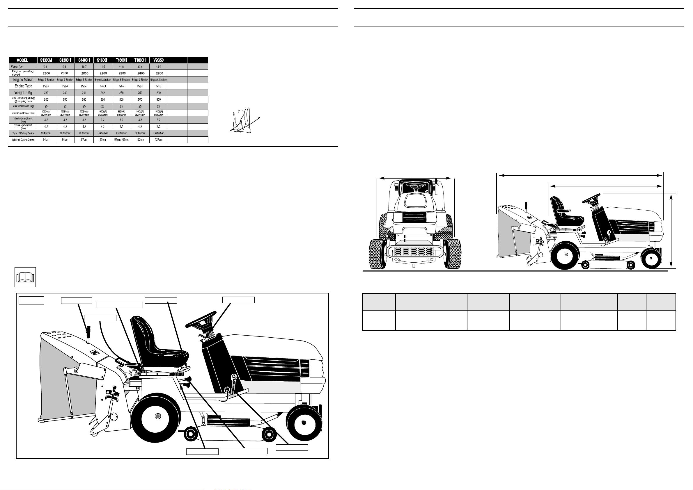
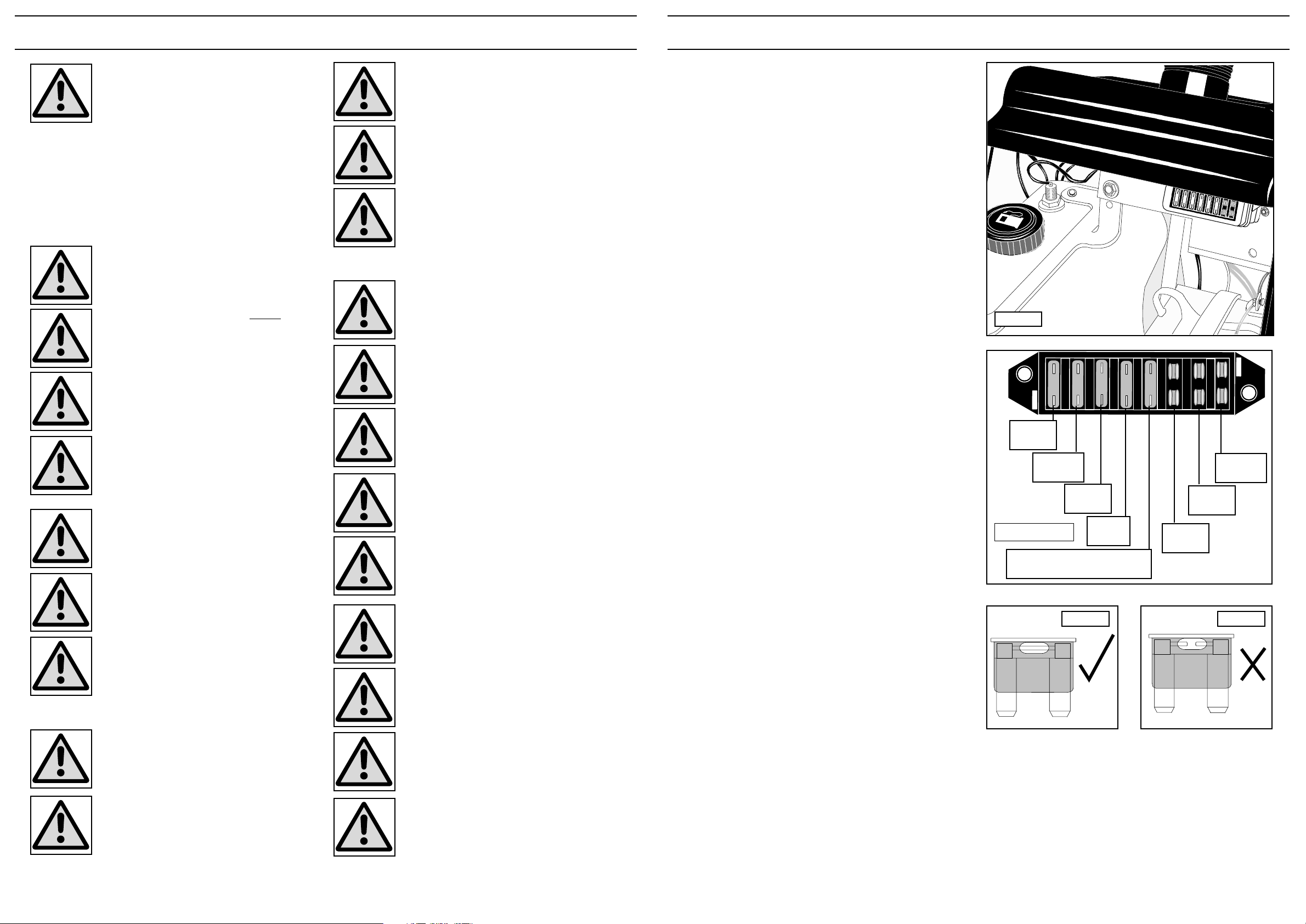
Lights (Fig 17)
Pressing the push button turns ON the headlights. Turn
the headlights OFF by pressing the button again.
The headlights will not operate without the ignition switch
turned on. NOTE: As an additional safety feature the
headlights will flash whilst the cutter deck is running
unless the lights are turned on.
RPM (Fig 5)
Your Westwood Tractor is equipped with an engine RPM
monitoring system to ensure that the correct engine speed
is maintained at all times. This consists of a green light
showing the engine is running above 2600 RPM which is
the minimum engine speed is recommended for good
grass cutting and collection. Below 2600 RPM the green
light will go out and a red one will illuminate next to it. If
during a mowing session the low RPM light comes on
then you must either raise the cutter deck or reduce your
mowing speed to allow the engine RPM to increase.
Electric Deck Lift (where fitted) -
(Figure 17)
The cutting height is adjusted by turning the rotary switch
anti-clockwise to lower the deck and clockwise to raise
the deck. The height indicator around the switch (Figure
17) shows the deck position (1-lowest to 10-highest).
To get the best from this refinement use it to continuously
adjust cutting height to suit ground and grass conditions.
Do not make downward adjustments on the move until
you are familiar with the height control this will avoid
“scalping” the lawn.
Page 17
DECK LEVEL SYSTEM FOR ‘S’ & ‘T’ SERIES
Tractors from serial No. 50104
Side to Side Level
This adjustment is best done with the deck in a position three up
from its lowest cut – check the level both sides and levelling is
then achieved by adjusting the left side (as you are sat on the
Tractor) of the deck at 2 points.
Rear Adjustment
Locate the top lock nut (A) and loosen this off using a 17mm
Spanner. Now wind the adjuster nut (B) either up or down using
a 19mm Spanner to alter the height of the deck on the left hand
side to match that on the right hand side. Use the marks on the
plate as a guide as to how much to raise or lower the deck.
When the deck is level at the rear tighten the lock nut securely
Front Adjustment
Locate the top lock nut (A) and loosen this off using a 17mm
Spanner. Now wind the adjuster nut (B) either up or down using
a 19mm Spanner to alter the height of the deck on the left hand
side to match that on the right hand side. Use the marks on the
plate as a guide as to how much to raise or lower the deck.
When the deck is level at the front tighten the lock nut securely.
Raise and then lower the cutter deck and then re-check the
level. If it is still incorrect re adjust as required
NOTE: 38, 44 and 0” Mulch decks must be set 10mm
higher at the front than the back
A
B
A
B
A
B
Manual Deck Lift
Electric Deck Lift
Front
Adjustment