WFI EKW FX10 User manual

GIMEKWFX-E November 2008
Installation Information
Water Piping Connections
Electrical
Startup Procedures
Troubleshooting
Preventive Maintenance
FX10 50 HZ HYDRONIC HEAT PUMPS
EKW FX10 Installation Manual

2
EKW FX10 INSTALLATION MANUAL
Model Nomenclature
EKW Series R-410A Hydronic Heat Pump (06 - 17 kW)
1-3 4-5 6 7 8 9 10-11 12
EKW 06 H 6 0 2 SS B
Family Vintage
EKW = E Series 50 hz B = Current
Hydronic Heat Pump
Non-Standard Options
Unit Capacity S = Standard
06 kW
A-R, T-Z = Nonstandard Options
08 kW
12 kW Control
17 kW 2 = Standard
4 = FX-10 without interface
Operation 5 = FX-10 with N2 card without interface
H = Heating Only 6 = FX-10 with LonWorks card without interface
R = Reversible 7 = FX-10 with BACnet card without interface
8 = FX-10 with MUI
Voltage 9 = FX-10 with N2 card and MUI
6 = 220-240/50/1 0 = FX-10 with LonWorks card and MUI
7 = 380-420/50/3 3 = FX-10 with BACnet card and MUI
A = Standard with IntelliStart *
Desuperheater (Requires accessory pump kit)
B = FX-10 without interface with IntelliStart *
0 = None C = FX-10 with N2 card without interface with IntelliStart *
2 = Hot Water Generation without D = FX-10 with LonWorks card without interface with IntelliStart *
Internally Mounted Pump ** E = FX-10 with BACnet card without interface with IntelliStart *
F = FX-10 with MUI with IntelliStart *
G = FX-10 with N2 card and MUI with IntelliStart *
H = FX-10 with LonWorks card and MUI with IntelliStart *
J = FX-10 with BACnet card and MUI with IntelliStart *
Notes:
* - Single Phase Only
** - Not available on 06

3
EKW FX10 INSTALLATION MANUAL
Table of Contents
General Installation Information.............................................4
Accessories & Other Options ................................................5
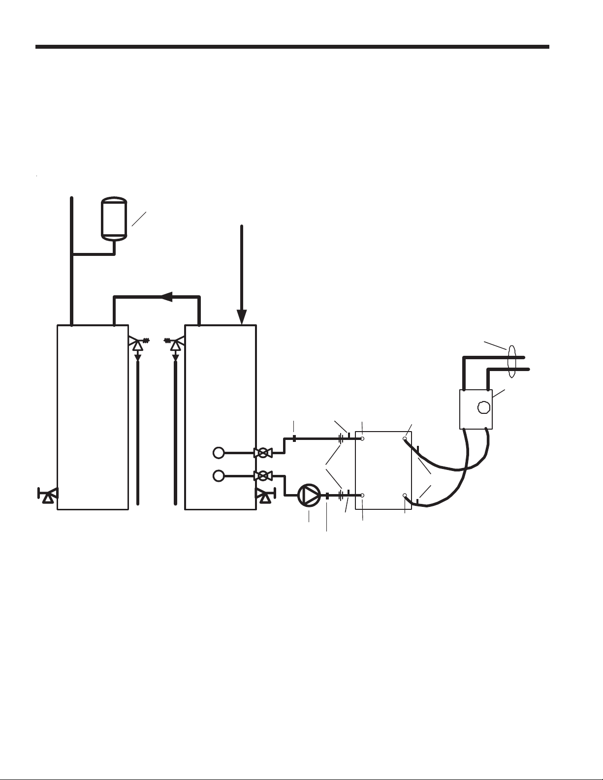
Potable Water Systems ......................................................6-7
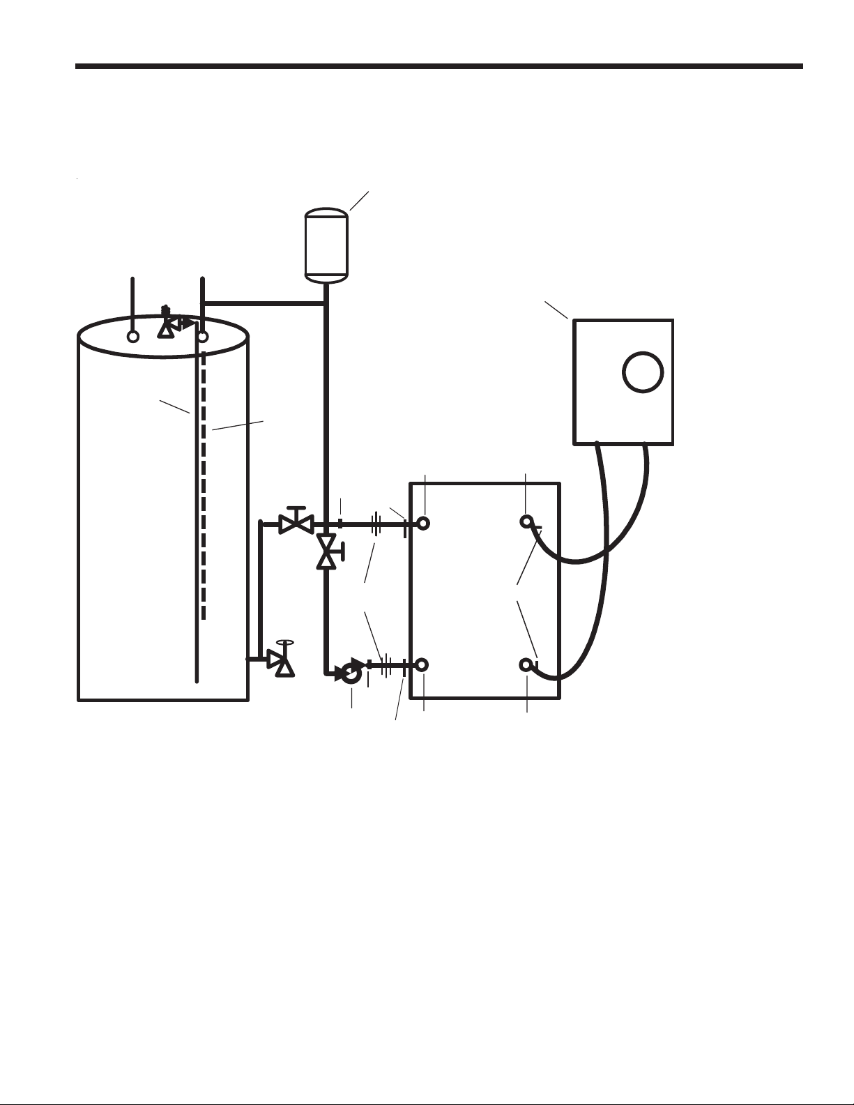
Open Loop Systems..............................................................8
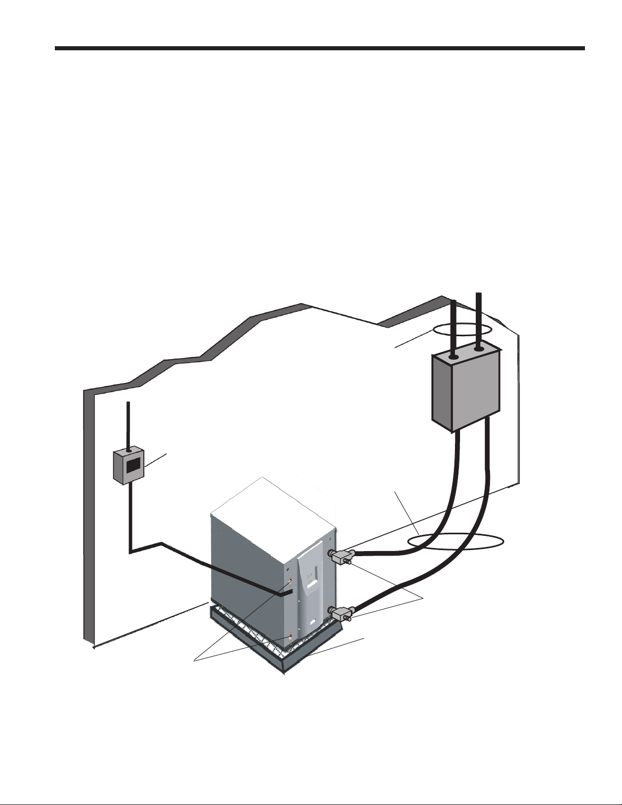
Earth Coupled Systems.........................................................9
Electrical..............................................................................10
Dimensional Data, Physical Elements, Sound Data............ 11
Electrical..............................................................................12
Small EKW Setup/Operation ..........................................13-14
1. Application Overview .......................................................15
2. Inputs and Outputs Conguration....................................15
3. Sequence of Operation....................................................16
3.1. Power Fail Restart.................................................16
3.2. Random Start Delay..............................................16
3.3. Compressor Fixed On Delay Time ........................16
3.4. Compressor Minimum On Delay ...........................16
3.5. Compressor Short Cycle Delay Time ....................16
3.6. Pump Sampling.....................................................16
3.7. Heating Cycle...................................................16-17
3.8. Cooling Cycle ........................................................17
3.9. Emergency Shutdown ...........................................17
3.10. Lockout Mode......................................................18
3.11. Entering Load Water Temperature (AI-1).............18
3.12. Leaving Load Water Temperature (AI-2) .............18
3.13. Entering Source Water Temp (AI-3) ....................19
3.14. Source Low Water Coil Temperature Limit (AI-4) .. 19
3.15. Load Low Water Coil Temperature Limit (AI-5) ...19
3.16. Entering Source Water Temp (AI-6) ....................19
3.17. Compressor Proving (BI-1)..................................19
3.18. Emergency Shutdown (BI-2) ...............................19
3.19. Low Pressure Switch (BI-3)................................19
3.20. Source Side Low Water Coil
Temperature Limit Select (BI-4)....................................19
3.21. Source Side Low Water Coil Temperature
Limit Selection (BI-5)....................................................19
3.22. Y1/System Enable Command (BI-7) ...................20
3.23. Source Flow Proving Switch (BI-8)......................20
3.24. Aqua-stat O/Heating-Cooling
Select Command (BI-9)................................................20
3.27. Load Flow Proving Switch (BI-12).......................21
4. Outputs............................................................................21
4.1. Reversing Valve (BO-1).........................................21
4.2. Compressor (BO-2)...............................................21
4.3. Reversing Valve (BO-3).........................................21
4.4. Secondary Unit Enable (BO-4)..............................21
4.5. Secondary Unit S-Plan Comfort Select
Enable (BO-5) ..............................................................21
4.6. Alarm Output (BO-6)..............................................21
4.7. Accessory Output 1/Source Pump
Control (BO-7)..............................................................22
4.8. Accessory Output 2/Load Pump
Control (BO-8)..............................................................22
Unit Startup..........................................................................23
ARI/ISO/BS EN Ratings ......................................................24
Capacity Data.................................................................25-40
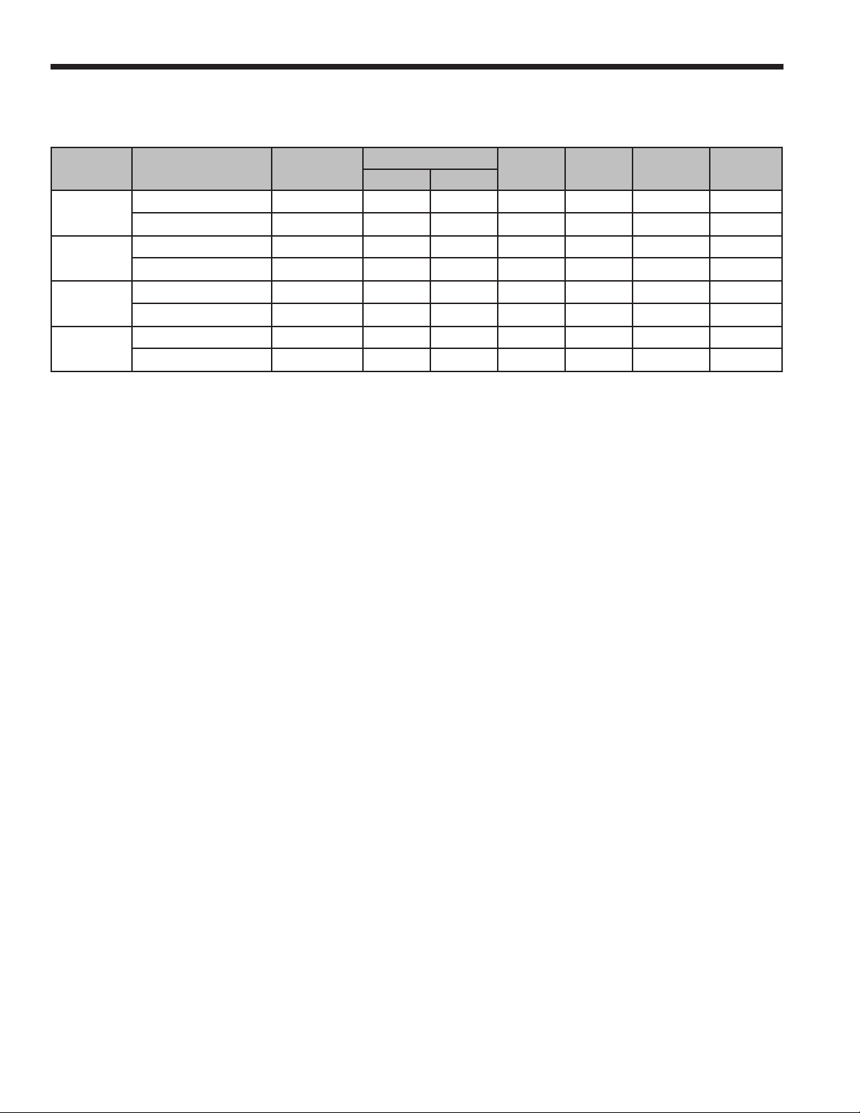
Source Flow Rates (L/s)......................................................41
Pressure Drop (kPa)............................................................41
Troubleshooting...................................................................42
Preventive Maintenance......................................................43
Disposal/Recycling Section .................................................44

EKW FX10 INSTALLATION MANUAL
Safety Advisements
Installation and servicing of heating and air conditioning equipment can be hazardous due to system pressure and electri-
cal components. Only trained and qualied service personnel should install, repair or service heating and air conditioning
equipment.
When working on heating and air conditioning equipment, observe precautions in the literature, tags and labels attached
to the unit as well as other safety precautions that may apply, such as the following safety measures:
Follow all safety codes.
•
Wear safety glasses and work gloves.
•
Use a quenching cloth for brazing operations.
•
Have a re extinguisher available for all brazing operations.
•
Moving and Storage
Move units in the normal “up” orientation. Do not stack more than two units in total height. When the equipment is
received, all items should be carefully checked against the bill of lading to be sure that all crates and cartons have been
received. Examine units from the cartons if necessary. Units in question should also be internally inspected. If any damage
is noted, the carrier should make the proper notation on the delivery receipt, acknowledging the damage.
Unit Location
Locate the unit in an indoor area that allows easy removal of the access panels and has enough space for service
personnel to perform maintenance or repair. Provide sufcient room to make water and electrical conditions. Units may be
stacked vertically in small mechanical rooms. These units are not approved for outdoor installation and, therefore, must be
installed inside the structure being conditioned. Do not locate in areas subject to freezing.
Piping
Both source as well as load uid piping must be at least as large as the unit connections on the heat pump (larger on long
runs).
Process Water Applications
For process water applications, it is recommended that a secondary load heat
exchanger be installed to prevent corrosion to the unit’s primary coaxial coil. In
situations where scaling could be heavy or where biological growth such as iron
bacteria will be present, a closed loop system is recommended. Over a period of
time, ground water unit heat exchanger coils may lose heat exchange capability
due to a buildup of mineral deposits. These can be cleaned only by a qualied
service mechanic as special pumping equipment and solutions are required. Never
use exible hoses with a smaller inside diameter than that of water connections.
Mounting Units
Units should be mounted level on a vibration absorbing pad slightly larger than
the base to provide isolation between the unit and the oor. It is not necessary
to anchor the unit to the oor. Allow access to front access panel for servicing
compressor.
Before performing service or maintenance operations on the system, disconnect all
power sources to unit. Electrical shock could cause personal injury. Before applying power to the
unit, make sure that all panels and screws are in place. Failure to do so could cause risk of electri
cal shock.
Vibration
Absorbing
Mesh Pad
Figure 1: Unit Mounting
Safety Considerations
General Installation Information

5
EKW FX10 INSTALLATION MANUAL
Accessories and Other Options
Desuperheater (Factory Installed, EKW08 to EKW17 only)
An optional heat reclaiming desuperheater coil constructed of vented double-wall copper construction suitable for
potable water is available. The coil is factory mounted inside the unit.
Load-side Pump Kit (Field Installed)
Load pump kits are available to provide all liquid ow requirements for independent single unit systems. To select the
proper pump, be certain that the system pressure drop is calculated correctly.
If the job requirements are outside the pump curve, an alternate pump will need to be obtained to maintain the
necessary ow.
Flow Rate GPM (L/s)
Feet of Head (kPa)
0 5
(0.32)
40 (119.6)
35 (104.7)
30 (89.7)
20 (59.8)
15 (44.9)
10 (29.9)
25 (74.8)
10
(0.63)
15
(0.95)
20
(1.26)
25
(1.58)
30
(1.89)
35
(2.21)
Flow Rate GPM (L/s)
Feet of Head (kPa)
0 2
(0.126)
20 (59.80)
15 (44.85)
10 (29.90)
5 (14.95)
4
(0.252)
6
(0.378)
8
(0.504)
10
(0.063)
12
(0.756)
14
(0.882)
16
(1.134v)
Figure 2: 24P501 - Pump Curve
Figure 3: EWPK1 - Pump Curve
Note: Never use piping smaller than
28 mm. Limit length of pipe to 16
meters or less.

EKW FX10 INSTALLATION MANUAL
Potable Water Systems
The EKW06 heating only model is designed to provide primary hot water generation. An optional factory-installed
desuperheater coil may be provided with an EKW08, 12 or 17 to assist in the generation of domestic hot water.
With either option, the coaxial heat exchangers provide double-wall construction and are vented to allow installation in
potable water applications. Figures 4 and 5 show how to connect a potable water system.
Figure 4: Suggested Domestic Water Heater Hookup
CO LD W AT E R
IN
H O T W A TE R
OUT
EL EC T R IC W A TE R
HEAT ER
HOT W A TE R
ST O R A G E
EQ U A L T O
A. O . S M IT H
TJ -8 0A
EW 0 2 0
HOT WATER
OUT
SOURCE
OUT
IN
EX PAN SI ON T A N K
IF R EQ UIR E D
PUMP
PT PORTS
PT PORTS
*UNIONS
(VALVES)
BOILER DRAIN
BOILER DRAIN
HOT WATER
OUT
PT PORTS
SOURCE
FLOW
CENTER
TO LOOP
FIELD
Unions or valves must be installed so that acid ushing of the heat exchanger is possible.
EKW06

EKW FX10 INSTALLATION MANUAL
Figure 5: Alternate Hot Water Installation
Potable Water Systems
* Unions or valves must be installed at the unit so acid ushing of the heat exchanger is possible.
** Make sure there is not a check valve in the diptube of the tank.
UNIONS *
(VALVES)
PT PORTS
PT PORTS
LOAD
IN
SOURCE
OUT
COLD
WATERIN
HOT
WATER OUT
FLOW
CENTER
ELECTRIC
WATER
H EATER
EKW06
Pump
SOURCE
IN
LOAD
OUT
EXPANSION TANK
IF REQUIRED
DIP TUBE **
P & T RELIEF TO
FLOOR DRAIN
BOILER DRAIN
BOILER
DRAIN
PT PORTS

8
EKW FX10 INSTALLATION MANUAL
Open Loop—Well Water Systems
Always maintain water pressure in the heat exchanger by placing water control valves at the outlet of the unit. Use a
closed bladder type expansion tank to minimize mineral deposits. Ensure proper water ow through the unit by checking
pressure drop across the heat exchanger and comparing it to the gures in the capacity data tables in the specication
catalog. Normally, about 0.042 L/s per kW of cooling capacity is needed in open loop systems, 0.032 L/s per kW minimum
if entering source temperature is above 50°F [10°C].
Some water control valves draw their power directly from the unit’s 24V transformer and can overload and possibly burn
out the transformer. Check total VA draw of the water valve(s) and ensure it is under 40 VA.
Discharge water from a heat pump can be disposed of in various ways depending on local building codes (i.e. recharge
well, storm sewer, drain eld, adjacent stream or pond, etc.). Most local codes restrict the use of sanitary sewer for disposal.
Consult your local building and zoning departments to ensure compliance in your area.
Desconexión
de la Tensión
en Línea
Conexiones para
Líquido de Carga
4ANQUEDE%XPANSIØN
&LEXIBLEDE'OMA
6ÉLVULADE2ETENCIØN
$RENAJEDELA#ALDERAPARA,AVADO
DEL)NTERCAMBIADORDE#ALOR
%NTRADADE!GUA
3ALIDADE!GUA
6ÉLVULA3OLENOIDE
6ÉLVULADE(AYES
4APONESPARA
#ONTROLDE
0RESIØNY
4EMPERATURA
6ÉLVULADE2ETENCIØN
PARAAISLARALAVÉLVULA
DESOLENOIDEMIENTRASSE
LAVACONÉCIDO
"ASEDE-ALLAODE!IREPARA!BSORBERLA6IBRACIØN
Figure 6: Typical Open Loop Installation

9
EKW FX10 INSTALLATION MANUAL
Earth-Coupled Systems with Flow Center
Once piping is completed between the unit, ow center and the earth loop, nal purging and charging of the loop is
needed. A ush cart (at least a 1.5 HP or 1.12 kW pump) is needed to achieve adequate ow velocity in the loop to purge
air and dirt particles from the loop itself. Antifreeze solution is used in most areas to prevent freezing. Maintain the pH in
the 7.6-8.2 range for nal charging.
Flush the system adequately to remove as much air as possible. Then, pressurize the loop to a static pressure of 50-75
psi [345-517 kPa]. This is normally adequate for good system operation. Ensure that the ow center provides adequate
ow through the unit by checking pressure drop across the heat exchanger and by comparing it to the gures shown in
the tables on page 36. Usually, 3 GPM/ton [0.054 L/s/kW] or minimum 2.25 GPM/ton [0.04 L/s/kW] of cooling capacity is
needed in closed loop earth-coupled applications.
Line Voltage
Disconnect
Earth-Coupled Loop
Piping with Insulation
Unit Connector Kits
with Insulation
Vibration Absorbing
Mesh or Air Pad
Load Liquid
Connections
P/T Plugs
Figure 7: Typical Closed Loop Earth-Coupled Installation

10
EKW FX10 INSTALLATION MANUAL
Electrical
Notes: All fuses are type “D” time delay (or HACR circuit breaker in USA).
Source pump amps shown are for up to 1/2 HP pump.
Load pump amps shown are for small circulators.
Unit
Model
Rated
Voltage
Voltage
Min/Max
Compressor Total Unit
FLA
Min Ckt
Amp
Max
Fuse
Max
Ckt Brk
RLA LRA
EKW06 220-240/50/1 198/264 10.9 58.0 10.9 13.6 20 20
380-420/50/3 342/462 4.5 26.0 4.5 5.6 10 10
EKW08 220-240/50/1 198/264 15.4 82.0 15.4 19.3 30 30
380-420/50/3 342/462 5.1 35.0 5.1 6.4 10 10
EKW12 220-240/50/1 198/264 21.1 136.0 21.1 26.4 45 45
380-420/50/3 342/462 7.7 51.0 7.7 9.6 15 15
EKW17 220-240/50/1 216/264 25.0 149.0 25.0 31.3 50 50
380-420/50/3 342/462 10.6 75.0 10.6 13.3 20 20
All fuses type “D” time delay.

11
EKW FX10 INSTALLATION MANUAL
*Test standard condition – BS EN 14511
(ARI 260)
PHYSICAL ELEMENTS
Unit
Model
A
in [mm]
B
in [mm]
C
in [mm]
Load
Liquid
in FPT in
Load
Liquid
out FPT in
Source
Liquid
out FPT in
Source
Liquid
in FPT in
Desuperheater
In FPT in
Desuperheater
Out FPT in
EKW06 25.5 [648] 26.3 [668] 18.0 [457] 0.75 0.75 0.75 0.75 - -
EKW08 32.5 [826] 26.3 [668] 22.0 [559] 1.00 1.00 1.00 1.00 0.50 0.50
EKW12 32.5 [826] 26.3 [668] 22.0 [559] 1.00 1.00 1.00 1.00 0.50 0.50
EKW17 32.5 [826] 26.3 [668] 22.0 [559] 1.00 1.00 1.00 1.00 0.50 0.50
DIMENSIONAL DATA
SOUND DATA
ALTERNATE WIRING
KNOCKOUT
Back View Front View
LOW VOLTAGE
PUMP WIRING
LINE VOLTAGE
SOURCE WATER IN
SOURCE WATER OUT
LOAD WATER IN
ALTERNATE
WIRING KNOCKOUT
LOAD WATER OUT
OPTIONAL
DESUPERHEATER
CONNECTION
TOUCH PAD
CONTROLLER
ALTERNATE WIRING
KNOCKOUT
ALTERNATE WIRING
KNOCKOUTS
ALTERNATE WIRING
KNOCKOUTS
OPTIONAL DESUPERHEATER
CONNECTION
A
C
B
Unit
Model Sound Rating*
EKW06 54 dBA
EKW08 56 dBA
EKW12 57 dBA
EKW17 58 dBA

12
EKW FX10 INSTALLATION MANUAL
Electrical
Be sure the available power is the same voltage and phase as that shown on the unit serial plate. Line and low voltage
wiring must be done in accordance with local codes or the National Electric Code, whichever is applicable. Refer to the Unit
Electrical Data on page 10 for wire and fuse or circuit breaker sizing information.
Flow Center Pump Operation
Two fuse internal terminal block connections with 1/4-inch spade connectors are provided; one for the load pump and
one for the source pump. The source pump directly connects to the fuse terminal block for the source pump. The load
pump directly connects to the fuse terminal block for the load pump.
Control Box Relocation
The control box can be installed on the rear of the unit. To relocate the control box, follow the procedures below.
Remove all power sources to the unit.1.
Remove the unit’s top panel.2.
Cut all plastic wire3. ties to the following:
a) High pressure switch (black wires)
b) Low pressure switch (blue wires)
c) Freeze protection (yellow wires)
d) Load temperature sensor (black wires)
e) Compressor wires
Remove the four screws from the control box.4.
Relocate the control box to opposite end of the unit.5.
Using the screws removed in step 4 above, reattach the control box.6.
Secure all wires so they do not come in contact with refrigerant lines.7.
Replace the top of the unit.8.
Replace both access panels.9.
Reapply power sources.10.

13
EKW FX10 INSTALLATION MANUAL
Small EKW Setup/Operation
Single compressor•
Reversible•
Setpoint or aquastat operation•
Single or duplexed load operation•
Stage-able in setpoint mode•
Extra(unused) IO is made available for optional use.•
Fault detection and compressor shutdown•
Fault history•
The default conguration-as shipped-is a reversible water-to-water heat pump ready for operation by ‘aquastat
calls’ to the terminal board (‘Y’ and ‘O’) or over the network. In the default conguration, ow switch inputs must be
connected to either ow switches or jumpers. In summary, if the specied power is applied, water ow at specied
ow rates and temperatures through the source and load heat exchangers, ow switch inputs connected, and connect
‘Y’ to ‘R’ on the terminal board—the unit will run.
Additional setup information.
If operation without ow switches is desired, the ‘Settings’ menu in the MUI allows selecting ‘Soft’ jumpers for the
Load and Source ow switch inputs. Setting these to the ‘Jumperd’ value allows the ow switch inputs to be used as
optional binary inputs to provide network information of accessory devices nearby.
Once the current revision is complete, the heat pump will operate in two set point modes. They will be identied as
‘Setpoint’ and ‘S-Plan’.
Setpoint Mode
In the ‘Setpoint’ mode, the controller is congured for operating a comfort heating/cooling load and a domestic hot
water load. The load switching is accomplished by energizing/de-energizing the ‘Load Water Valve’ output (BO-9). The
controller performs pump sampling operations at specied durations and intervals when the loads are satised, with
BO-9 switching between the loads. In the Setpoint mode, the controller operation is initiated is by presenting a ‘Y/Sys-
tem Enable’ call. This call may either be a terminal ‘Y’ to ‘R’ connection or a network command to the ‘ComprEnable’
variable. The comfort heat/cool operation is selected by using the ‘O’ call.
In the ‘S-Plan’ mode, the controller is congured for operating a comfort heating/cooling load and a domestic hot
water load. The controller performs pump sampling operations at specied durations and intervals when the loads are
satised. In the S-Plan mode, full setpoint operation is initiated is by presenting a ‘Y/System Enable’ call and a ‘POI’
call. This call may either be a terminal ‘Y’ to ‘R’ and ‘POI’ to ‘R’ connection or a network command to the ‘nviComprEn-
able’ and ‘nviPrimaryOvrd’ variables. In this manner, the controller will behave just as in the ‘Setpoint’ mode. If only
the ‘Y/System Enable’ call exists, the controller will act as a single-load setpoint controller for comfort heating and
cooling, energizing the Load Water Valve output. The comfort heat/cool operation is selected by using the ‘O’ call. If
only the ‘POI’ is enabled, the unit will operate as a heating-only setpoint controller with the Load Water Valve output
de-energized.

EKW FX10 INSTALLATION MANUAL
Fault Alarms
Load Flow
• [The ow switch on the load side is open concurrent with a compressor call]
Low Press
• [Low Suction Pressure Alarm]
Src Lo Temp
• [Formerly Src Freeze alarm]
Load Lo Temp
• [Formerly Load Freeze alarm]
Src Flow
• [The ow switch on the source side is open concurrent with a compressor call]
Hi Press
• [Hi Discharge Pressure on the compressor]
Bad Src Sensor
• [The sensor for ‘Src Low Temp is not within specied resistance limits]
Bad Ld Sensor
• [The sensor for ‘Ld Low Temp is not within specied resistance limits]
ChrgLoss
• [The controller was not seeing the low pressure switch prior to compressor start.
Hi Temp Limit
• [The Load Leaving Water temp was at or above 131°F [55°C]
The MUI
The MUI Home page displays the operating mode of the controller, the Load Entering Water temperature and
setpoint. The menu pages are seen at the bottom of the display. Since the length of the menu list exceeds the display
width of the MUI, the left/right arrow buttons may be used to scroll left or right in order to access the desired MUI
page. Once the desired page is in view, press the ‘Enter’ key once to activate the cursor, then use the left/right arrow
buttons to move the cursor to the desired item and press ‘Enter’ once again to select the page. The MUI menus are
depicted in the Tech Service FX10 Manual. Various parameters may be congured in the ‘Settings’ page and the
‘Maintenance’ page. On the Maintenance menu are:
‘Y1 Threshold’: the turn-on threshold of the rst stage, referencing the composite variable within the PID block. •
This variable is a degrees*seconds product.
‘Y2 Threshold’: the turn-on threshold of the second stage, referencing the composite variable within the PID block. •
This variable is a degrees*seconds product.
‘Load OnDly Time’ sets the minimum time spent looking at a satised load condition before moving on to the next load.•
‘CompStrtDly’ is the compressor start delay setting.•
‘HP Model’ allows eld switching from ‘Reversible’ to ‘Heating Only’.•
‘SrcFlowSw’ may either be ‘Normal’ or ‘Jumprd’ to act as a virtual jumper so that a wire jumper is not needed.•
‘LoadFlowSw’ may either be ‘Normal’ or ‘Jumprd’ to act as a virtual jumper so that a wire jumper is not needed.•
‘Y2 Td Thrshld’ sets the derivative error required to engage the Y2 call in the setpoint mode.•
‘Y1/Ena’ allows you to make a Y call from the MUI.•
‘RevValve’ allows you to make an O call from the MUI.•
‘PrimaryOvrd’ allows you to activate the POI input from the MUI.•
‘Dom Period’ the maximum length of a domestic water heating cycle.•
‘Comf Period’ the maximum length of a comfort heat/cool cycle.•
‘Dom Setpt’ domestic water setpoint.•
‘Htg Setpt’ Comfort heating setpoint•
‘Clg Setpt’ Comfort cooling setpoint•
‘Unit of Measure’ can select C and F for temperature readings.•
‘Pump Oper.’ Can be ‘Continuous’ or ‘Sampled’•
‘Sample Length’ sets the duration of a pump sampling operation.•
‘Y2 Clg Thrshld’ sets the actual temperature error required to engage the Y2 call in the setpoint mode in cooling.•
‘Y2 Htg Thrshld’ sets the actual temperature error required to engage the Y2 call in the setpoint mode in heating.•
‘Y2 On Delay’ sets the length of time that the Y2 temperature and time signal must remain to engage the call.•
The rst parameter can be set to ‘Aqua-stat Rev’ble’, ‘S-Plan’, or ‘Setpoint’•
The second parameter may be set to ‘Reversible’, or ‘Heating Only’.•

15
EKW FX10 INSTALLATION MANUAL
1. Application Overview
The application is created for an FX10 Universal Controller with no expansion board. The application is designed to
operate WaterFurnace E Series water–water heat pumps in either of three modes: Aqua-stat, S-Plan, or Setpoint.
The application will provide load entering water temperature setpoint control for comfort heating and cooling,
domestic hot water temperature setpoint control, and basic features such as a random start and anti-short cycle delay
for the compressor, low water coil temperature limit, safety switch sensing, and system fault lockout. The controller
will provide the following modes of operation: Aqua-stat Control, S-Plan, Setpoint Control, Emergency Shutdown, and
Lockout. The application will be designed for use with open N2, LON, and BACnet systems.
CS-SSWWE-01
REV B
E-Series Single Stage Water-to-Water
Controls Specification
Page 5 of 12
Created on 1/31/2007
5
3. Inputs and Outputs Configuration
SINGLE STAGE WW WITH STAGING
SETPOINT CONTROL
Input Name
Input
Location
Output Name
Output
Location
Entering Load Water Temperature
AI 1
Reversing Valve
BO1
Leaving Load Water Temperature
AI 2
Compressor Start/Stop
BO2
Entering Source Water Temperature
AI 3
Secondary Unit Heat/Cool
Select
BO3
Source low water coil temperature limit
Protection
AI 4
Secondary Unit Enable (Y2)
BO4
Load low water coil temperature limit
Protection
AI 5
Secondary Unit S-Plan Comfort
Select Enable
BO5
Leaving Source Water Temperature
AI 6
Alarm
BO6
Accessory Output 1/Src Pump
BO7
Compressor Proving
BI 1
Accessory Output 2/Load Pump
BO8
Emergency Shutdown
BI 2
Load Water Valve Control
B09
Low Suction Pressure Switch
BI 3
Source Low Temp Limit Select - 30ºF/-1°C
BI 4
Unused
PWM1
Load Low Temp Limit Select - 30ºF/-1C°
BI 5
Unused
PWM2
Spare
BI 6
Y1/System Enable
BI 7
Source Flow Proving
BI 8
Aqua-stat O/Heating-Cooling select
BI 9
S-Plan Comfort Select
B10
Stage 1 High Pressure
BI11
Load Flow Proving
BI12
XP10 Expansion Card
Input Name
Input
Location
Output Name
Output
Location
Unused
AI 1
Unused
BO 1
Unused
AI 2
Unused
BO 2
Unused
AI 3
Unused
BO 3
Unused
AI 4
Unused
BO 4

EKW FX10 INSTALLATION MANUAL
3.1. Power Fail Restart
When the controller is rst powered up, the outputs will be disabled for a random start delay time (See Section
3.2). The delay is provided to prevent simultaneous starting of multiple heat pumps. Once the timer expires, the
controller will operate normally. A restart status variable is available for indication of this occurrence.
3.2. Random Start Delay
This delay will be used after every power failure, as well as the rst time the compressor is started after the
control exits the emergency shutdown mode. The default time period for the start delay will be random between 1
and 120 seconds.
3.3. Compressor Fixed On Delay Time
The Compressor Fixed On Delay Time will ensure that the compressor output (B02) is not enabled for (30)
seconds after the control receives a call to start the compressor. This call may originate from an Aqua-stat or from
the internal setpoint control logic.
The compressor minimum on delay will ensure that the compressor output is enabled for a minimum of (2)
minutes each time the compressor output is enabled. This will apply in every instance except in the event the
high pressure switch is tripped or emergency shutdown, which causes the compressor output to be disabled
immediately.
3.5. Compressor Short Cycle Delay Time
The compressor short cycle time delay will ensure that the compressor output will not be enabled for a
minimum of (5) minutes after it is disabled. This allows for the system refrigerant pressures to equalize after the
compressor is disabled.
The load water pump may be set to operate in either Sampled or Continuous mode. In the Continuous mode,
the load pump will run any time unit operation is enabled, both in Setpoint mode and S-Plan. In the Sampled
mode, the load pump will run during all compressor calls, and will cycle in a user-adjustable fashion when no
compressor calls exist, in order to allow a determination of the need to run the compressor. In a domestic cycle,
a pump sample period is 1/2 of the domestic operation cycle length. In a comfort cycle, the sample period is 1/2
of the comfort operation cycle length. The sample length is 200 seconds initially, and is adjustable. In the nal 60
seconds of a sample operation, the temperature control logic is allowed to generate a compressor call if indicated
by the temperature/setpoint relationship. Sampling does not apply to Aqua-Stat mode of operation.
During the heating cycle, the reversing valve will be positioned for heating operation. The compressor
will be cycled in response to the load entering water temperature/setpoint control logic. Accessory output 2
will be commanded on 60 seconds prior to compressor start and remain on for a delay of 30 seconds after
the compressor is turned off-suitable for load loop pump operation. Accessory output 2 is network and MUI
congurable to run continuous if either the Y1/System Enable input or the S-Plan input is active or cycled
operation. Accessory output 1 is cycled to operate with the compressor, suitable for source loop pump
operation. Compressor operation will be time-shared in order to maintain setpoint temperature in a domestic
hot water tank and setpoint temperature in a heating water loop suitable for in-oor radiant heating. Primary
consideration is given to the domestic hot water. A domestic hot water heating cycle will end once the set-
point is reached, or after an adjustable time delay has expired. At the end of a domestic water heating cycle,
the position of the load water valve will be changed via BO-9 and a heating cycle for the comfort heating
water loop will begin. If the heating water loop entering water temperature is within setpoint requirements, the
controller immediately switches to domestic hot water operation. After the compressor output is turned off, it
will remain off for the time specied in the compressor short cycle time delay.

EKW FX10 INSTALLATION MANUAL
This mode allows externally selectable separate operation of domestic hot water or comfort conditioning.
If only the Y1/System Enable input (BI-7) is enabled, the heat pump will only operate for the domestic hot
water load. If the S-Plan Select Enable/POI (BI-10) is enabled and the Y1/System Enable input (BI-7) is not
enabled, the reversing valve will be positioned for heating and the heat pump will only operate for the comfort
heating. Compressor operation will be setpoint controlled based on the relationship of the load entering water
temperature and the setpoint. If both the Y1/System Enable (BI-7) and S-Plan Comfort Select Enable (BI-10)
are enabled, during the heating cycle, the reversing valve position will remain in the heating position. Com-
pressor operation will be time-shared in order to maintain setpoint temperature in a domestic hot water tank
and setpoint temperature in a chilled water loop suitable for fan coil cooling operation. Primary consideration
is given to the domestic hot water. A domestic hot water heating cycle will end once the setpoint is reached,
or after an adjustable time delay has expired. At the end of a domestic water heating cycle, the position of the
load water valve will be changed via BO-9, and a sampling period will begin for determining comfort heating
needs. If comfort heating is required, the reversing valve will remain positioned for heating and a comfort
heating cycle will begin. If the heating water loop entering water temperature is within setpoint requirements,
the controller switches to domestic hot water operation after a sampling delay. The compressor will be cycled in
response to the load entering water temperature/setpoint control logic. Accessory output 2 (X2) will be com-
manded on 60 seconds prior to compressor start and remain on for a delay of 30 seconds after the compressor
is turned off-suitable for load loop pump operation. Accessory output 2 is network and MUI congurable to run
continuous if the Y1/System Enable input is activated, or cycled. After the compressor output is turned off, it will
remain off for the time specied in the compressor short cycle time delay. Accessory Output 1 (X1) is cycled
with the compressor, suitable for source loop pump operation.
During the heating cycle, the reversing valve will be positioned for heating operation. If an aqua-stat
is being used, the aqua-stat will command the reversing valve “Off” on a call for heating. When a Y call is
initiated, and the random restart delay timer is expired, accessory output 2 will turn on. If the compressor
short cycle time delay has been satised, the compressor and accessory output 1 will turn on after the xed
compressor start delay timer has been satised. When heating is no longer required, the compressor and
accessory output 1 will be turned off immediately after the compressor minimum on delay has been satised.
After the compressor output is turned off, it will remain off for the time specied in the compressor short cycle
time delay. Accessory output 2 will be turned off 30 seconds after the compressor stops.
3.8. Cooling Cycle
3.8.1. Setpoint Mode
During the cooling cycle, the reversing valve position will be controlled by the internal temperature setpoint
control logic. Compressor and reversing valve operation will be time-shared in order to maintain setpoint
temperature in a domestic hot water tank and setpoint temperature in a chilled water loop suitable for fan coil
cooling operation. Primary consideration is given to the domestic hot water. A domestic hot water heating
cycle will end once the setpoint is reached, or after an adjustable time delay has expired. At the end of a
domestic water heating cycle, the position of the load water valve will be changed via BO-5, and a sampling
period will begin for determining comfort cooling needs. If cooling is required, the reversing valve will
positioned for cooling and a cooling cycle will begin. If the chilled water loop entering water temperature is
within setpoint requirements, the controller switches to domestic hot water operation after a sampling delay.
The compressor will be cycled in response to the load entering water temperature/setpoint control logic.
Accessory output 2 will be commanded on 60 seconds prior to compressor start and remain on for a delay of
30 seconds after the compressor is turned off-suitable for source loop pump operation. Accessory output 2 is
network and MUI congurable to run continuous if the Y1/System Enable input is activated, or cycled opera-
tion. After the compressor output is turned off, it will remain off for the time specied in the compressor short
cycle time delay.

18
EKW FX10 INSTALLATION MANUAL
This mode allows externally selectable separate operation of domestic hot water or comfort conditioning.
If only the Y1/System Enable input (BI-7) is enabled, the heat pump will not enter cooling mode. If the S-Plan
Select Enable (BI-10) is enabled and the Y1/System Enable input (BI-7) is not enabled, the reversing valve
will be positioned for cooling. Compressor operation will be setpoint controlled based on the relationship of
the load entering water temperature and the setpoint. If both the Y1/System Enable (BI-7) and S-Plan Comfort
Select Enable (BI-10) are enabled, during the cooling cycle, the reversing valve position will be controlled
by the ’O’ input and the domestic/comfort cycle status. Compressor and reversing valve operation will be
time-shared in order to maintain setpoint temperature in a domestic hot water tank and setpoint temperature
in a chilled water loop suitable for fan coil cooling operation. Primary consideration is given to the domestic
hot water. A domestic hot water heating cycle will end once the setpoint is reached, or after an adjustable
time delay has expired. At the end of a domestic water heating cycle, the position of the load water valve
will be changed via BO-9, and a sampling period will begin for determining comfort cooling needs. If cool-
ing is required, the reversing valve will positioned for cooling and a cooling cycle will begin. If the chilled
water loop entering water temperature is within setpoint requirements, the controller immediately switches
to domestic hot water operation. The compressor will be cycled in response to the load entering water
temperature/setpoint control logic. Accessory output 2 will be commanded on 60 seconds prior to compressor
start and remain on for a delay of 30 seconds after the compressor is turned off-suitable for load loop pump
operation. Accessory output 2 is network and MUI congurable to run continuous if the Y1/System Enable
input is activated, or cycled. After the compressor output is turned off, it will remain off for the time specied in
the compressor short cycle time delay After the compressor output is turned off, it will remain off for the time
specied in the compressor short cycle time delay. Accessory output 1 is cycled with the compressor, suitable
for source loop pump operation.
During the cooling cycle, the reversing valve will be positioned for cooling operation. If an aqua-stat is
being used, the aqua-stat will command the reversing valve “On” for cooling. When a Y call is initiated, and
the random restart delay timer is expired, accessory output 2 will turn on. If the compressor short cycle time
delay has satised, the compressor and accessory output 1 will turn on after the xed compressor start delay
timer has been satised. When cooling is no longer required, the compressor and accessory output 1 will
be turned off immediately after the compressor minimum on delay has been satised. After the compressor
output is turned off, it will remain off for the time specied in the compressor short cycle time delay. Acces-
sory output 2 will be turned off 30 seconds after the compressor stops.
3.9. Emergency Shutdown
The emergency shutdown mode can be activated by a command from a facility management system or a
closed contact on BI-2. The default state for the emergency shutdown data point is off. When the emergency
shutdown mode is activated, all outputs will be turned off immediately and will remain off until the emergency
shutdown mode is de-activated. The rst time the compressor starts after the emergency shutdown mode has
been de-activated, there will be a random start delay present.
3.10. Lockout Mode
Lockout mode can be activated by any of the following fault signals: compressor high discharge pressure,
compressor low suction pressure, low water coil temperature limit on the evaporator, and low water ow on either
the source or load sides of the unit. When any valid fault signal remains continuously active for the length of its
recognition delay, the controller will go into fault retry mode, which will turn off the compressor. After the Compres-
sor short cycle delay, the compressor will attempt to operate once again. If three consecutive faults are recognized
in 60 minutes, the unit will go into lockout mode, turning off the compressor and enabling the alarm output until the
controller is reset. The lockout condition can be reset by powering down the controller, by a command from the
facility management system, or through a user interface.
The entering load water temperature sensor will measure the entering water temperature on the load side of
the heat pump. By default, in the setpoint mode, compressor operation is cycled in response to the entering load
water temperature and setpoint relationship.

19
EKW FX10 INSTALLATION MANUAL
The leaving load water temperature sensor will measure the leaving water temperature on the load side of the
heat pump. A eld selectable option is available to select compressor operation in response to the leaving load
water temperature and setpoint relationship.
The leaving source water temperature sensor will measure the leaving water temperature on the source side
of the heat pump.
The source low water coil temperature limit temperature sensor will monitor the liquid refrigerant temperature
leaving the condenser. If the temperature drops below the source low water coil temperature limit trip point for the
recognition delay period, the condition will be recognized as a fault. The source low water coil temperature limit
trip point will be factory set for 30°F [-1ºC] and will be eld selectable for 15°F [-9ºC] by removing a jumper wire on
BI-9. The source low water coil temperature limit fault condition will be bypassed 2 minutes at normal compressor
startup, to allow the refrigeration circuit to stabilize.
The load low water coil temperature limit temperature sensor will monitor the liquid refrigerant temperature
leaving the condenser. If the temperature drops below the load low water coil temperature limit trip point for the
recognition delay period, the condition will be recognized as a fault. The load low water coil temperature limit trip
point will be factory set for 30°F [-1ºC] and will be eld selectable for 15°F [-9ºC] by removing a jumper wire on
BI-10. The load low water coil temperature limit fault condition will be bypassed 2 minutes at normal compressor
startup, to allow the refrigeration circuit to stabilize.
The entering source water temperature sensor will measure the entering water temperature on the source side
of the heat pump.
The compressor proving input shall be a N.O. input that will monitor the operation of the compressor.
The emergency shutdown mode can be activated by a command from a facility management system or a
closed contact on BI-2. The Default State for the emergency shutdown data point is off. When the emergency
shutdown mode is activated, the compressor will be turned off immediately and will remain off until the emergency
shutdown mode is de-activated. The rst time the compressor starts after the emergency shutdown mode has
been de-activated; there will be a random start delay present.
The low-pressure switch shall be a normally closed (N.C.) switch that monitors the systems refrigerant pres-
sure. The input shall be checked 15 seconds before compressor start up to be sure the pressure switch is closed
and then ignored for the rst 2 minutes after the compressor output (BO-2) is enabled. If the switch is open
continuously for (30) seconds the compressor output (BO-2) will be disabled. The compressor will not restart until
the compressor short cycle time delay has been satised.
The source side low water coil temperature limit selection input allows you to adjust the source side low water
coil temperature limit set point (AI-4). When the jumper is installed on BI-4 the source side low water coil tempera-
ture limit set point is factory set for 30°F [-1ºC]. When you remove the jumper on BI-9 the source side low water
coil temperature limit set point will be 15°F [-9ºC].
The load side low water coil temperature limit selection input allows you to adjust the load side low water coil
temperature limit set point (AI-5). When the jumper is installed on BI-5 the load side low water coil temperature
limit set point is factory set for 30°F [-1ºC]. When you remove the jumper on BI-10 the load side low water coil
temperature limit set point will be 15°F [-9ºC]

20
EKW FX10 INSTALLATION MANUAL
This input is mapped to the network variable nvoBI-6 to allow network status monitoring of additional devices.
The Y1/System Enable command input shall be used to wire a 24 VAC “Y1” input from an aqua-stat and
will control the operation of the compressor output (BO-2).
3.23.2. Setpoint Mode
The Y1/System Enable command input shall be used to wire a 24 VAC “Y1” input from an external manual
switch or relay and will enable the FX10 to perform temperature setpoint control of the entering load water
temperature by compressor operation.
The Y1/System Enable command input shall be used to wire a 24 VAC “Y1” input from an external contact
and will enable the FX10 to perform the heating-only function of domestic hot water temperature control. The
setpoint is compared to the load entering water temperature.
The source ow proving switch shall be a normally open ow switch that will close when the water ow
through the source side heat exchanger reaches an acceptable level. The source ow proving switch must be
closed 15 seconds prior to enabling the compressor output (BO-2). If the source ow proving switch opens
at any time the compressor output (BO-2) must be disabled immediately. Once the ow switch has opened
the alarm output will be energized after a 5 minute delay time. If the ow switch closed at any time after it has
been sensed open the fault will clear and the unit will return to normal operation.
The aqua-stat O/Heating-Cooling Select command input shall be used to wire a 24 VAC “O” input from an
aqua-stat and will control the operation of the reversing valve output (BO-1).
3.25.2. Setpoint Mode
The aqua-stat O/Heating-Cooling Select command input shall be used to wire a 24 VAC “O” input from an
external switch or relay and will control the operation of the reversing valve output (BO-1) as well as condi-
tioning the temperature setpoint control logic for either heating or cooling. An absence of the 24 VAC signal
on BI-9 is a heating mode command.
In the S-Plan mode, an enable signal on BI-10 causes the controller execute the heating and cooling algo-
rithms to maintain load entering water temperature at the comfort setpoint.
The high-pressure switch shall be a normally closed (N.C.) switch that monitors the systems refrigerant
pressure. The input will not be monitored until the compressor output (BO-2) is enabled. If the input senses the
high-pressure switch is open during the period that the compressor output (BO-2) is enabled, it must shut down the
compressor immediately and count the fault. The compressor minimum on time does not apply if the high-pressure
switch trips. The compressor will not restart until the compressor short cycle time delay has been satised.
Table of contents
Other WFI Heat Pump manuals
Popular Heat Pump manuals by other brands

Trane
Trane GEH/V Series installation instructions

Ruud
Ruud SON Series Installation, operation and service manual

Heat Controller
Heat Controller VMH 09 installation manual

Carrier
Carrier 38SQ100 Installation, Start-Up and Service Instructions

Jandy
Jandy JRT Series Installation and operation manual

Sime
Sime ECOMAXI 90 ErP manual