Whale 1247-5100-TC User manual

INSTALLATION AND OPERATION MANUAL - USA
Wh le® Electric Touch Control Cooktops
Note – Keep these instructions for loc l electric l inspector’s use.
Model Number Description
1247-5100-TC
2247-5100-TC
3247-5100-TC
1, 2 & 3 Burner Touch Control Electric Cooktops 120V
Pencil Edging
1247-5200-TC
2247-5200-TC
3247-5200-TC
1, 2 & 3 Burner Touch Control Electric Cooktops 240V
Pencil Edging
1247-5400-TC
2247-5400-TC
3247-5400-TC
1, 2 & 3 Burner Touch Control Electric Cooktops 208V
Pencil Edging
G1247-5100-TC
G2247-5100-TC
G3247-5100-TC
1, 2 & 3 Burner Touch Control Electric Cooktops 120V
Bevelled Edging
G1247-5200-TC
G2247-5200-TC
G3247-5200-TC
1, 2 & 3 Burner Touch Control Electric Cooktops 240V
Bevelled Edging
G1247-5400-TC
G2247-5400-TC
G3247-5400-TC
1, 2 & 3 Burner Touch Control Electric Cooktops 208V
Bevelled Edging

ENG
Ple se note: Whale recommends that a qualified technician must install and ground this
product. Whale accepts no responsibility or liability for damage to equipment, injury, or
death that may result from improper installation or operation of this product. When using
electrical appliances, basic safety precautions to reduce the risk of fire, electrical shock,
or personal injury to persons must be followed.
Prior to inst ll tion, ensure ll electric supply is turned off.
1. This appliance is designed only for indoor use on a leisure vessel or recreational vehicle. t is
the user's responsibility to ensure that the appliance is suitable for any other intended use.
2. Never use this appliance for warming or heating a room.
3. Electric only - Not suitable for use with firelighters, flammable liquids, diesel or chemicals.
4. Flammable materials (such as gas canisters) must not be stored near to the appliance.
5. n the event of a grease fire, do not use water – smother the fire or flame or use a dry
chemical / foam type extinguisher. Whale recommends keeping the correct fire extinguisher on
your vessel or vehicle as a safety precaution.
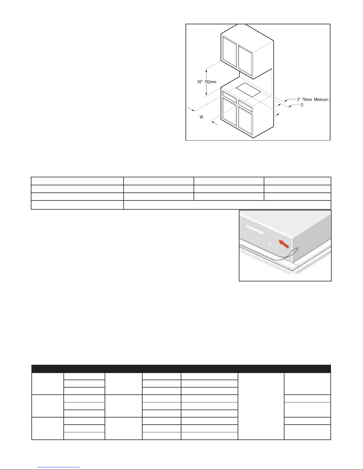
6. To eliminate the risk of burns or fire by reaching across heated surface units, cabinet storage
space located above the surface units should be avoided. f the cabinet storage must be
located above the appliance. Whale recommends installing a range hood that projects
horizontally a minimum of 5” (127mm) beyond the bottom of the cabinets (see section 10).
7. Never leave the appliance unattended while in use, as pan contents may boil over causing
smoking and potential grease fires.
8. Never leave the appliance unattended when in use. This appliance is not intended for use by
persons (including children) with reduced physical, sensory or mental capabilities, or lack of
experience and knowledge, unless they have been given supervision or instruction concerning
use of the appliance by a person responsible for their safety. Children must be supervised to
ensure that they do not play with the appliance. Never allow anyone to sit or stand on any
part of the unit.
9. C ution - Do not store items of interest to children in units surrounding this appliance as
children climbing onto units could be injured.
10. Appropriate apparel is required for using this product. Loose fitting or hanging garments
must not be worn while using this appliance.
11. Ensure that the appliance, pot holders and utensils are fully dry before use. Water on the
surface may heat when in use and create a steam that could burn.
12. To reduce the risk from burns, ignition of flammable materials, and spillage due to unintentional
contact with the utensil, the handle of a utensil should be positioned so that it is turned inward,
and does not extend over adjacent hot surfaces.
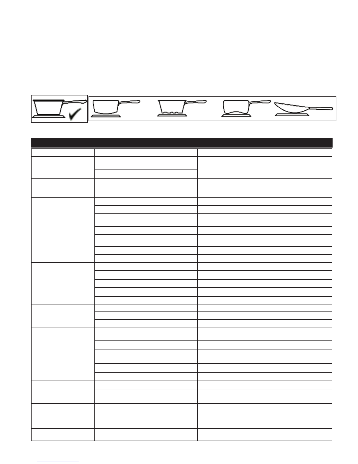
13. Properly sized pans must be used with this appliance. Oversized pans will cause heat
damage to your appliance and undersized pans will expose a portion of the heating element
allowing direct contact which can result in ignition of clothing.
14. Only certain types of glass, glass/ceramic, ceramic, earthenware or other glazed utensils are
suitable for range-top service without breaking due to sudden change in temperature.
1. WARN NG - MPORTANT NSTRUCT ONS
INSTALLATION AND OPERATION MANUAL
Wh le® Electric Touch Control Cooktop
Thank you for purchasing this Whale® product. For over 30 years, Seaward Products has manufactured high quality water
heating, cooking and gas supply products. The company has now been taken over by Whale, who has led the way in the
design and manufacture of water systems including freshwater, bilge, gray and black waste management, faucets,
showers, plumbing and accessories in the marine and RV industries for the past 60 years. Whale’s products are built on a
reputation for quality, reliability and innovation backed up by excellent customer service. For more information please visit
www.whalepumps.com/marine
NSTALLAT ON & USER NSTRUCT ONS

*Available in portrait with suffix ‘-AC’. Dimensions are 21” x 12” x 2 1/4” (535mm x 305mm x 58mm)
1. WARN NGS 10. NSTALLAT ON
2. SPEC F CAT ON 11. NSTRUCT ONS FOR USE
3. CONTENTS AND D AGRAMS 12. TROUBLE SHOOT NG
4. PR NC PLES OF OPERAT ON 13. MA NTENANCE
5. TO THE USER 14. SERV CE SUPPORT DETA LS
6. TO THE F TTER 15. PATENTS/ TRADEMARKS
7. APPL CAT ON 16. WARRANTY STATEMENT
8. PARTS L ST
9. OPT ONAL EXTRAS
LIST OF DIAGRAMS:
Figure 1A - 1C -Sea Rail and Potholder Layout Figure 2 - Appliance Location
Figure 3 - Securing The Appliance Figure 4 - Wiring Diagram
Figure 5 - nstructions For Use Figure 6 - Cooking Vessel Recommendations
The Whale® Touch Control Cooktop is designed for use in marine vessels or recreational vehicles for indoor use only. The
cooktop is operated by touching the symbols on the glass surface providing a smooth unobstructed surface for ease of
cleaning. Each cooking zone has eight temperature settings and an automatic shutdown for safety. Please refer to the
Specifications (Section 2) for the range of models.
2. SPEC F CAT ON
Product Code 1247-5100 1247-5400 1247-5200 2247-5100* 2247-5400* 2247-5200* 3247-5100 3247-5400 3247-5200
Edge Style Pencil Edging (For Bevelled Edging add ‘G’ prefix before code)
Elements 1 2 3
Voltage, AC 120V 208V 240V 120V 208V 240V 120V 208V 240V
Power 1200W 2400W 3600W
Recommended
Breaker Size 15A 10A 10A 25A 15A 15A 35A 20A 20A
Current Draw 10A 7.8A 5A 20A 11.5A 10A 30A 17.3A 15A
Orientation n/a Landscape* Landscape
Dimensions
(wxdxh)
13” x 13” x 2 1/4”
(331mm x 331mm x 58mm)
22” x 13” x 2 1/4”
(559mm x 331mm x 58mm)
22” x 20” x 2 1/4”
(559mm x 508mm x 58mm)
Cut Out Size
(wxdxh)
12 3/8” x 12 3/8” x 5 1/4”
(315mm x 315mm x 134mm)
21 3/8” x 12 3/8” x 5 1/4”
(543mm x 315mm x 134mm)
21 3/8” x 19 3/8” x 5 1/4”
(543mm x 493mm x 134mm)
Weight 10lbs (4.6kg) 18lbs (8.2kg) 29lbs (13.2kg)
Finish Glass Ceramics and White Graphics
3. L ST OF CONTENTS AND L ST OF D AGRAMS
4. PR NC PLES OF OPERAT ON
15. Do not cook on a broken cooktop as cleaning solutions and spillovers may penetrate the
broken cooktop and create a risk of electric shock. Contact a qualified technician immediately.
16. Do not heat unopened food containers. Build-up of pressure may cause containers to burst
and result in injury.
17. Do not touch appliance or surrounding surface until it has fully cooled down.After use, the
appliance and utensils used may still be hot to touch even if the units are dark in colour.
Depending on installation, working surfaces near to the appliance may also heat up during
use. Allow the appliance and surrounding area to fully cool before touching, cleaning or
allowing flammable material (e.g. clothing) to come in contact with the area.
18. Clean the appliance cooktop with caution. f a wet sponge or cloth is used to wipe spills on a
hot cooking area, be careful to avoid steam burn. Some cleaners can produce noxious fumes
if applied to a hot surface.Do not use a bulky towel or cloth to wipe up spills while the
appliance is in use - this can result in the material catching fire causing injury.
19. Do not repair or replace any part of this appliance unless specifically recommended in the
instructions manual. NOTE All servicing should be referred to a qualified technician.
20. WARNING: Fire hazard. Wiring must comply with applicable electrical standards and include
a properly sized fuse or circuit breaker. mproper wiring can cause a fire resulting in injury or
death. Switch off the power while making connections. Suggested wiring information is given
as guidance only. For full information, refer to the USCG, ABYC and SO regulations for
marine applications and wiring gauges, connectors and fuse protection.

Read the following carefully before installation and p y p rticul r ttention to the W rnings, Section 1.
WARNING: Please note that incorrect installation may invalidate the warranty.
Check that the product is suitable for the intended application, follow these installation instructions and ensure all relevant
personnel read the points listed below. Also ensure that these operating instructions are passed on to the end user.
NOTE: Keep these instructions for local inspector’s use.
Whale® Touch Control Cooktops are designed for use in recreational marine vessels or recreational vehicles only and
operated on AC electrical supply only. f it is intended for any other purpose it is the user's responsibility to ensure that
the appliance is suitable for the intended use.
1 x Cooktop
Figure 1 - Sea Rail and Pot Holder Layout - Plan view
NOTE: ncorrect installation will invalidate warranty and may cause injury or death.
Preparation - Always disconnect power sources before installing.
Ensure your appliance is properly installed and grounded by a qualified electrician.
10.i Loc tion
• Ensure the appliance is installed in a well ventilated area.
• Ensure the product is accessible for maintenance - nstall this product only in accordance with the provided
installation instructions.
10. NSTALLAT ON
8. APPL CAT ON
9. PARTS L ST
10. OPT ONAL EXTRAS
Models Sea Rails Length
1, 2 & 3 Burner 93530 10” (254mm)
1, 2 & 3 Burner 93279 12” (305mm)
2 & 3 Burner 93281 18” (458mm)
2 & 3 Burner 93282 19” (483mm)
2 & 3 Burner 93283 20” (508mm)
2 & 3 Burner 93284 22” (558.8mm)
Models Potholders Length
1 Burner 93528 x 1 10.5” (267mm)
2 Burner 93527 x 1 10” (254mm)
93529 x 1 11.5” (292mm)
3 Burner 93527 x 2 10” (254mm)
93528 x 1 10.5” (267mm)
5. TO THE USER
6. TO THE F TTER
Figure 1A - 1 Burner
Figure 1B - 2 Burner Figure 1C - 3 Burner

• The minimum clearance between the top of the
cooking surface and the bottom of the unprotected
combustible surfaces must be no less than 30”
(762mm).
• The distance from the top of the cooktop to the
bottom of cabinets above can be reduced to 24"
(610mm) when the bottom of the wood or metal
cabinet is protected by not less than ¼” (6mm) thick
flame retardant mill-board covered with no less than
No. 28 MSG sheet steel, 0.015” (0.3mm) thick
Stainless Steel, 0.024” (0.6mm) thick aluminium or
0.020” (0.5mm) thick copper.
• The minimum distance between the back edge of the
cut out and the nearest surface or feature must be no
less than 3” (76mm).
10.ii Mounting Instructions
Note: Mount the grill on a horizontal surface only.
Step 1 Locate in a dry accessible area with adequate ventilation and mark out your cut out area.
Note - The distance between the wall and cut out must be no less than 3” (76mm).
Step 2 For the cut-out use the following dimensions:
Step 3 Peel off the protective cover of the double-sided tape on the underside of
the glass and secure to the counter.
Note: Ensure that the correct cooktop location before installation, as you will not be
able to move the cooktop once it has been stuck down, without damaging the
cooktop or the counter top. For exact location guidelines see Section 10.i.
Step 4 Connect the flexible conduit and wiring to a junction box. This must be
completed by a qualified electrician.
Note: An appropriate circuit breaker must be installed in the system.
10.iii Electric l Wiring
This unit must be installed by a qualified electrician.
•WARNING: Fire hazard. Wiring must comply with applicable electrical standards and include a properly sized
fuse or circuit breaker. mproper wiring can cause a fire resulting in injury or death.
• Switch off the power prior to making connections.
• Suggested wiring information is given as a guide only. For full information, refer to the appropriate regulations for
your specific country with respect to wiring gauges, connectors and fuse and/or circuit breaker protection.
Note: Means for disconnecting electricity should be incorporated and is a legal requirement in many industries and
countries. The disconnection may be achieved by means of an appropriate circuit breaker. See Electrical Requirements
in the table below and ensure that a qualified electrician carries out all electrical work.
Electric l Requirements
• All Whale® Touch Control Cooktop Appliances covered by this set of nstallation nstructions are ‘single phase’.
* f two 120V a.c. supplies are being used to achieve 240 V a.c., a Dual Pole Circuit Breaker must be used.
Model Voltage (a.c.) Rating (KW) Amperes (A) Breaker Size (Amps) Frequency (Hz) Min. Wire Size
1 Burner
120
1.2
10 15
50/60
14
208 7.8 10
240 5 10*
2 Burner
120
2.4
20 25 12
208 11.5 15 14
240 10 15*
3 Burner
120
3.6
30 35 10
208 17.3 20 12
240 15 20*
Number of Elements 1 2 3
Width 12 3/8” (315mm) 21 3/8” (543mm) 21 3/8” (543mm)
Depth 12 3/8” (315mm) 12 3/8” (315mm) 19 3/8” (493mm)
Minimum Depth Below Counter Top 6” (152mm)
Figure 2 -
Locating the
Appliance
Figure 3 - Securing the Appliance
This manual suits for next models
17
Table of contents
Other Whale Cooktop manuals
Popular Cooktop manuals by other brands

Fisher & Paykel
Fisher & Paykel CE302CBX2 manual

Whirlpool
Whirlpool GJC3634RB00 parts list

Whirlpool
Whirlpool ACH7324/BLV Use, care and installation guide

Frigidaire
Frigidaire Professional FPDF4085KF Important safety instructions

Bonnet
Bonnet OPTIMUM 700 Technical instructions

Jenn-Air
Jenn-Air JGCP430 installation instructions

Bompani
Bompani BO374AA/E User instructions

Kleenmaid
Kleenmaid cooking GCTK9011 Instructions for use and warranty details

Waldorf
Waldorf RN8603E-B Technical data sheet

Whirlpool
Whirlpool SMP658CNEIXL quick guide

Electrolux
Electrolux E36IC80ISS - 36" Induction Cooktop Wiring diagram

Wolf
Wolf CI243C/B Use and care guide