Wharfedale Pro Pro WPG-202 User manual

WPG-202
WPG SERIES
PROFESSIONAL
ELECTRONIC
CROSSOVER
OPERATING MANUAL

The WHARFEDALE Wireless Works
was established in 1932 by Gilbert
Briggs who soon established a
reputation as one of the most
innovative loudspeaker
engineers of his generation. His
company was at the leading edge
of an exciting new technology which was dedicated to
bringing the pleasure of music and entertainment into
,
people s homes. As the technology advanced Wharfedale
gave many music lovers their first taste of High Fidelity,
mounting a series of live sound demonstrations which
excited the audio world and heralded the birth of the ‘
modern hi-fi loudspeaker.
Today Wharfedale Pro takes the same uncompromising
approach to the design and manufacturing of every audio
product, using high-quality components and state-of-the-
art testing equipment to ensure consistency and high
performance. At Wharfedale we design and build all of our
products and we control all the variables, so that we
,
don t have to compromise our design goals.
Wharfedale Pro WPG series of Electronic Crossovers are
high quality units suitable for stage, club and studio use.
Using proven circuitry they are straightforward to use,
reliable in operation and capable of excellent
performance.
WPG202 Two channel Electronic Crossover
Balanced inputs and High Band Low Band outputs with
XLR and jack connectors.
Peak level LED indicators
High Pass 40Hz and low pass 15kHz filter circuits
Variable controls for gain and frequency adjustment
.
.
.
.
Wharfedale exclude normal exterior wear to finish and cannot be
held responsible for any system malfunction due to abuse or using
the units beyond the limits and conditions as stated within the
specified ratings. Wharfedale shall not be liable for any
consequential damages. Any implied Warranties expire after the
given term.
This warranty is only valid providing:
i) Warranty applies to original purchaser only (warranty not
transferable)
ii) Warranty card must be filled in fully and returned to Wharfedale
Pro within 30 days from date of purchase.
Failure to do so will in no way affect your statutory rights.
iv) Unit must be returned with original sales receipt or other proof
of purchade.
v) Unit is repaired by Wharfedale or authorised service agent only.
Unpacking
All Wharfedale Pro products are fully
checked before leaving the factory. After
unpacking please inspect contents for any
physical damage. Please retain the
shipping carton if possible and internal packing material in case the
unit needs to be returned. Please check as soon as possible the
unit is functioning correctly. In the event of any damage please
contact your dealer immediately so that a written claim for
damages can be made.
Wharfedale Pro Limited Warranty
Wharfedale Pro WPG Series graphic equalisers are warranted to
be clear of defects in construction, materials and malfunction under
normal operating conditions for a period of 3 years from the
original date o purchase providing the unit has only been used for
its intended purpose.
Wharfedale will during the warranty, and at its own discretion,
undertake to make repairs at no charge if the product has been
delivered to Wharfedale Pro by a Wharfedale Dealer.
These terms do not infringe your statutory rights.
WPG SERIES PROFESSIONAL E

To reduce the risk of electric shock the user should not
remove the cover. All operating and safety instructions
should be followed. The unit should be kept clear of
water, fluids and moisture and not be operated in damp
conditions. The unit should be operated in a well
ventilated environment. The unit should be kept away
from excessive heat sources such as radiators and if
racked with other power amplifiers there should be a
free air flow to vent out the heat produced (check with
dealer). The unit must only be connected to a power
supply as shown on the rear of the unit with the IEC
cable (or similar) provided. The power cord must be
situated or routed so as not to be walked upon or
pinched or objects placed upon it with special attention
to the area where the power cable enters the IEC
socket at the unit. The power cable should be
disconnected during prolonged non usage. The user
should not attempt to service the unit or use the unit in
any way except as described in this manual. For
service and repair your dealer should be contacted.
This unit complies with relevant safety regulations.
POWER NOTICE FOR SAFETY
All British and European countries use a nominally
230v mains power supply. In practise this varies
between 220v and 240v. In the USA the nominal
supply is 115v and 100v in Japan. This unit is set to
the correct voltage in the factory and this can be
checked from the label on the rear panel. If you
intend to use this crossover in a country which has
a different mains supply voltage, you should
consult your dealer for advice. As there are no user
serviceable components inside the crossover, and
high voltages are present, DO NOT remove the
covers! Be sure to make all audio connections to
the crossover before connecting to the mains
supply.
Safety Instructions
PLEASE READ THESE IMPORTANT
INSTRUCTIONS.
See picture above for key descriptions
1. Power switch should be pressed in to turn on the
power.
2. The Power LED indicates that the unit is ON.
3. Input Level rotary control +10dB gain is available.
4. Peak LED indicates when the input signal is
overloading the equaliser.
5. Low Cut switch enables frequencies below 40Hz to
be attenuated.
6. High Cut switch enables frequencies above 15kHz
to be attenuated.
7. Low level rotary pot controls the level (dB) of the low
frequency as chosen by control 8.
8. Frequency rotary pot selects the crossover point
that occurs between the low and high in stereo mode
and the low and mid in mono mode.
9. x1/x10 switch selects the range of the frequency
rotary pot (no. 8 in the above diagram)
10. The High/Mid out rotary pot controls the level (dB)
of the low/mid frequency as chosen by control 8. This
level control is Mid in mono mode and High in stereo
mode.
11. CD Horn EQ switch enables a fixed equalisation
curve boost at 10kHz implemented on your
compression driver (CD) horn when the switch is
pressed in.
,
,
12. Stereo/Mono switch (mono when in )
13. Stereo/Mono switch LED indicator
14. The High out rotary pot controls the level (dB) of
the high frequency in mono mode and in stereo mode.
15. Only in mono mode This controls the crossover
point between the mid and high units.
16. As no.9 above when in mono mode for high
channel. In stereo mode as no.9 for channel two.
These controlno.in the keyrelate toMono
operation - in Stereo mode they have same
key descriptions as channel one.
LECTRONIC CROSSOVER MANUAL
3 4 5 6 7 8 9 10 11 12 13 15 16 14 1 2

Description
The WPG - 202 Series of Electronic crossovers fit
,,
standard 1U, 19 (482mm) racks. The WPG crossovers
are housed in steel cases suitable for racking in
professional flight cases.
Operating
I) When switching on the Electronic crossovers ensure
that all audio inputs are connected and that the mains
connections are safely and securely connected at the
supply and unit. All internal servicing must be referred
to qualified service personnel with access to technical
documentation but if the unit fails to work the user can
apply a few basic checks to locate possible problems.
I) If the Power LED is not on:
There is no mains power to the unit.
Check mains connections thoroughly. Check fuses.
Ii) If a system has been set up, and the crossover is
thought not to be functioning, please check the system
connections. If however, the system has already been
working perfectly and the crossover is suspect, follow
the basic fault finding procedure given above. If this
does not produce any results, contact your dealer, who
will be able to solve the problem quickly. Most
malfunctions can be traced to cable (input, output and
mains) failure or to the connections.
Connections
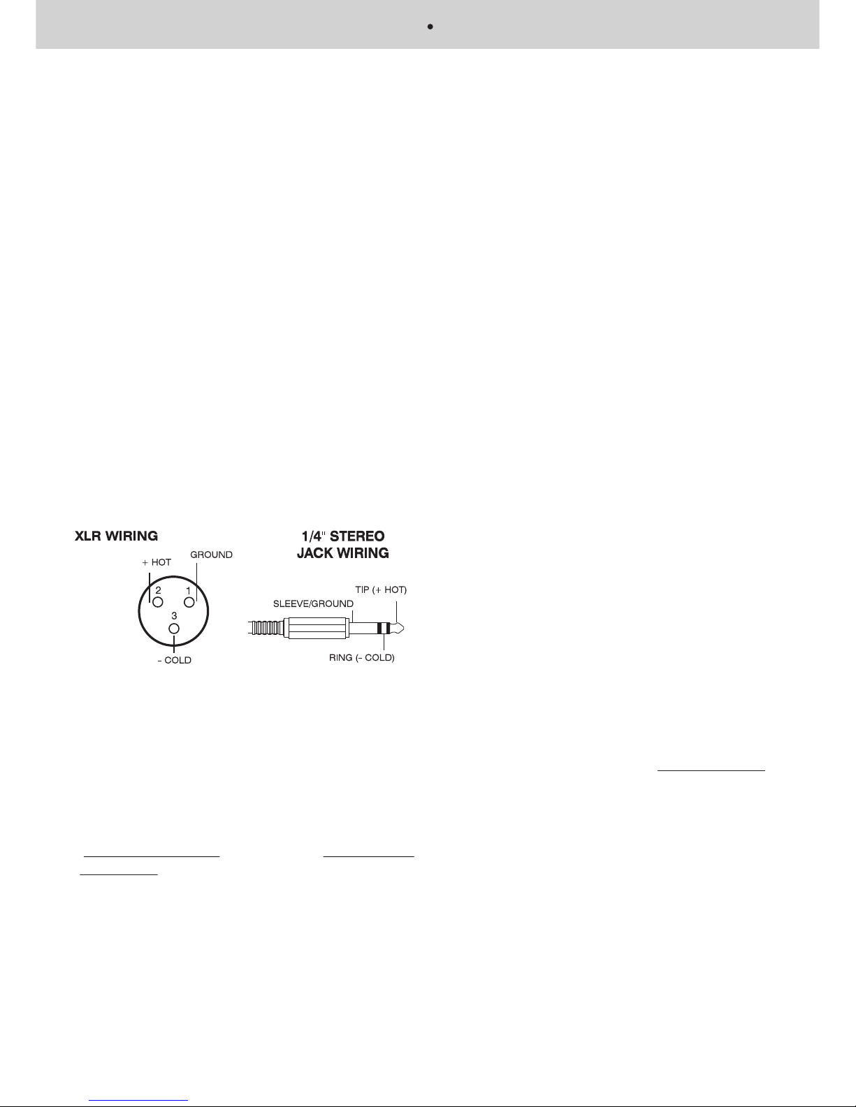
Each input channel is electronically balanced with
female XLR connectors.
In accordance with IEC and AES/ANSI standards the
wiring mode is Pin 1 Earth (signal ground), Pin 2 ,,
(positive) and Pin 3 Cold (negative, return). The1/4
Jack socket is also wired in parallel with the XLR. The
Tip is Hot, the ring is Cold and the Sleeve is Ground.
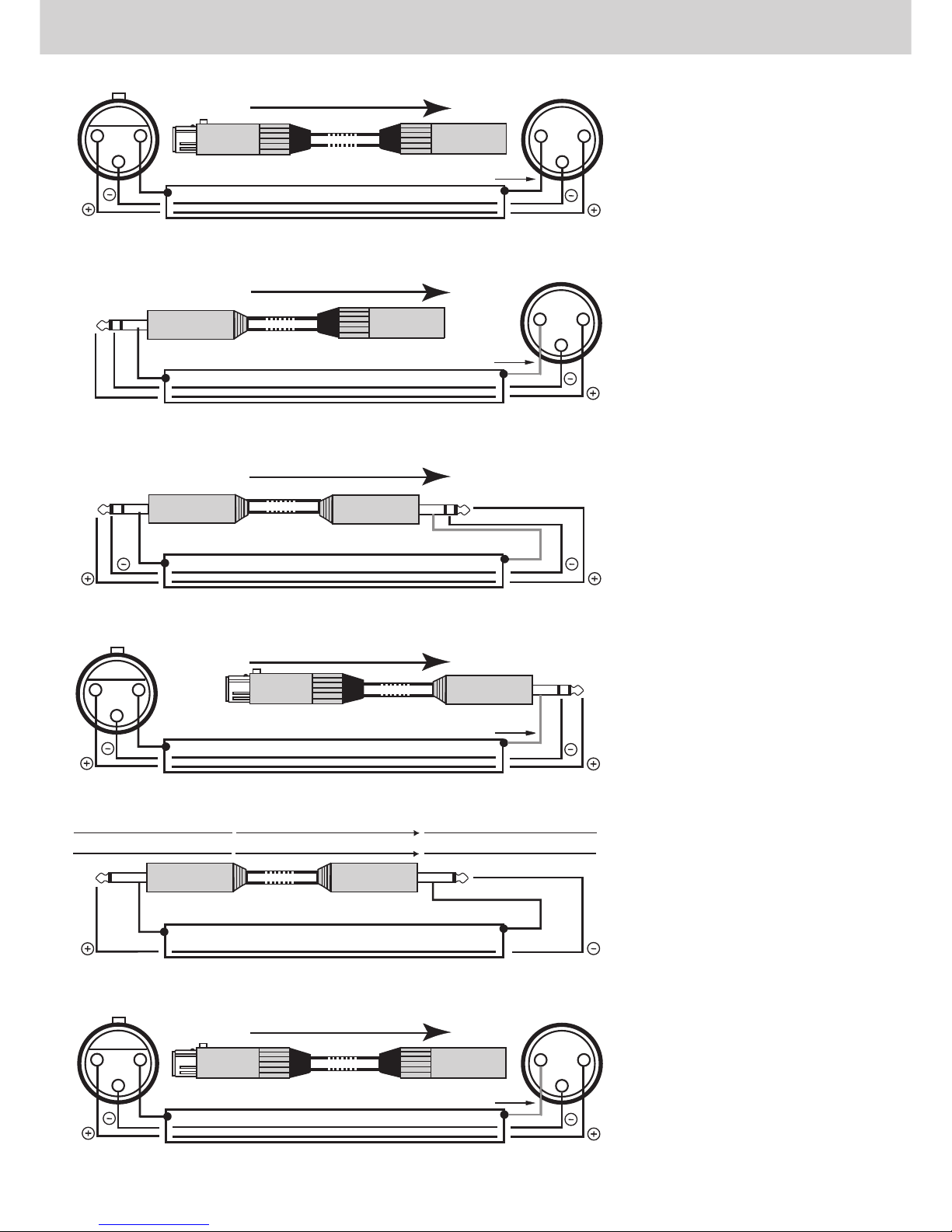
Balanced Operation: Use only when driving from a
true balanced source and driving to a true balanced
destination. Either transformer balanced or with active
drive. Connect the input between pins 2 and 3 with pin
2 positive. Do not connect pin 1. Attached the shield to
connector case (chassis ground). Connect the output
between pins 2 and 3 with pin 2 positive. Do not
connect pin 1. Do not connect the shield at this end to
anything.
Unbalanced Operation: Connect the input between
pins 2 and 1 with pin 2 positive and pin 1 earth (signal
ground). Short pin 3 to pin 1. Attach the shield to
connector case (chassis ground). Connect the output
between pins 2 and 1 with pin 2 positive. Leave pin 3
open - Do not short it to pin 1. Do not connect the
shield at this end to anything.
Operation
The WPG-202 Series of Electronic crossovers can be
used as a 2 way stereo crossover or a mono 3 way
crossover.
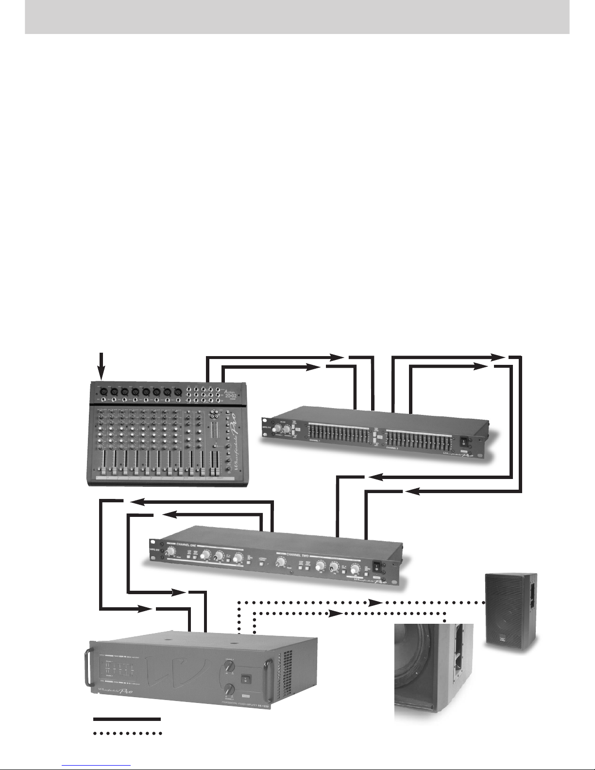
The unit comes in the signal chain before the power
amplifier and after the source (mixer, disco equipment
etc.) and other units such as graphic equalisers or
other equaliser units.
Using the WPG-202 Series of Electronic as a 2 way
stereo crossover
In the stereo mode the switch (12) in the picture would
,
,
be in the out position. The stereo signals should be
inserted at the rear of the unit into channel one and
channel two. The outputs (high and low) would go to
the power amplifier. There are clear legends on the rear
panel showing these input and outputs for the two
operating modes (mono and stereo). To operate set the
input level on channel 1 (left) so that the signal peak
indicator is not flashing constantly (the LED may flash
occasionally but this does not necessarily mean an
overload is occurring). Set the crossover frequency
low/(mid)high control (8) and adjust the low level output
(7) and high level output (10) to the desired levels (see
,
,
below Selecting the right crossover frequencies ).
Follow the same procedure for channel two
remembering that the controls of channel one are the
same as channel two when in Stereo mode. For this
,
,
mode the x1/x10 switch (9) may be need to be in to
enable a higher crossover point to be used
,
(see
,).
Using the WPG-202 Series of Electronic as a 3 way
mono crossover
In the stereo mode the switch (12) in the picture should
,
,
be in the in position. The mono signal should be
inserted at the rear of the unit into channel one only.
The 3 outputs (high, mid and low) should go to the
power amplifier(s). There are clear legends on the rear
showing these input and outputs for the two operating
modes (mono and stereo). To operate set the input
level on channel 1 (left) so that the signal peak
indicator is not flashing constantly (the LED may flash
occasionally but this does not necessarily mean an
overload is occurring). Set the crossover frequency for
low/mid control (8) and adjust the low level output (7)
and mid level output (10) to the desired output levels
,
(see below Selecting the right crossover
,
frequencies ). Select via control no.15 the crossover
point between mid and high and adjust control no.14 for
the high output level.
For this the mono mode switch (16) may be need to be
,
,
in to enable a higher crossover point (see below
WPG SERIES PROFESSIONAL E

,
,
Selecting the right crossover frequencies ).
Selecting the right Crossover Configuration
Whether you choose stereo 2 way or mono 3 way is
usually dependent on your system. Whether you run
true stereo or not is important. A typical 2 way stereo
system would consist on each side a bass bin and a
mid/high loudspeaker with an internal passive
crossover. The crossover would control the frequency
and output level to the bass loudspeaker and the
mid/high loudspeaker. For a simple low/high stereo
system one WPG-202 in stereo mode is ideal and is
the easiest to set up, as you only require one stereo
power amp. A three way system in stereo would require
2 WPG-202 units, each in mono mode, and effectively
3 stereo power amps (one for each band, low, mid and
high). This set up of discrete crossover channels for
each stack of speakers offers increased flexibility and
control for consistent, optimum sound quality. If you ran
a 3 way system mono with one WPG-202 you would
only require 3 channels of power i.e two stereo power
amplifiers with one channel spare for monitors or in
reserve.
Selecting the right Crossover Frequencies
Most speaker/cabinet manufacturers supply low and/or
high frequency cut-off points for each driver. These cut-
off (crossover points) frequencies are badec on the
loudspeaker/drivers performance at and beyond this
point, with a safety margin built in to accommodate
gentler filter roll-offs. Be careful to operate speaker
components within their recommended limits. This will
allow a safety margin so that the crossover points can
be adjusted without damaging the system. Please
remember that the power requirements for high
frequency (Compression drivers/horns) units are far
lower than for low/mid because the sound from a horn
will be far more efficient. This requires careful setting of
the mid/high controls in two way stereo and the high
control in mono mode to minimise the risk of damage to
the speaker units.
TYPICAL WIRING DIAGRAM FOR 2 WAY STEREO OPERATION OF THE WPG - 202 SERIES CROSSOVER
SIGNAL INPUT
MIC, CD etc. TO MIXER
MIXER
OUTPUT
INPUT TO OPTIONAL
SIGNAL PROCESSOR
i.e GRAPHIC EQUALISER
OUTPUTS TO
CROSSOVER
INPUTS TO CROSSOVER
SEPARATE
HIGH/MID
AND LOW
OUTPUTS TO
AMPLIFIER(S)
FROM
CROSSOVER
INPUTS TO AMPLIFIER(S) SEPARATE
LOW
SPEAKER
OUTPUT TO
LOW
FREQUENCY
SPEAKER
FROM
AMPLIFIER
SEPARATE
HIGH/MID
SPEAKER
OUTPUT TO
HIGH/MID
SPEAKER
FROM
AMPLIFIER
= SIGNAL (SHIELDED) CABLE
= LOUDSPEAKER (NON-SHIELDED) CABLE
LECTRONIC CROSSOVER MANUAL

TECHNICAL SPECIFICATION
FREQUENCY RESPONSE: 20Hz - 20kHz +3dB
THD: <0.03%
HUM AND NOISE: -94dB
LEVEL CONTROL RANGE: 0~6dB
INPUT IMPEDANCE: 10K ohm (BALANCED)
OUTPUT IMPEDANCE: <600 ohm (BALANCED)
MAX OUTPUT LEVEL: 22dBm (BALANCED)
MAX: INPUT LEVEL: 22dBm (BALANCED)
FREQUENCY RANGE: 50Hz - 10kHz
HIGH CUT FILTER: 15kHz 12dB/OCTAVE
LOW CUT FILTER: 40Hz 12dB/OCTAVE
CD HORN EQUALISATION: 3kHz
POWER CONSUMPTION: 12 VA
POWER: 95V ~130 VOLTS AC, 50 - 60Hz
190V ~250 VOLTS AC, 50 - 60Hz
DIMENSIONS: (HEIGHT . WIDTH . DEPTH) 483 x 160 x 44 mm / 19 x 6.3 x 1.7 inches
WEIGHT: 2.7Kg (6lbs)
-
POWER SUPPLY FOR WPG SERIES ELECTRONIC CROSSOVER.
UK DISRIBUTED UNITS COME WITH FITTED MAINS PLUG, 250V
13 AMP, BS1363/A I.S.40/A
WPG SERIES PROFESSIONAL E

2 1
3
1 2
3
BALANCED INPUT WIRING TO WHARFEDALE PRO UNIT WITH XLR CONNECTORS
BALANCED OUTPUT
SIGNAL DIRECTION
INPUT to Wharfedale Pro unit
Ground (earth)
CABLE
Only connect ground if hum occurs
,,
BALANCED INPUT WIRING TO WHARFEDALE PRO UNIT WITH 1/4 JACK to XLR CONNECTORS
SIGNAL DIRECTION
BALANCED OUTPUT
INPUT to Wharfedale Pro unit
12
3
Ground (earth) CABLE
Only connect ground if hum occurs
SLEEVE
RING
TIP
RING
21
3
12
3
BALANCED OUTPUT WIRING FROM WHARFEDALE PRO UNIT WITH XLR CONNECTORS TO BALANCED UNIT
OUTPUT from Wharfedale Pro unit
SIGNAL DIRECTION
BALANCED INPUT
Ground (earth)
CABLE
Only connect ground if hum occurs
TIP
SLEEVE
Ground (earth) CABLE
TIP
SLEEVE
INPUT to Wharfedale Pro unitSIGNAL DIRECTIONOUTPUT
INPUTSIGNAL DIRECTIONOUTPUT Wharfedale Pro unit
,,
UNBALANCED INPUT AND OUTPUT WIRING WITH MONO 1/4 JACK CONNECTIONS
2 1
3
Ground (earth)
CABLE
Only connect ground if hum occurs
RING
SIGNAL DIRECTION INPUT to
Wharfedale Pro unit
TIP
SLEEVE
,,
BALANCED INPUT WIRING TO WHARFEDALE PRO UNIT WITH XLR CONNECTORS to STEREO 1/4 JACK
BALANCED OUTPUT
TIP
SLEEVE
Ground (earth) CABLE
Only connect ground if hum occurs
SLEEVE TIP
RING
SIGNAL DIRECTION
INPUT to Wharfedale Pro unit
,,
BALANCED INPUT WIRING TO WHARFEDALE PRO UNIT WITH STEREO 1/4 JACK to XLR CONNECTORS
BALANCED OUTPUT
A great deal of mistakes in sound
installations can be down to wrongly
wired audio connections. It is
important that the connections are
correct to suit your system.
Unbalanced System
An unbalanced audio system is
typically a single conductor shielded
with the centre conductor relaying the
signal and the shield at ground.
Balanced System
Using a balanced audio system is
where a two conductor shielded cable
has each of the two centre conductors
carrying the signal but of opposite
phase. This gives each conductor an
equal but inverted potential difference
from that of the ground.
It is recommend that you use balanced
audio connections if the unit before
your crossover has a balanced output.
This will eliminate interference
such as mains hum. For the best results
common grounding should be avoided.
This means not connecting the ground
on both the crossover input and output
connectors. Wharfedale Pro advise
that you connect the ground (shield) of
the input connecting cable to the
ground of the signal source while
making sure the ground (shield) is not
connected to the crossover input
connector. The output cable connector
from the crossover when connecting to
an amplifier should have the ground
(shield) connected. The input
connector ground (shield) to the
amplifier should not be connected.
This is the process by which the
ground (shield) is connected (tied) at
the source unit but is not connected to
the destination unit. If hum develops in
some instances the ground (shield)
can be connected on the input. Some
manufacturers have units that
recommend that the input connector
ground (shield) is tied and the output
disconnected. In this instance you may
need to connect the input connector
ground (shield) going to the input of
the Wharfedale Pro unit.
If an unbalanced system is used with
XLR connections please connect pin 3
to pin 1 (ground) of the connector. This
will mean that pin 2 transports the
positive (+ / hot) signal. If pin 1 and 3
are not connected this results in the
,
,
negative (- / cold) input being open .
This will give an audible degradation of
the signal to noise ratio. This would
relate to both the input and output
connectors and involve the cable
ground (shield) connected at both.
Please note that some manufacturers
run their units with pin 2 (- / cold) and
pin 3 (+ / hot). This should be looked
out for and then the wiring could be
modified with labelled cables so that
connections of + / hot go to their
corresponding + / hot etc. Some
manufacturers run their units with
balanced inputs and unbalanced
outputs, therefore care should be
taken with the connections when
inserted into the system.
LECTRONIC CROSSOVER MANUAL

Thank you for buying a Wharfedale WPG Series Pro Graphic Equalizer Unit.
These units can be used with other Wharfedale Pro Units of which details can be obtained from your dealer.
EVP Series of High Performance Loudspeakers
WPG-202 Two channel Electronic Crossover SE Series of Power Amplifiers
Lix Series of High Performance Loudspeakers
Action Series Mixers
The information in this manual is subject to shange without notice.
c
All rights reserved 1998 Wharfedale Pro, IAG group
Wharfedale International Limited
Sovereign Court Ermine Business Park
Huntingdon, Cambs PE29 6XU, England.
WHARFEDALE website: www.wharfedale.co.uk
911.344
This manual suits for next models
1
Table of contents
Other Wharfedale Pro Crossover manuals