Whirlpool WAHU User manual

AIR HANDLER INSTALLATION INSTRUCTIONS
AIR HANDLER SAFETY
Table of Contents
AIR HANDLER SAFETY .................................................................1
INSTALLATION REQUIREMENTS................................................2
Tools and Parts ............................................................................2
Outdoor System Requirements ...................................................2
Location Requirements................................................................2
Installation Configurations ...........................................................3
Drain Pan Connections ................................................................4
Electrical Requirements—Models Without
Factory-Installed Electric Heat.....................................................5
Electrical Requirements—Models With
Factory-Installed Electric Heat.....................................................5
Ductwork Requirements ..............................................................6
INSTALLATION INSTRUCTIONS..................................................6
Inspect Shipment .........................................................................6
Install Condensate Drain ..............................................................7
Install Ductwork............................................................................7
Verify Orifice Size .........................................................................8
Connect Refrigerant Lines ...........................................................8
Make Electrical Connections—Models Without
Factory-Installed Electric Heat.....................................................8
Make Electrical Connections—Models With
Factory-Installed Electric Heat.....................................................9
Complete Installation..................................................................12
SEQUENCE OF OPERATION ......................................................14
AIR HANDLER MAINTENANCE ..................................................14
ASSISTANCE OR SERVICE.........................................................14
Accessories ................................................................................14
WARRANTY ..................................................................................15
Whirlpool®Models WAHU, WAHM
065937400
You can be killed or seriously injured if you don't immediately
You can be killed or seriously injured if you don't follow
All safety messages will tell you what the potential hazard is, tell you how to reduce the chance of injury, and tell you what can
happen if the instructions are not followed.
Your safety and the safety of others are very important.
We have provided many important safety messages in this manual and on your appliance. Always read and obey all safety
messages.
This is the safety alert symbol.
This symbol alerts you to potential hazards that can kill or hurt you and others.
All safety messages will follow the safety alert symbol and either the word “DANGER” or “WARNING.”
These words mean:
follow instructions.
instructions.
DANGER
WARNING

2
INSTALLATION REQUIREMENTS
These instructions are intended as a general guide only and do
not supersede any national or local codes in any way.
Compliance with all local, state, or national codes pertaining to
this type of equipment should be determined prior to installation.
Read this entire instruction manual, as well as the instructions
supplied in separate equipment, before starting the installation.
All models are designed for indoor installation only.
The installation of the air handler, field wiring, warm air ducts, etc.
must conform to the requirements of the National Electrical
Code, ANSI/NFPA No. 70 (latest edition) in the United States, and
any state laws, and local ordinances (including plumbing or
wastewater codes). Local authorities having jurisdiction should
be consulted before installation is made. Such applicable
regulations or requirements take precedence over the general
instructions in this manual.
Install the conditioned air plenum, ducts and air filters (not
provided) in accordance with NFPA 90B Standard for the
Installation of Warm Air Heating and Air-Conditioning Systems
(latest edition).
The air handler is provided with flanges for the connection of the
plenum and ducts.
Air filters must be listed as Class 2 furnace air filters.
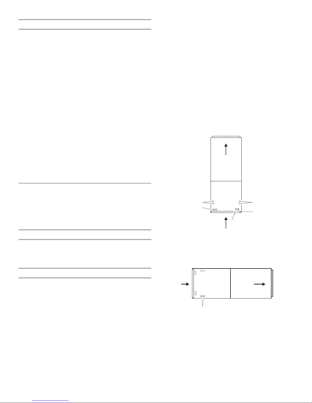
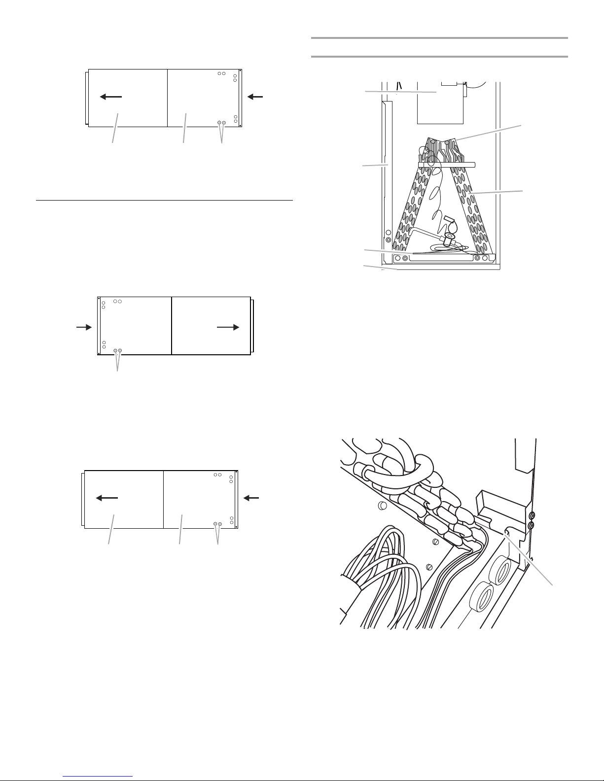
The air handler is shipped from the factory completely
assembled. Some models are configured for upflow air discharge
only, and some models are configured for upflow or horizontal
left-hand air discharge.
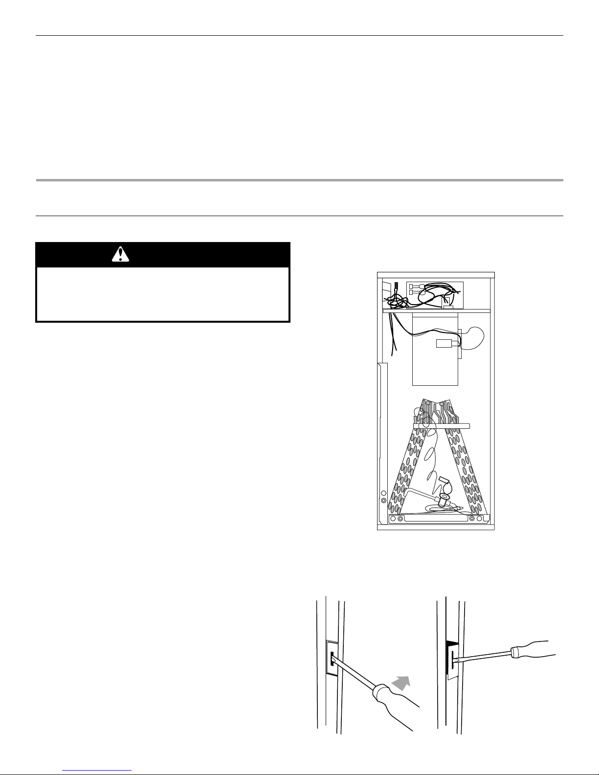
Do not remove the cabinet knockouts until it has been
determined which knockouts will need to be removed for the
installation.
Select the final installation position which best suits the site
conditions. Consider required clearances, space, routing
requirements for refrigerant line, condensate disposal, filters,
ductwork, wiring, and accessibility for service. Refer to the air
handler rating plate on the air handler for specific information.
Tools and Parts
Gather the required tools and parts before starting installation.
Read and follow the instructions provided with any tools listed
here.
Tools Needed
Parts Needed
Check local codes, check existing electrical supply, and read
“Ductwork Requirements,” and “Electrical Requirements,” before
purchasing parts.
Outdoor System Requirements
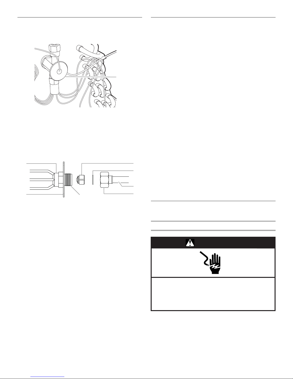
The air handler is designed to match, and must be used with,
outdoor units as rated. The indoor sections are manufactured
with an interchangeable refrigerant metering orifice to provide
optimum refrigerant control and system performance with a
variety of different capacities of outdoor units.
In some cases, the rating of the outdoor unit may require that the
air handler coil assembly orifice be changed to obtain rated
performance.
Location Requirements
NOTE: When used on cooling applications, excessive sweating
may occur when the air handler is installed in a very humid
space.
■If installed in an unconditioned space, sealant should be
applied around the electrical wires, refrigerant tubing, and
condensate lines where they enter the cabinet.
■Electrical wires should be sealed on the inside where they exit
the conduit opening. Sealant is required to prevent air
leakage into and condensate from forming inside the air
handler, control box, and on electrical controls.
■The air handler must be installed in such a way as to allow
free access to the coil/filter compartment and blower/control
compartment.
■When installed in the horizontal position, the air handler must
have a ³⁄₄" drop toward the drain outlet of the drain pan to
ensure proper condensate drainage.
■¹⁄₄" nut driver
■Level
■Screwdriver
■Adjustable wrench
■Tape measure
■Hammer
■Sealant
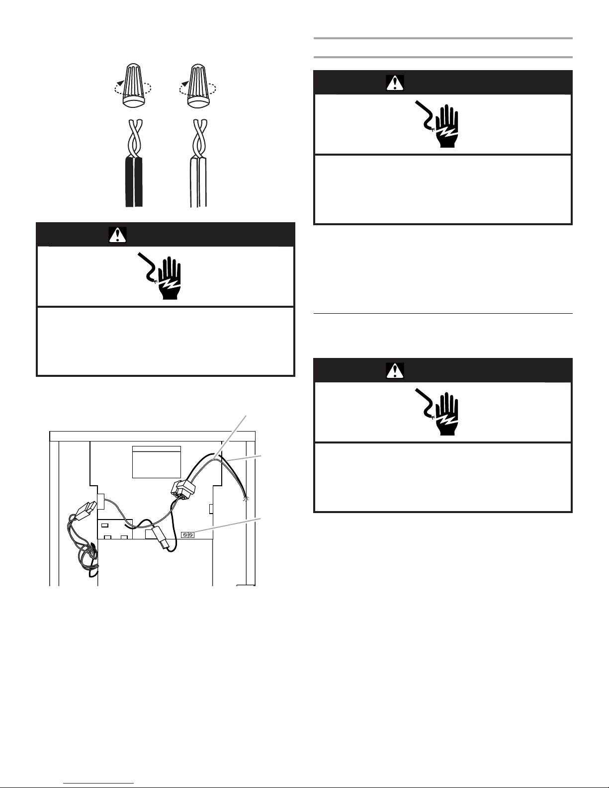
■UL listed wire nuts
■Replacement orifice (if needed). See “Verify Orifice Size.”
The correct orifice size may be contained in the
replacement orifice package located inside the control box
of the outdoor unit. If this package does not contain the
correct orifice for your air handler, you must purchase the
correct orifice size.
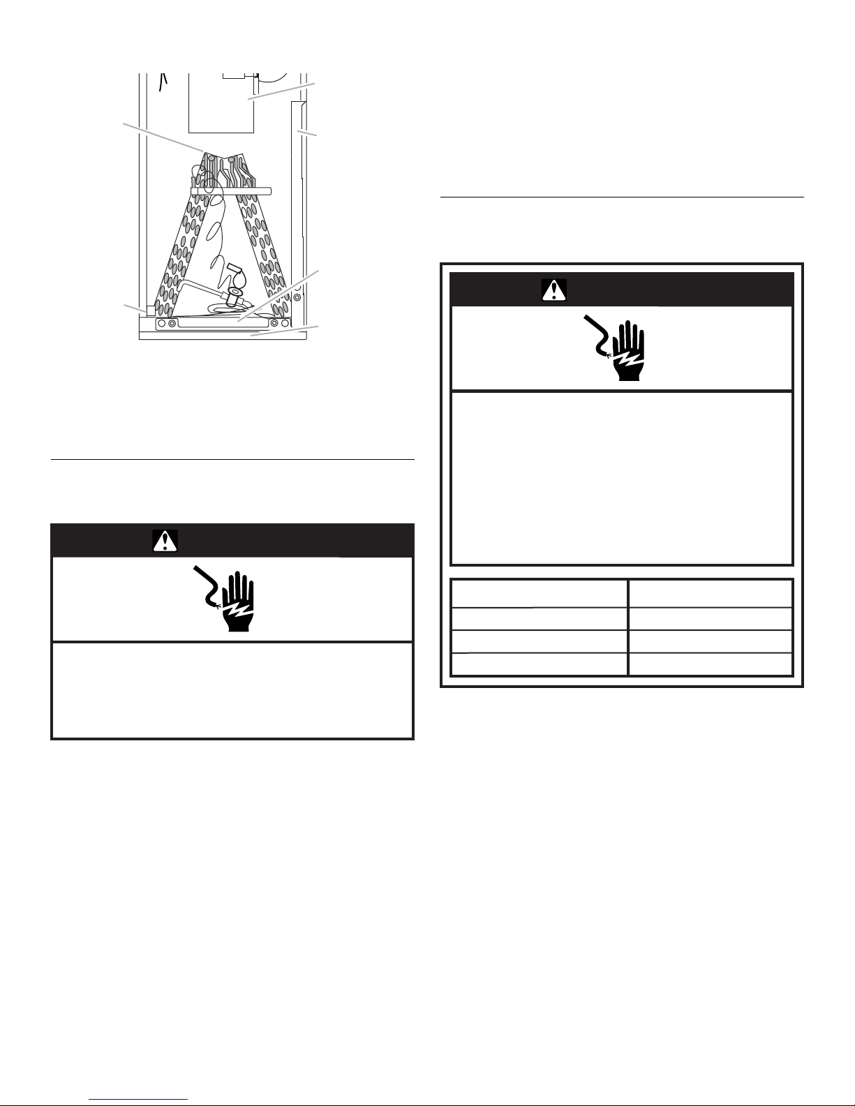
Explosion Hazard
Keep flammable materials and vapors, such as
gasoline, away from air handler.
Place air handler so that heating elements are at least
18 inches (46 cm) above the floor for a garage
installation.
Failure to follow these instructions can result in death,
explosion, or fire.

3
Installation Clearances
Non-Ducted Return Closet Installation
The air handler can be installed in a closet with a false bottom to
form a return air plenum or be installed with a return air plenum
under the air handler.
Louvers or return air grilles are field supplied. Local codes may
limit application of systems without a ducted return to single-
story buildings.
■For a unit installed in a closet with a louvered return opening,
the minimum open area for the louvers will be as shown
below.
■If the free area is not known, assume a 25% free area for
wood or a 75% free area for metal louvers or grilles.
■Using the louver dimensions and the 25% or 75%
assumption, determine if the louver open area meets the
minimum open area listed above.
■If the return air plenum is used, the return air grille should be
immediately in front of the opening in the plenum to allow for
the free flow of return air.
■When not installed in front of the opening, there must be
adequate clearance around the air handler to allow for the
free flow of return air.
Installation Configurations
For ease in installation, it is best to make any necessary coil
configuration changes before setting air handler in place. See
“Installation Configuration Options.”
■Upflow air discharge only contains 1 drain pan.
■Upflow or horizontal airflow contains 2 drain pans.
Vertical Installations
Upflow
The air handler must be supported on the bottom only and set on
a field-supplied supporting frame with an air return opening.
Securely attach the air handler to the supporting frame.
Horizontal Installations
Horizontal installations can be left-hand or right-hand air supply.
Adequate support must be provided to ensure cabinet integrity.
Ensure that there is adequate room to remove, service and
access panels if installing in the horizontal position. For correct
horizontal coil installation, see “Installation Configuration
Options” later in this section.
IMPORTANT:
■This coil is provided with a secondary drain that should be
trapped and piped to a location that will give the occupant a
visual warning that the primary drain is clogged. See “Install
Condensate Drain.”
■When an evaporator coil is installed in an attic or above a
finished ceiling, an auxiliary drain pan should be provided
under the air handler as specified by most local building
codes.
Conversion from Vertical to Horizontal
An upflow only air handler may be converted to horizontal air
discharge by installing a horizontal drain pan kit. See
“Accessories.”
An upflow/horizontal air handler may be converted from
horizontal left-hand discharge to horizontal right-hand discharge
without additional parts.
Suspended Cabinet Installation
NOTE: Air handlers cannot be installed horizontally lying on or
suspended from either the front or back of the air handler. It must
be positioned with one side parallel to the floor when in the
horizontal position.
The suspending means must be field fabricated, and should
consist of 2 “cradles” made by attaching 2 rods to a length of
angle iron or suitable gauge steel.
Installation Configuration Options
18" and 24" models 320 sq. in.
30" and 36" models 360 sq. in.
42", 48" and 60" models 450 sq. in.
A. Horizontal drain connections
(left or right hand) B. Upflow drain connections
C. Bottom/filter frame
A. Drain connections
Shading indicates proper line connections
As shipped from the factory
(return in bottom)
C
A
A
B
Upflow
B
A
Horizontal Right
Left to Right Airflow: Requires drain pan
location change.
Drains

4
.
Drain Pan Connections
Horizontal Installations can be either “Right” or “Left.”
For Horizontal Right Installations, a drain pan location change is
required. Use drain connections marked “A” below.
For Horizontal Left Installations, use drain connections marked
“A” below.
Conversion to Horizontal Right
Before Conversion
1. Remove screws from the blower access cover and lift off of
the unit. Set aside.
2. Remove screws from the coil access cover and lift off of the
unit. Set aside.
3. Remove screws from the coil support bracket and lift off of
the unit. Set aside.
4. Remove the coil/drain pan assembly by lifting and sliding out.
The assembly consists of the coil, the bottom drain pan and
the side drain pan.
5. Remove the side drain pan from the coil/drain pan assembly
and install on the opposite side.
6. Reinstall the coil/drain pan assembly in the same orientation
as before by lifting and sliding into the air handler.
7. Install the coil support bracket on the opposite side of the air
handler.
A. Drain connections
B. Coil access cover
C. Blower access cover
A. Drain connections
B. Coil access cover
C. Blower access cover
Factory ready (on some models)
Drains
A
Horizontal Left
BC
A
Horizontal Right
Left to Right Airflow: Requires drain pan
location change.
Drains
Factory ready (on some models)
Drains
A
Horizontal Left
BC
A. Filter access door
B. Bottom drain pan
C. Side drain pan
D. Blower
E. Top cap
F. Coil/Drain pan assembly
(consists of coil, bottom
drain pan and side drain pan)
A. Coil support bracket
C
B
A
E
D
F
A

5
After Conversion
8. Determine knockouts required for drain line connections and
remove.
9. Replace the blower and coil access covers.
Electrical Requirements—Models Without
Factory-Installed Electric Heat
NOTE: Use copper conductors only.
■All field wiring must be done in accordance with National
Electrical Code, applicable requirements of UL and local
codes, where applicable.
■Electrical wiring, disconnect means and over-current
protection are to be supplied by the installer. Refer to the air
handler rating plate for maximum over-current protection,
minimum circuit ampacity, as well as operating voltage.
■The power supply must be sized and protected according to
the specifications supplied on the product.
■This air handler is factory-configured for 120-volt or 240-volt,
single phase, 60 cycles. For 208-volt applications, see
“208-Volt Conversion” in the “Make Electrical Connections—
Models Without Factory-Installed Electric Heat” section.
■For optional electric heater applications, see “Accessories.”
Refer to the instructions provided with the accessory for
proper installation.
Electrical Requirements—Models With
Factory-Installed Electric Heat
NOTE: Use copper conductors only.
■All field wiring must be done in accordance with National
Electrical Code, applicable requirements of UL and local
codes, where applicable.
■Electrical wiring, disconnect means and over-current
protection are to be supplied by the installer. Refer to the air
handler rating plate for maximum over-current protection,
minimum circuit ampacity, as well as operating voltage.
■The power supply must be sized and protected according to
the specifications supplied on the product.
■This air handler is factory-configured for 240-volt, single
phase, 60 cycles. For 208-volt applications, see “208-Volt
Conversion” in the “Make Electrical Connections—Models
Without Factory-Installed Electric Heat” section.
A. Coil support bracket
B. Filter access door
C. Bottom drain pan
D. Side drain pan
E. Blower
F. To p ca p
A
B
C
D
E
F
WARNING
Electrical Shock Hazard
Electrically ground air handler.
Connect ground wire to ground terminal marked “GND”.
Failure to do so can result in death or electrical shock.
WARNING
Electrical Shock Hazard
Electrically ground electric heater.
Connect ground wire to ground terminal
marked “GND.”
Use copper wire rated for supply connection.
Correct wire gauge is shown in the chart below.
Failure to follow these instructions can result in
death or electrical shock.
Rating Plate Ampacity
21 - 30
31 - 40
41 - 60
AWG
10
8
6

6
Ductwork Requirements
■Install the conditioned air plenum, ducts and air filters (not
provided) in accordance with NFPA 90B Standard for the
Installation of Warm Air Heating and Air-Conditioning
Systems (latest edition).
■The air handler is provided with flanges for the connection of
the plenum and ducts.
■The air handler is equipped with flanges that can form a filter
rack for the installation of the air filter, or the filter may be
installed as part of the return air duct system.
■Air filters must be listed as Class 2 furnace air filters.
■Supply and return ductwork must be adequately sized to
meet the system’s air requirements and static pressure
capabilities. Ductwork should be insulated with a minimum of
1" thick insulation with a vapor barrier in conditioned areas or
2" minimum in unconditioned areas.
■Supply plenum should be the same size as the flanged
opening provided around the blower outlet and should
extend ideally at least 3 ft from the air handler before turning
or branching off plenum into duct runs.The plenum forms an
extension of the blower housing and minimizes air expansion
losses from the blower.
INSTALLATION INSTRUCTIONS
Inspect Shipment
These air handlers are completely factory assembled, and all
components are performance tested. Each unit consists of a
blower assembly, refrigerant coil, and controls, in an insulated
galvanized steel factory finished enclosure. Knockouts are
provided for electrical wiring entrance.
1. Check the unit rating plate to confirm specifications are as
ordered.
2. Upon receipt of equipment, thoroughly inspect it for possible
shipping damage. Closely examine the unit inside the carton
if the carton is damaged.
If damage is found, it should be noted on the carrier’s freight bill.
Damage claims should be filed with the carrier immediately.
Claims of shortages should be filed with the seller within 5 days.
NOTE: If any damages are discovered and reported to the carrier,
do not install the unit because your claim may be denied.
If a filter is to be installed at the air handler, a filter rack must be
formed using factory-supplied flanges.
1. Lay air handler on its back.
2. Pry filter rack tabs out.
Excessive Weight Hazard
Use two or more people to move and install air handler.
WARNING
Failure to do so can result in back or other injury.

7
3. Place air handler in vertical position.
Filter Size Chart
Install Condensate Drain
The air handler is provided with ³⁄₄" NPT condensate drain
connections.
A field-fabricated secondary drain pan, with a drainpipe to the
outside of the building, is required in all installations over a
finished living space or in any area that may be damaged by
overflow from the main drain pan. In some localities, local codes
may require an secondary drain pan for any horizontal
installation.
When installed in the horizontal position, the air handler must
have a ³⁄₄" drop toward the drain outlet of the drain pan to ensure
proper condensate drainage.
1. Remove the appropriate drain knockouts. See “Drain Pan
Connections” section. You may need to remove the indoor
coil assembly from the cabinet.
2. Remove any web from inside any threaded drain pan hole to
which a drain line is to be connected. Gently remove the web
so as not to damage the coil.
3. Connect primary drain line connection to the primary drain
pan connection. The primary drain connection is flush with
the bottom of the inside of the pan. Secondary connection is
raised above the bottom of the inside of the pan.
NOTE: When making drain fitting connections to the drain
pan, hand tighten. Using a sealant is recommended.
Overtightening the fittings can split connections on the drain
pan.
4. Secondary drain connections, if used, should be connected
to a separate drainage system. Run the secondary drain line
to a place where the occupant would notice if water started
coming from the secondary drain.
5. Install a 3" trap in both the primary and secondary drain lines
as close to the unit as practical. Make sure the top of the trap
is below the connection to the drain pan to allow complete
drainage of the pan.
NOTE: Horizontal runs must also have an anti-siphon air vent
(standpipe) installed ahead of the horizontal run. See “Typical
Condensate Drain Connection” in this section. An extremely
long horizontal run may require an oversized drain line to
eliminate air trapping.
Typical Condensate Drain Connection
(secondary drain not shown)
NOTE: Do not operate air handler without a drain trap. The
condensate drain is on the negative pressure side of the blower;
therefore, air being pulled through the condensate line will
prevent positive drainage without a proper trap.
6. Route the drain line to the outside or to an appropriate drain.
Drain lines must be installed so they do not block service
access to the front of the air handler. A 24" clearance is
required for filter, coil, or blower removal and service access.
NOTE: Check local codes before connecting the drain line to
an existing drainage system.
7. Insulate the drain lines where sweating could cause water
damage.
Test condensate drain pan and drain line after installation:
1. Pour several quarts of water into drain pan, enough to fill
drain trap and line.
2. Check to make sure the drain pan is draining completely, no
leaks are found in drain line fittings, and water is draining
from the end of the primary drain line.
3. Correct any leaks found.
Install Ductwork
IMPORTANT:
■Install ductwork in accordance with NFPA 90B and any local
codes.
■Connect supply air duct to the flange on top of the air
handler. If an isolation connector is used, it must be
nonflammable.
■A return air duct system is recommended. If the unit is
installed in a confined space or closet, a return connection
must be run, full size, to a location outside the closet.
Model Filter Size
18 / 24 16" x 20"
30 / 36 18" x 20"
42 / 48 / 60 18" x 25"
A. Air handler
B. Drain connection
C. Drain line
D. Anti-siphon air vent
E. Drain trap
F. Auxiliary drain pan
3.00" Min.
1.00" Min.
12.00"Max.
AB
D
E
C
F

8
Verify Orifice Size
NOTE: Some models are equipped with thermo expansion valve
and do not require any orifice change.
IMPORTANT: The proper orifice size is dependent on indoor coil/
outdoor unit combination and application.
1. Consult the outdoor unit literature to determine whether the
indoor unit has the correct orifice installed.
2. If a change of the orifice is required, loosen the brass hex nut
and separate the orifice extension stub from the brass hex
fitting.
3. Remove the orifice with an orifice extractor tool.
4. Insert the proper orifice into the fitting, seal end first. Make
sure the orifice is free to move in the fitting.
5. Replace the brass hex nut.
NOTE: Overtightening the brass hex nut will crush the gasket
and may result in a system leak or stuck piston.
6. Dispose of all packaging and unused parts.
Connect Refrigerant Lines
Refrigerant lines must be connected by a licensed, EPA certified
refrigerant technician in accordance with established procedures.
IMPORTANT:
■Connecting refrigerant lines must be clean, dehydrated,
refrigerant-grade copper lines. Air handler coils should be
installed only with specified line sizes for approved system
combinations.
■Handle the refrigerant lines gently during the installation
process. Sharp bends or possible kinking in the lines will
cause a restriction.
■Do not remove the caps from the lines or system connection
points until connections are ready to be completed.
1. Route the suction and liquid lines from the fittings on the
indoor coil to the fittings on the outdoor unit. Run the lines in
as direct a path as possible avoiding unnecessary turns and
bends.
2. Make sure that the suction line is insulated over the entire
exposed length and that both suction and liquid lines are not
in direct contact with floors, walls, ductwork, floor joists, or
other piping.
3. Connect the suction and liquid lines to the evaporator coil.
4. To avoid damaging the rubber grommets in the cabinet while
brazing, slide the rubber grommets over the refrigerant lines
until they are away from the heat source.
5. Braze with an alloy of silver or copper and phosphorus with a
melting point above 1,100°F.
NOTE: Do not use soft solder.
6. Reinstall the rubber grommets after brazing is finished.
7. Make sure outdoor condenser/heat pump has been put in
place according to the Installation Instructions and is
connected to the refrigerant lines.
Make Electrical Connections—Models Without
Factory-Installed Electric Heat
240-Volt Installations
1. Disconnect all power supplies.
2. Remove the blower access panel.
3. Route the field supply wires to the air handler electrical
connection box.
A. Thermo expansion valve
A. Distributor fitting
B. Mounting flange
C. Piston orifice
D. Ring seal (supplied)
E. Orifice extension stub
F. 0.812" brass hex nut
G. Brass hex fitting
A
A
B
D
E
C
F
G
WARNING
Electrical Shock Hazard
Disconnect all power supplies before servicing.
Replace all parts and panels before operating.
Failure to do so can result in death or electrical shock.

9
4. Using UL listed wire nuts, connect the field supply wires to
the air handler (black to black and yellow to yellow).
5. Connect ground wire to ground terminal marked “GND.”
6. Replace the blower access panel.
208-Volt Conversion
1. Disconnect all power supplies.
2. Remove the air handler access panel.
3. Move the 2 connected black transformer leads from the
240-volt terminal on the transformer to the 208-volt terminal
on the transformer. See “Wiring Diagram—Electric Heat and
Blower” in the “Make Electrical Connections—Models with
Factory-Installed Electric Heat” section.
Make Electrical Connections—Models With
Factory-Installed Electric Heat
1. Determine the number of circuits needed to supply the heater
with electrical power (1, 2, or 3 circuits). See the air handler
Accessory Kit label for number of circuits and ratings.
2. Disconnect all power supplies.
3. Knock out the correct number of knockouts (1, 2, or 3), and
install UL listed wires and fittings.
A. Connect yellow to yellow
B. Connect black to black
C. Connect ground wire to ground terminal marked “GND”
WARNING
Electrical Shock Hazard
Electrically ground air handler.
Connect ground wire to ground terminal marked “GND”.
Failure to do so can result in death or electrical shock.
GND
A
B
C
WARNING
Electrical Shock Hazard
Disconnect all power supplies before servicing.
Replace all parts and panels before operating.
Failure to do so can result in death or electrical shock.
WARNING
Electrical Shock Hazard
Disconnect all power supplies before servicing.
Replace all parts and panels before operating.
Failure to do so can result in death or electrical shock.

10
4. Connect appropriate size wire to the circuit breaker terminals.
If circuit breakers are not provided, a terminal block is
provided.
5. Connect green ground wire(s) (1, 2, or 3) to ground terminal(s)
(1, 2, or 3) marked “GND.”
Connect to Circuit Breaker
NOTE: There are 2 ground terminals marked “GND” shown here.
There may be 1, 2 or 3 ground terminals depending on the
number of circuit breakers.
Connect to Terminal Block
6. Install conduit opening plugs in any unused openings.
7. If circuit breakers or pull disconnects are used, the front panel
knockouts will need to be removed.
8. Reinstall the air handler blower access panel.
9. Reconnect power.
10. Dispose of/recycle all remaining parts.
WARNING
Electrical Shock Hazard
Electrically ground electric heater.
Connect ground wire to ground terminal
marked “GND.”
Use copper wire rated for supply connection.
Correct wire gauge is shown in the chart below.
Failure to follow these instructions can result in
death or electrical shock.
Rating Plate Ampacity
21 - 30
31 - 40
41 - 60
AWG
10
8
6
GND
Field Supply
Ground Wires
Circuit 1
Circuit 2
L1
L2
L1
L2
208/230 Volt
Field Supply Wires
ON
OFF
60
ON
OFF
60
GND
L1
L2
L1
L2
208/230 Volt
Field Supply Wires
Field Supply
Ground Wires

11
Low Voltage Connections
R
G
BU
Thermostat Air Handler
Condensing
Unit
Cooling Only Application
Heat Only Application
Thermostat Air Handler
Air Handler
Air HandlerThermostat Thermostat
R
R
R
G
G
G
BU
BU
W
W
W
Heat Pump Unit
BK
BK
Cooling Application with Electric Heat
Heat Pump Application with Electric Heat
Condensing
Unit
Connect common wire only if required.
See thermostat installation instructions.

12
Wiring Diagram - Electric Heat and Blower
15 Amp
Supply
Voltage
L1
L2 OR
N
Wiring Diagram: No Heat
Wire Nuts
By Others
14 G
2
14 BK
1
To
Ground Lug
14 Y (240V)
14 W (120V)
6-Pin
Plug
18 R
18 BU
14 R
18 BK
18 G
18 BU
4
BR
6
2
5
3
1
TR
14 BK
240V
18 BU
208V
COM
24V
14 BK L1
14 Y L2
BK
18 R
18 G
R
G
18 W
18 BU C
W1
To
Thermostat
By Others
R
G
W
BU
W2
CAP = Motor Capacitor
GND = Ground Connection
MTR = Blower Motor
BR = Blower Relay
TD = Time Delay (Opt.)
TR = Transformer
SEQ = Sequencer
CB = Circuit Breaker
GND = Ground Lug
LS = Limit Switch
HE = Heater Element
Wiring Diagram - Electric Heat
Control Circuit Wiring To
Be 24 Volt, N.E.C. Class 2
Power (Factory Wired)
Power (Field Wired)
Control (Factory Wired)
Control (Field Wired)
Plug Pin
Location
(Opt.)
Amp 350781-1
6-Pin Cap
4
1
56
23
TB = Terminal Block (Opt.)
Heaters Used
5 KW = HE1
7.5 & 10 KW = HE1 & HE2
15 KW = HE1,HE2 & HE3
20 KW = HE1,HE2,HE3 & HE4
24
C
3
2
65
1
4
W (IF 120V)
GND
BR
BR/W
3
4
R
BK MTR
Cap
1
Y
14 BK (HI)
14 Y (COM)
2
14 R (LO)
Part No. 065866900
Line Voltage
by Others
TD
HH
12 BK
12 BK
56
123 4
To Blower
Ground Lug
14 BK
14 Y
12
18 BU
14 G
4
18 W
5
L2A
L1A
CB1
GND
12 BK
12 BK
3
54
1
SEQ1
14 R
3
Plug
6-Pin
12 Y
12 Y
12 BK
LS2
LS1
HE2
HE1
12 BK
1st Stage
6
OR
220V
+
**
+
**
120V
CB2
SEQ2
18 BU
5
3
4
1
12 Y LS4
HE4
LS3
12 BK
HE3
12 Y
12 BK
GND.
L1B
L2B
2nd Stage
18 BK

13
Complete Installation
NOTE: Refer to outdoor unit installation instructions for system
start-up instructions and refrigerant charging instructions.
Pre-Start Check
■Is unit properly located, level, secure, and serviceable?
■Has an auxiliary pan been provided under the unit with
separate drain for units installed above a finished ceiling or in
any installation where condensate overflow could cause
damage?
■Have all webs been removed from the drain connections that
are being used? Have all drain pan plugs not used been
properly plugged?
■Has the condensate line been properly sized, run, trapped,
pitched, and tested?
■Is the ductwork correctly sized, run, taped, and insulated?
■Have all cabinet openings and wiring been sealed?
■Is the indoor coil orifice size correct?
■Have all unused orifice replacement parts and packaging
been disposed of?
■Is the filter clean, in place, and of adequate size?
■Is the wiring neat, correct, and in accordance with the wiring
diagram?
■Is the unit properly grounded and protected (fused)?
■Is the thermostat correctly wired and in a good location?
■Are all access panels in place and secure?
Check Blower Operation
1. Set thermostat to FAN ON.
2. The indoor blower should come on.
Check Electric Heater (if used)
1. Set thermostat to call for auxiliary heat (approximately 5°F
above ambient temperature). The indoor blower and auxiliary
heat should come on together. Allow a minimum of 3 minutes
for all sequencers to cycle on.
2. Set the thermostat so it does not call for heat. Allow up to
5 minutes for all sequencers to cycle off.
Check Airflow
Cooling blower speed
■For proper cooling operation, the airflow through the indoor
coil should be between 350 and 450 CFM per ton of cooling
capacity (or 350 - 450 CFM per 12,000 Btu/h) based on the
rating of the outdoor unit.
■The cooling blower speed is factory configured to provide
correct airflow for an outdoor unit that matches the maximum
cooling capacity rating of the air handler.
■If the outdoor unit is smaller than the maximum cooling
capacity rating for the air handler, the cooling blower speed
may need to be changed. Refer to Blower Performance
Chart.
IMPORTANT: The cooling blower speed must be set to provide a
minimum of 350 CFM airflow per ton (12,000 Btu/h) of outdoor
cooling capacity.
To change blower speed: Refer to “Wiring Diagram—
Electric Heat and Blower.”
1. Disconnect all power supplies.
2. Remove the air handler access panel.
3. Locate pin number 2 on the blower relay. Two black wires are
connected to this terminal pin. One connects to pin number 5
on the blower relay, one connects to an inline splice
connecting to a red or black wire.
4. Remove the wire going to the 4-pin blower motor connector
from the splice.
5. Connect the blower lead (Red [LO], Black [HI]) onto the splice
from the 4-pin blower motor connector.
NOTE: Unused blower speeds are shipped from the factory
covered with a plastic cap. Remove this cap from the new
blower speed terminal and replace it over the factory-set
blower terminal.
6. Replace all panels.
7. Reconnect power.
Blower Performance Chart
Air
Handler
Model Blower
Speed
CFM @ ESP. - in. W.C.
0.1 0.2 0.3 0.4 0.5
18 High (Black) 952 886 795 679 529
Low (Red) 727 640 598 520 393
24
High (Black) 1,054 979 912 818 686
Low (Red) 1,033 925 854 754 621
30
High (Black) 1,298 1,252 1,202 1,130 1,031
Low (Red) 1,041 1,026 992 936 837
36
High (Black) 1,531 1,466 1,391 1,287 1,181
Low (Red) 1,294 1,262 1,216 1,139 1,049
42
High (Black) 1,670 1,600 1,511 1,393 1,218
Low (Red) 1,535 1,475 1,406 1,264 1,141
48
High (Black) 1,829 1,718 1,620 1,484 1,271
Low (Red) 1,754 1,654 1,553 1,423 1,214
60
High (Black) 2,119 1,964 1,845 1,692 1,494
Low (Red) 2,049 1,934 1,813 1,684 1,468
All factory settings are low-speed.
All data given while air handler is operating with a dry DX coil
and no air filter installed.
WARNING
Electrical Shock Hazard
Disconnect all power supplies before servicing.
Replace all parts and panels before operating.
Failure to do so can result in death or electrical shock.

14
SEQUENCE OF OPERATION
Cooling (cooling only or heat pump)
When the thermostat calls for cooling, the circuit between R and
G is completed, and the blower relay is energized. The Normally
Open contacts close, causing the indoor blower motor to
operate. The circuit between R and Y is also completed; this
circuit closes the contactor in the outdoor unit starting the
compressor and outdoor fan motor. Circuit R and O energizes the
reversing valve, switching it to the cooling position. (The
reversing valve remains energized as long as selector switch is in
the COOL position.)
Heating (electric heat only)
When the thermostat calls for heat, the circuit between R and W
is completed, and the heater sequencer is energized. A time
delay follows before the heating elements and the indoor blower
motor come on. Units with a second heat sequencer can be
connected with the first sequencer to W on the thermostat
subbase or connected to a second stage on the subbase.
Heating (heat pump)
When the thermostat calls for heat, the circuits between R and Y
and R and G are completed. Circuit R-Y energizes the contactor
starting the outdoor fan motor and the compressor. Circuit R and
G energizes the blower relay starting the indoor blower motor.
If the room temperature should continue to fall, the circuit
between R and W 1 is completed by the second stage heat room
thermostat. Circuit R-W 1 energizes a heat sequencer. The
completed circuit will energize supplemental electric heat (if
applicable). Units with a second heater sequencer can be
connected with the first sequencer to W 1 on the thermostat or
connected to a second heating stage W 2 on the thermostat
subbase.
Emergency Heat (heating heat pump)
If selector switch on thermostat is set to the emergency heat
position, the heat pump will be locked out of the heating circuit,
and all heating will be electric heat (if applicable). A jumper
should be placed between W 2 and E on the thermostat subbase
so that the electric heat control will transfer to the first stage heat
on the thermostat. This will allow the indoor blower to cycle on
and off with the electric heat when the fan switch is in the AUTO
position.
AIR HANDLER MAINTENANCE
IMPORTANT: Do not operate system without a filter. A filter is
required to protect the coil, blower, and internal parts from
excessive dirt and dust. See “Installation Configurations” for the
location of the filter in the unit cabinet and the service panel
giving access to unit filter. The filter is placed in the supply air
return duct by the installer.
■Inspect air filters at least once a month and replace or clean
as required. Dirty filters are the most common cause of
inadequate heating or cooling performance.
■Replace disposable filters. Cleanable filters can be cleaned
by soaking in mild detergent and rinsing with cold water.
■Install new/clean filters with the arrows on the side pointing in
the direction of airflow.
■Do not replace a cleanable (high velocity) filter with a
disposable (low velocity) filter unless return air system is
properly sized for it.
■If water should start coming from the secondary drain line, a
problem exists which should be investigated and corrected.
Contact a qualified person.
ASSISTANCE OR SERVICE
If you need further assistance, you can write to the below
address with any questions or concerns:
Whirlpool®Home Cooling and Heating
317 S. North Lake Blvd.
Altomonte Springs, FL 32701
Please include a daytime phone number in your correspondence.
Accessories
Electric Heat Kits
Refer to the accessory kit label on the front panel of the air
handler for electric heat kit accessory options and applications.
Horizontal Drain Pan Kit
Consult with your distributor to obtain the part number for this kit.

15

Keep this book and your sales slip together for future
reference. You must provide proof of purchase or installation
date for in-warranty service.
Write down the following information about your air handler to
better help you obtain assistance or service if you ever need it.
You will need to know the complete model and serial number. You
can find this information on the air handler rating plate.
Dealer name____________________________________________________
Address ________________________________________________________
Phone number__________________________________________________
Model number __________________________________________________
Serial number __________________________________________________
Installation date ________________________________________________
065937400
© 2005. All rights reserved. ®Registered Trademark/TM Trademark of Whirlpool, U.S.A.,
Manufactured under license by Tradewinds Distributing Company, LLC., Coconut Grove, Florida 11/05
Printed in U.S.A.
This manual suits for next models
1
Table of contents
Other Whirlpool Air Handler manuals
Popular Air Handler manuals by other brands

Daikin
Daikin Easdale 25 Installation, operation and maintenance instructions

BLAUBERG
BLAUBERG KOMFORT Roto EC LHP400 S17 user manual

BLAUBERG
BLAUBERG CIVIC EC DB 300 V.2 user manual

Flexit
Flexit UNI 4 user manual

IV Produkt
IV Produkt Envistar Flex Assembly instructions

Blue Summit
Blue Summit LRP16HP installation instructions

Bryant
Bryant 524J 07 Installation, Start-Up and Service Instructions

Goodman
Goodman AEPF SUPPLEMENTAL & OPEATING INSTRUCTIONS

Lennox
Lennox SL280DFNV Series Unit information

Carrier
Carrier 42DW Series Installation instruction

Zehnder Rittling
Zehnder Rittling CALADAIR EDT2 Installation, service and user manual

Flexit
Flexit Spirit K2 quick guide