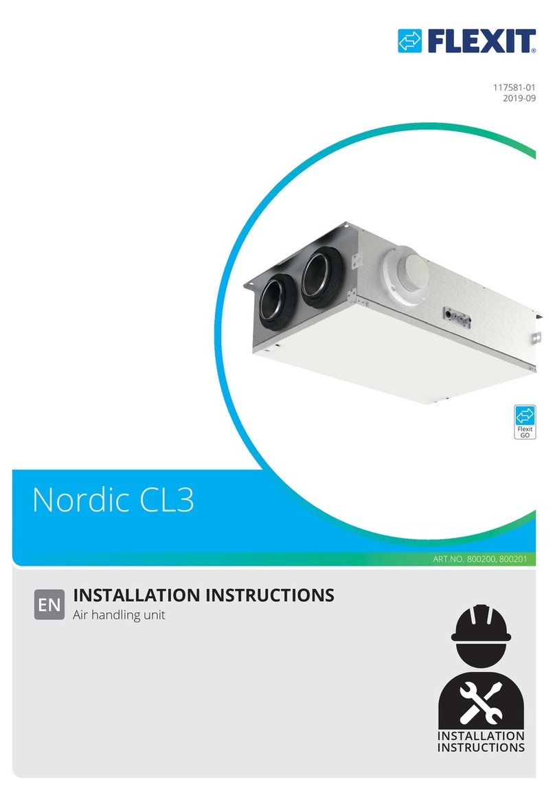
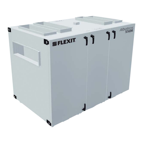
Flexit L4 X User manual


This manual suits for next models
3
Table of contents
Other Flexit Air Handler manuals
Flexit
Flexit Nordic KS3 User manual
Flexit
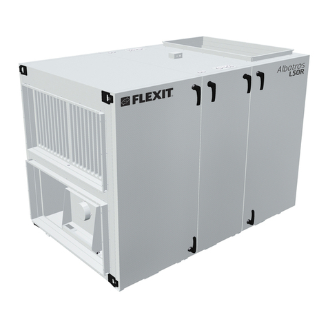
Flexit Albatros L50R Instruction Manual
Flexit
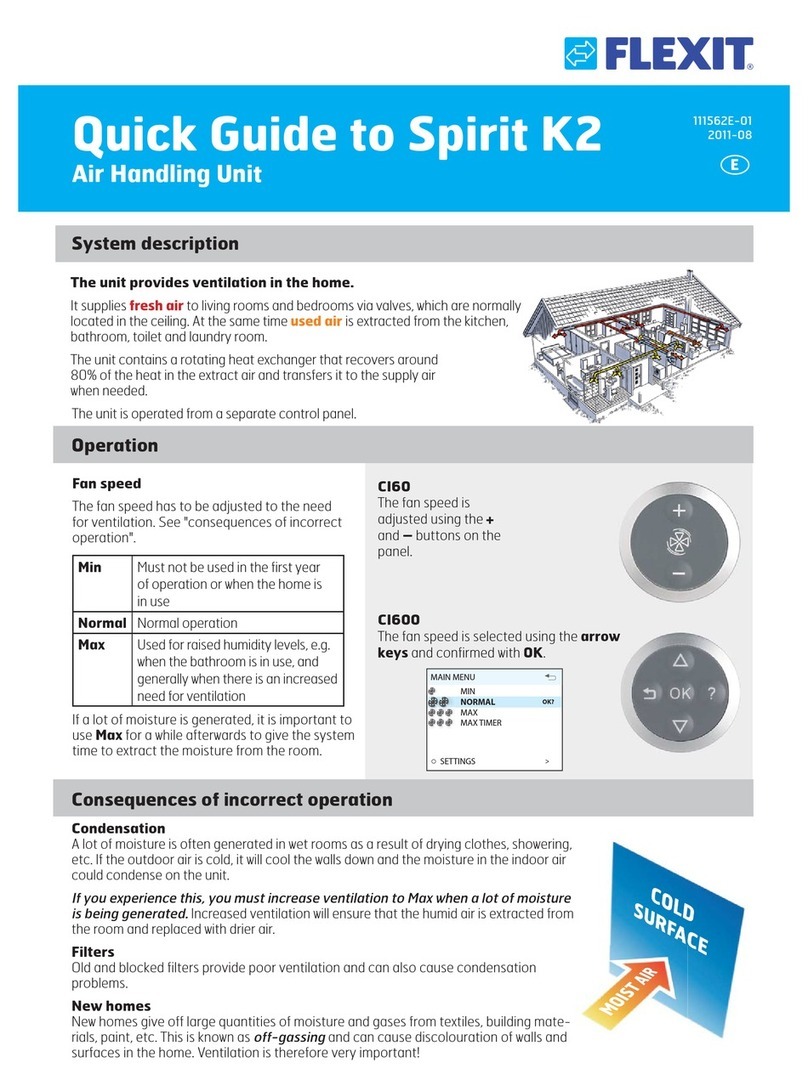
Flexit Spirit K2 User manual
Flexit
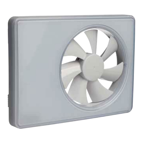
Flexit TEMP User manual
Flexit
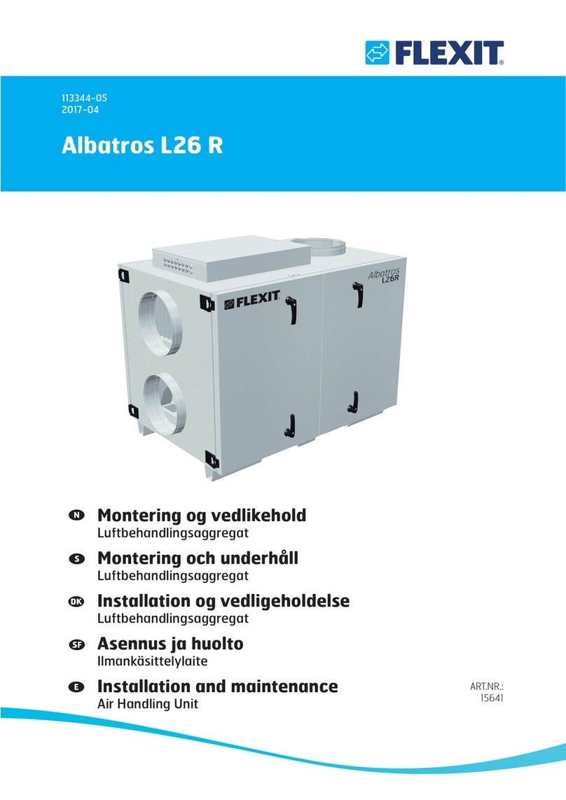
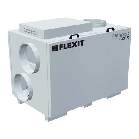
Flexit Albatros L26R Instruction Manual
Flexit
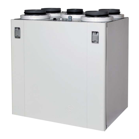
Flexit Albatros L20 R Instruction Manual
Flexit
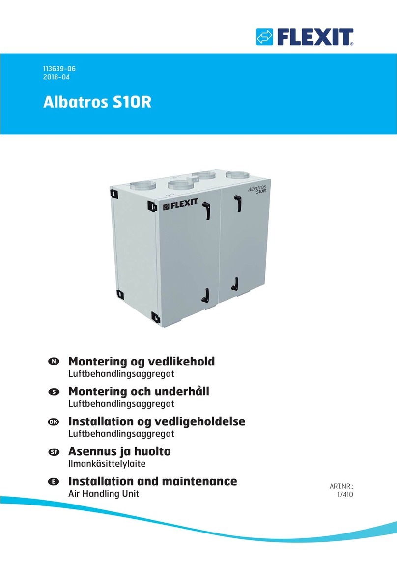
Flexit UNI 3 User manual
Flexit
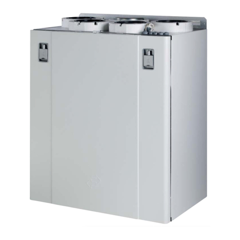
Flexit Albatros S10R Instruction Manual
Flexit
Flexit UNI 2 User manual
Flexit
Flexit Nordic S4 User manual
Flexit
Flexit UNI 4 User manual
Flexit
Flexit 116757 User manual
Flexit
Flexit Nordic S3 User manual
Flexit
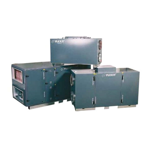
Flexit L12 X User manual

Flexit
Flexit Nordic S3 User manual

Flexit
Flexit Nordic S4 User manual
Flexit
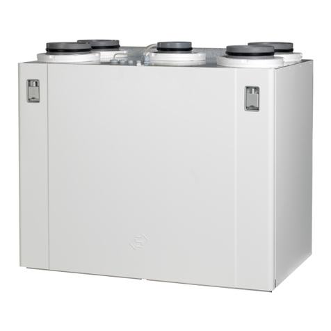
Flexit SPIRIT UNI 4 User manual
Flexit
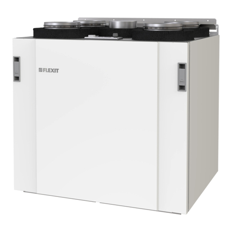
Flexit Nordic S4 User manual

Flexit
Flexit Nordic KS3 User manual
Flexit
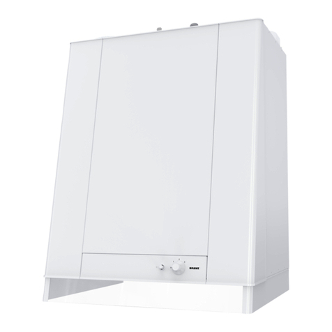
Flexit K2.1 User manual
Popular Air Handler manuals by other brands
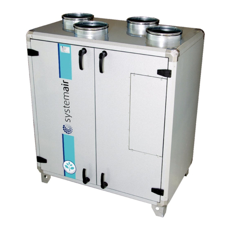
System air
System air Topvex TR Series Operation and maintenance instructions
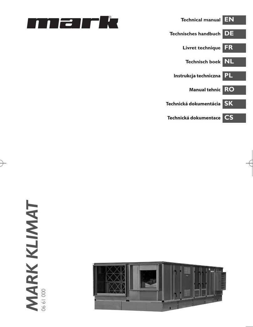
Mark
Mark Klimat 15-15 Technical manual

System air
System air Geniox Core user manual
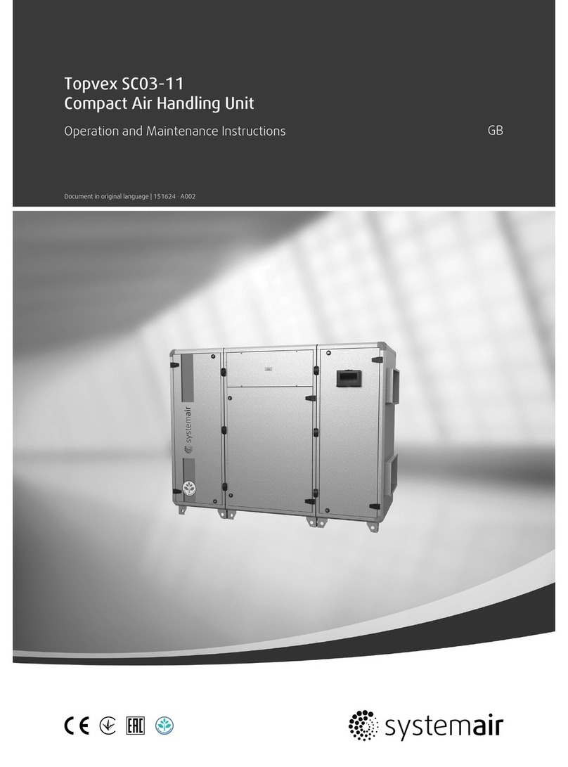
System air
System air Topvex SC03-11 Operation and maintenance instructions

BLAUBERG Ventilatoren
BLAUBERG Ventilatoren BlauAir RP user manual

Salda
Salda RIS 1200 VWL EKO 3.0 QUICK LAUNCH GUIDE
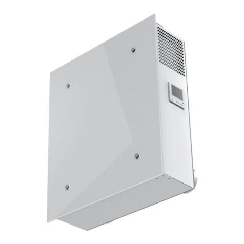
BLAUBERG Ventilatoren
BLAUBERG Ventilatoren Freshbox 100 installation guide
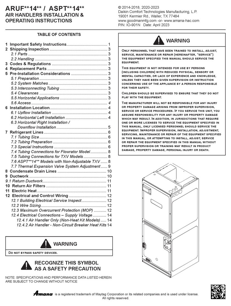
Amana
Amana ARUF 14 Series Installation & operating instructions
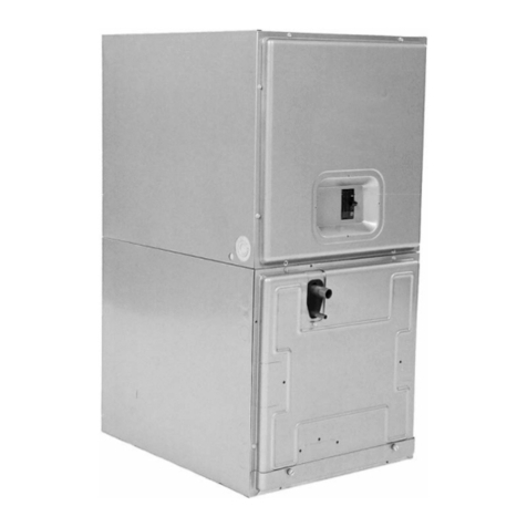
Rheem
Rheem RBHP-17A00NH1 installation instructions
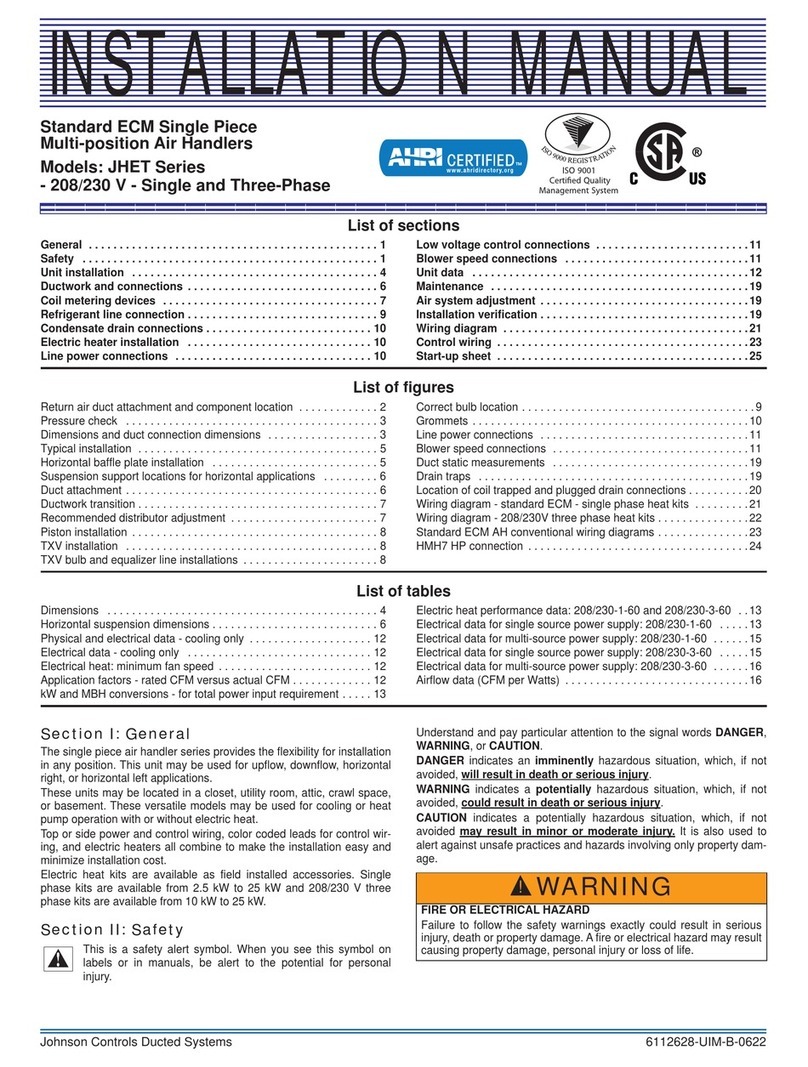
Johnson Controls
Johnson Controls JHET Series installation manual

Gree
Gree GVH24AK-K3DNC6A Service manual
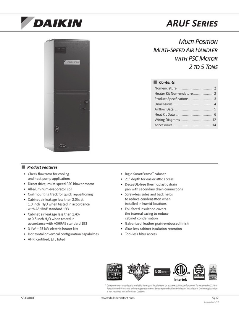
Daikin
Daikin ARUF Series manual
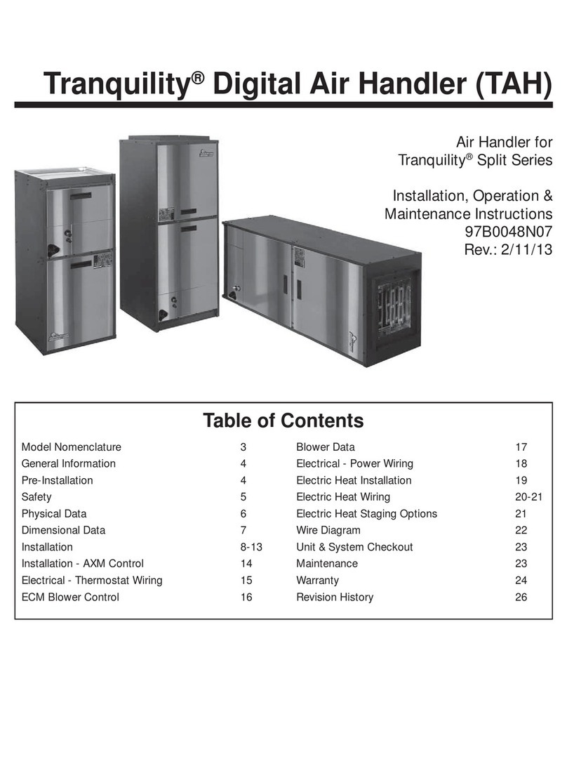
ClimateMaster
ClimateMaster Tranquility Series Installation, operation & maintenance instructions
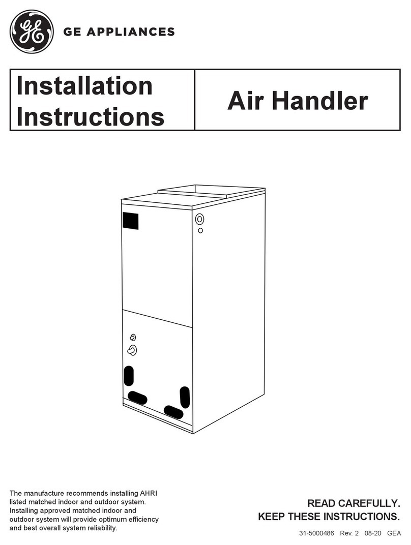
GE
GE UUY24ZGDAA installation instructions
Lennox
Lennox VRF VEAH024C432P installation manual
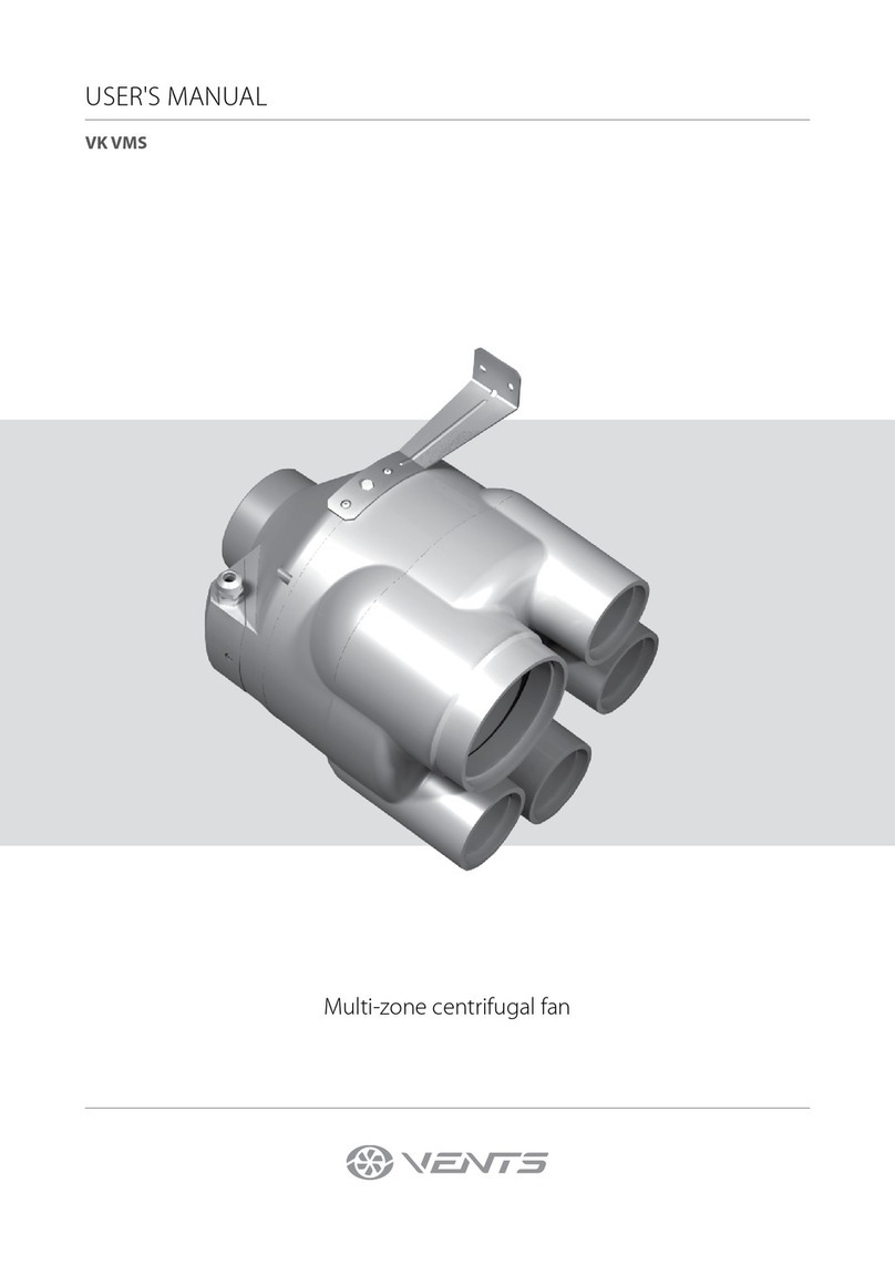
Vents
Vents VK VMS user manual
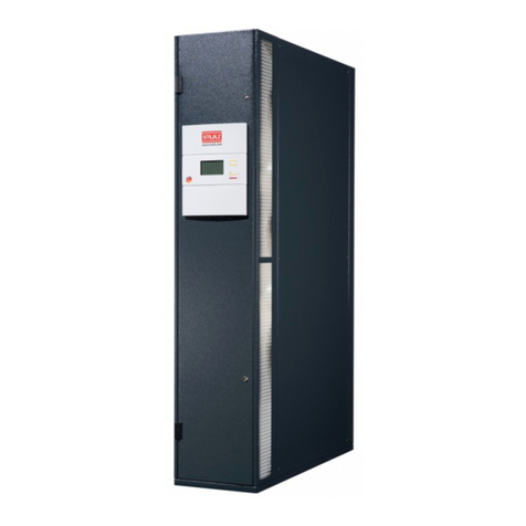
Stulz
Stulz CyberRow CW Series Installation, operation and maintenance manual

Envistar
Envistar Flex ENF Assembly instructions
