manuals.online logo
Brands
  1. Home
  2. •
  3. Brands
  4. •
  5. Whirlpool
  6. •
  7. Microwave Oven
  8. •
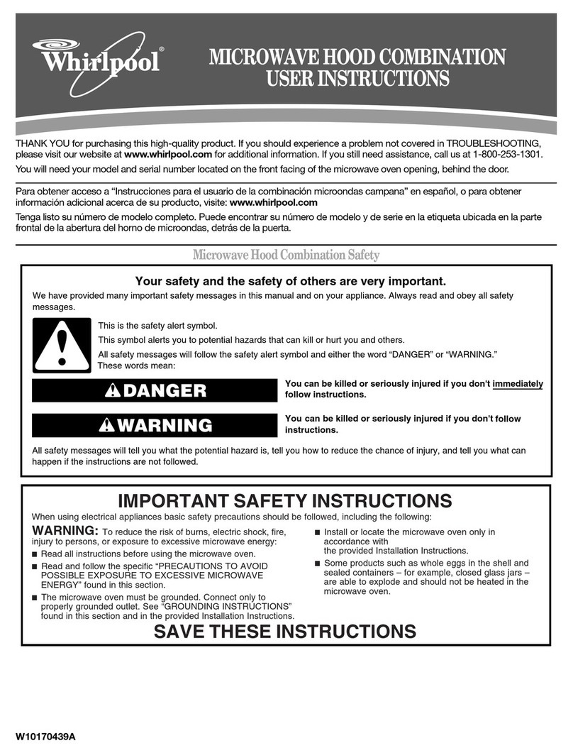
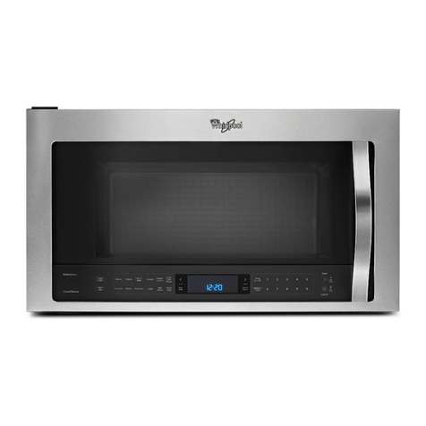
  9. Whirlpool 4619-655-9242114393764 User manual

Whirlpool 4619-655-9242114393764 User manual

Microwave Hood
Combination
Combinacibn De
Horno Microondas
Whatdo I needto
microwavehood?
l
Tools, parts & materials
9Requirements
l
Product dimensions
install the
Whatdo I needto do before I
install the microwavehood?
. Preparemicrowave hood 10
l
Preparecabinet opening 12
The microwave hood is factory setfor ventless
(recirculating) operation. Tovent through the wall
or roof, changesmust madeto the venting system.
Doing so will: Hacerlo:
/ makeinstallation easier. (/ hara masfacil la instalacion.
I/ help you in the future if you havequestions.
ti help if you havean electrical inspection. V’ lo ayudaraen el futuro si tiene alguna pregunta.
ti lo ayudara si tiene una inspection electrica.
Qu6ten o que hater ara
instalar9
a campana el hornoB
microondas?
l
Instrumentos, piezasy materiales 4
. Requisitos 5
l
Dimensiones del product0 5
$Iu6 tengo que hater antesde
mstalar la cam
dana del horno
de microondas.
l
Prepararla campanadel horno de
microondas IO
l
Prepararla abertura en el gabinete 12
Lacampanadel horno esta disehada por la fabrica para
operation sin salida de aire (recirculation). Paraque
hayasalida de aire atraves de una pared o del cielo raso,
deben hacersecambios al sistema de salida de aire.
Xbmo instalo la cam
il
ana
el horno de microon
gas?
. Fijela campanadel horno a la
pared o al gabinete 16
l
Conectela campanadel horno 18
PartNo.4619-655-9242114393764
ParteNo. 4619-655-9242114393764
b-98
Your safety and the safety of
others is very important.
We have provided many important safety message
in this manual and on your appliance.
Always read and obey all safety messages.
q
! This is the safety alert symbol. This symbol
alerts you to hazards that can kill or hurt
you and others. All safety messages will be
preceded by the safety alert symbol and the word
“DANGER” or “WARNING”. These words mean:
You y&l be killed or seriously injured if you
don’t follow instructions.
You can be killed or seriously injured if you
don’t follow instructions.
All safety messages will identify the hazard, tell you
how to reduce the chance of injury, and tell you
what can happen if the instructions are not
followed.
/ observeall governing codesand ordinances.
d install microwave hood as specified in these
instructions or as specified on wall and upper cabinet
templates. It is recommendedthat a qualified
technician install this microwave hood.
d haveeverything you needto properly install
microwave hood.
(/ checkthe microwavehood for damage. If any damage
is evident, Do Not operatethe microwave oven until it
is checkedby an authorized service technician.
(/ placea portion of carton or other heavymaterial
betweenthe microwave hood andthe floor,
countertop or rangetop. Do not usea plastic cover.
/ removeshipping materialsand parts from inside the
microwave oven. Locatetemplatesand setthem aside
to be used later.
/ determinewhich venting methodyou will use.
d makesure the microwavehood will be mounted
against and supported by both aflat, vertical wall and
upper cabinet or other horizontal structure.
Su seguridad y la seguridad de
10s demis es muy importante.
Hemos incluido muchos mensajes importantes de
seguridad en este manual y en su
electrodomestico. Lea y obedezca siempre todos
10s mensajes de seguridad.
0 ! Este es el simbolo de advertencia de
seguridad. Este simbolo le llama la atencion
sobre peligros que pueden ocasionar la
muerte o una lesi6n a usted y a 10sdemtis. Todos
10s mensajes de seguridad iran precedidos por el
simbolo de advertencia de seguridad y la palabra
“PELIGRO” o “ADVERTENCIA”. Estas palabras
significan:
Si no siguen las instrucciones usted morirti o
sufrird una lesi6n grave.
Si no sigue las instrucciones, usted
DUede
morir 0 sufrir una lesi6n grave.
Todos 10s mensajes de seguridad identificaran el
peligro, le informaran coma reducir las
posibilidades de sufrir una lesion y lo que puede
suceder si no sigue las instrucciones.
4 cumplir contodos 10scodigosy reglamentosvigentes.
4 instalarla campanadel horno coma seespecificaen
estasinstrucciones o en lasplantillas de la paredo el
gabinetesuperior.Serecomiendaque un tecnico
calificadoinstalelacampanadel horno.
I/ tenertodo lo quenecesitaparainstalar debidamentela
campana.
/ verificar si la campanaestadahada.Si hayalgun dafio,
NOuseel horno de microondashastaque lo reviseun
tecnico deservicio autorizado.
/ colocarun trozo decarton o cualquierotro material
pesadoentre lacampanadel horno y el piso, la
encimera o la parte superior de la cocina. No use una
cubiertade plastico.
4 quitar 10smaterialesy piezasde envio queestandentro
del horno de microondas.Localicelas plantillasy
apartelasparausarlasposteriormente.
d determinarel metododesalidadeaire quevaa usar.
(/ Asegljresedeque la campanadel horno de microondas
quedeinstaladay apoyadaen una paredvertical 2
ti makesurethe top and rear supporting structure for
the microwave hood will support 150 pounds, plus the
weight of any items placedinside the microwave oven
or upper cabinet.
(/ makesurethe microwave hood will beattachedwith
two lag screwsto a minimum of one, vertical 2” x 4”
wall stud.
/ makesure not to mount the microwave hood to an’
island or peninsula cabinet.
continuedonpage4
planay en un gabinetesuperior o cualquier otra
estructurahorizontal.
J Asegtiresede quela estructuradeapoyosuperiory la
traseraparalacampanadel horno de microondasSean
capacesde resistir 150 libras, m&sel pesode 10s
articulos quesecolocandentro del horno o del gabinete
superior.
ti Asegliresedefijar la campanadel horno de microondas
con dostornillos con cabezacuadradaparamadera
(tornillos deentibacion)a un minim0 de un montantede
paredvertical de 2”x 4”.
c/ Asegliresede no instalar la campanadel horno de
microondasen un gabineteaisladoo peninsular (sin
respaldode pared).
continlia enlapAgina4
3
Tamafioreal
Tamaftoreal
rm Tamaftoreal
continuedfrompage3
Tools and materials
needed
A.
B.
C.
D.
E.
F.
G.
H.
I.
J.
K.
Gloves
Safetyglasses
Measuringtape
Pencil
Maskingtapeor thumb tacks
Scissors
Electricdrill
3/i 6”drill bit
3/8”and3/4”wooddrill bits
Flat-bladescrewdriver
Phillipsscrewdrivers:No.2for powersupply cord clamp
screwand No.3 for l/4” x 3”andl/4” x 2-318”round
headbolts
Tocut 2” diameter power supply cord hole -
L. Keyholesawfor wood cabinetor,
M. 2”diameterholedrill bit for woodor metalcabinet
N. 7/16”nut driver for l/4” x 2” lagscrews
Tocut wail or roof vent opening-
L. Keyholesaw
0. Caulkinggun andweatherproofcaulkingcompound
P. Ducttape
Parts supplied
Q. 4, l/4” X3”boltsand4 spring toggle-heads
(for drywall)
R. 2, l/4” X2-3/8”bolts and2 washers(secure
microwavehoodto cabinet)
S. 4, l/4” X2”lagscrews(for woodstuds)
T. 1 powersupply cordclampand
1 mountingscrew(darkcolored)
U. 1 powersupply cord bushing
Notshown:
Uppercabinetandwall papertemplates
Wall/roofventdamperassembly
Mounting plate(attachedto backof microwavehood)
2 aluminumfilters
2 charcoalfilters
ienedela pAgina3
Herramientas y materiales
que se necesitan
A.
B.
C.
D.
E.
F.
G.
H.
I.
J.
K.
Guantes
Anteojosprotectores
Cintade medir
Lapiz
Cintaadhesivao tachuelas
Tijeras
Taladroelectrico
Brocade barrenade3/l 6”
Brocasdebarrenade3/8” y 3/4” paramadera
Destornilladorde punta plana
DestornilladoresPhillips. No.2 paraprensadetornillo
decabledealimentaciony No.3 parapernos
decabezaredondade i/4” x 3” y l/4” x 2-318”
Parahater un orificio de 2” de diemetro para ei
cable de aiimentaci6n -
L. Sierrade calarparagabinetede maderao,
M. Brocade barrenade2” dediimetro paragabinetede
maderao metalico
N. Llavedetuercade 7/l 6” paratornillos con cabeza
cuadradaparamadera
Parahater un orificio de saiida de aire en la
pared o el cielo raso-
L. Sierradecalar
0. Pistolaparacalafateoy masillaparacalafatear
impermeable
P. Cintaadhesiveparaconductos
Partes provistas
Q. 4 pernosde l/4” x 3” y 4 tuercasacodilladasde
resorte (paramuros interioressin mortero)
R. 2 pernosde l/4” x 2-3/8” y 2 arandelas(parafijar la
campanadel horno al gabinete)
S. 4tornillos con cabezacuadradaparamaderadel/4” x 2”
(paramontantesde pared)
T. 1abrazaderaparacabledealimentaciony un tornillo de
sujecion(color oscuro)
U. 1 manguitoparael cabledealimentacion
No aparecen en las ilustraciones:
Plantillasde gabinetesuperiory depared
Conjuntode lacompuertadel orificio desalidadeaire en
la pared/e1cielo raso
Placade montaje(fijadaa la partetraseradela campanaq
delhorno)
2 filtros dealuminio
2 filtros decarbon
Location
Ubicach
NOTE:Theremustbeat leastonewall studwithincabinetopening.
NOTA:debehaberal menosunmontantedepareddentrode la
30” min. cabinet aberturadel gabinete.
01
3(
la aoenurz
wall studs I
Montantes I
de pared I
I
Checkthe opening wherethe microwave hood will be
installed. The location must provide:
/ 2” X 4” wood studding and 3/8” thickness drywall or
plaster/lath.
/ Support for microwave hood weight of 150 pounds
plus the weight of items placedin the oven or upper
cabinet.
ti 30” wide minimum opening.
/ 14” clearancebetweenthe bottom of microwave hood
and the cooktop.
4 13” recommendedupper cabinet depth to allow for
removal or servicing if needed.
/ Protectionfrom draft areas,such as windows, doors
and strong heating vents.
/ Groundedelectrical outlet. See“Electrical
Requirements,” page6.
continuedonpage6
Product dimensions
Dimensiones del product0
I
16-W
1
Revisela abertura donde se instalara la campanadel
horno. El lugar debetener:
4 Montante de maderade 2” x 4” y muro interior sin
mortero o yesoList6n de maderade 3/8” de espesor.
4 Soporte parael pesode la campanadel horno de 150
libras, rnis el peso de 10sarticulos que se colocan
dentro del horno o gabinete superior.
ti Abertura minima de 30” de ancho.
4 Espaciolibre de 14” entre la basede la campanadel
horno y la encimera.
d Profundidad recomendadade 13” del gabinete
superior para permitir sacarla campana0 repararla0
darle servicio si fuera necesario.
ti Protecci6n contra dreascon corrientes de aire, tales
coma ventanas, puertas y conductos de ventilaci6n
de aire caliente.
(/ Tomacorriente puesto atierra. Ver “Requisitos
El&tricos” en la pigina 6.
continlia enlapagina6
5
.’
3-prong
enchufede puesta
a tierra de tres
terminales
alimentaci
6n wall receptacle
tomacorriente de
pared contres
terminales para puesta
a tierra
Electrical Elhtricos
Electrical Shock Hazard
Plug into a grounded 3-prong outlet.
Do not remove ground prong.
Do not use an adapter.
Do not use an extension cord.
Failure to follow these instructions can result
in death, fire, or electrical shock.
Important: Observe all governing codes and ordinances.
It is the customer’s responsibility:
Tocontact a qualified electrical installer.
Toassure that the electrical installation is adequate
and in conformance with National Electrical Code,
ANSUNFPA70 - latest edition*, and all local codes
and ordinances.
You must have:
4 120-volt, 60Hz,AC-only,15- or 20-amp., fused
electrical supply.
ti outlet locatedin the upper cabinet asclose as
possibleto the microwavehood.
Werecommend:
d atime-delay fuse or circuit breaker.
I/ a separatecircuit serving this appliance only.
If codes permit and a separate ground wire is used, it
is recommended that a qualified electrician determine
that the ground path is adequate.
Ial
*
Peligro de choque electrico
Enchufelo en un tomacorriente de pared de
conexidn a tierra con 3 terminales.
No quite el terminal para conexion a tierra.
No use adaptador.
No use cable de extension.
No seguir estas instrucciones puede ocasionar
la muerte, un incendio o un choque electrico.
Importante: cumpla con todos 10scodigos y
reglamentos vigentes.
Esresponsabilidad del cliente:
Llamar a un tecnico en instalaciones elecricas
calificado para hater la instalacion.
Asegurarse de que la instalacion electrica sea correcta
y adecuada y de acuerdo con el Codigo National de
Energia ANSUNFPA70 - ultima edition’, y todos 10s
codigos y reglamentos locales.
Usted debe tener:
4 Un suministro electrico, protegido por fusible, de 120
voltios, 60 Hertz,solo de CA,de 15 6 20 amperios.
d Untomacorriente de pared ubicado en el gabinete
superior lo mas cercaposible de la campanadel
horno.
Recomendamos:
/ Unfusible de retard0 o un disyuntor.
/ Un circuit0 separadosolo para este aparato
electrodomestico.
Si 10scodigos lo permiten y se usa un cable de puesta
a tierra separado, se recomienda que un electricista
calificado determine si el trayecto de la puesta a tierra
es adecuado.
6
Recommendedgroundmethod
Foryour personal safety,this appliance must be
grounded. This applianceis equippedwith a power
supply cord having a 3-prong ground plug. To minimize
possible shock hazard,the cord must be plugged into a
mating 3-prong ground-type wall receptacle,grounded in
accordancewith the NationalElectricalCode,ANSVNFPA
70 - latest edition*, and all local codesand ordinances.
Copies of the standards listed may be obtained from:
l
Nalional Fire Protection Association
Batlerymarch Park
Ouincy, Massachusetts 02269
Venting
The microwave hood is set for ventless (recirculating)
installation. For wall or roof venting changes to the
venting system must be made.
CAUTION: To reduce risk of fire and to
properly exhaust air, be sure to vent air
outside. Do not vent exhaust air into
spaces within walls or ceilings or into
attics, crawl spaces or garages.
IVEtodorecomendadopara la puestaa
tierra
Parasu seguridad personal este at-tefactodebeser
puesto atierra. Esteat-tefactoestaequipado con un cable
de alimentacion provisto de un enchufe de puestaa tierra
detresterminales.Parareduciral minim0el riesgode
choque electrico, el cabledebeser enchufado en un
tomacorriente de pared del mismo tipo con tres
terminales, puesto a tierra de acuerdo con el Codigo
National de EnergiaANSVNFPA70 - tiltima edition*, y
todos 10scodigos y reglamentos locales.
Copia de las normas indicadas se pueden obtener en:
* National Fire Prelection Association
Batterymarch Park
Quincy, Massachusetts 02269
Salida de aire
Estacampana del horno ha sido disefiada para ser
instalada sin salida de aire (recirculacibn). Para salida
de aire en la pared o en el cielo raso, deben hacerse
cambios en el sistema de salida de aire.
PRECAUCICN: para reducir el riesgo de
incendio y para instalar el sistema de
salida de aire adecuado, asegurese de
que el aire salga al exterior. No ponga la
salida de aire en espacios dentro de
paredes o cielo raso o en aticos,
sotanos de pequeiia altura o garajes.
continuedonpage8 continljaenlapagina8
7
,’
Roofventina
Salida de aire por el cielo raso
roofcao
de 3-114”x 10
Wall venting
Salida de awe por la pared wall cap
caperuz de pared
d
3-W’ x 10” through-the-wall
a travCsde la pared por un
orificio de 3-l/4” x 10
Roundvent transition
Transicih de conduct0de salida de aire redondo
6” min. diameter roundvent
conduct0de salida de aire
redondode 6” de diametro
minim0 elbow
coda
continuedfrompage7 vienedelapAgina7
For wall or roof venting methods:
Choosebetweenroof venting or wall venting.
If the wall exhaust method is chosen, besure that there
is proper clearancewithin the wall for the exhaust vent.
Vent materials needed for installation are not included.
Wall and roof caps must have back-draft damper.
Werecommend:
/ using rigid metalvent.
4 that length of vent and number of elbows should be
keptto a minimum to provide efficient performance.
d that sizeof vent should beuniform.
(/ using duct tapeto sealall joints in the vent system.
(/ using caulking compound to sealexterior wall or roof
opening around cap.
Para metodos de salida de aire a travi% de la pared o
el cielo raso:
Decidaentre instalar la salida de aire a traves del cielo
raso o de una pared.
Si se decide por el metodo de salida de aire a traves de la
pared,asegirresede que haya el espacio adecuadodentro
de la pared parael conduct0 de salida de aire.
No se incluyen 10smateriales del conduct0 de salida
de aire que se necesitan para la instalacion.
Las caperuzas para cielo raso y pared deben tener
compuerta de contratiro.
Recomendamos:
usar un conduct0 de salida de aire metalico y rigido.
aue la longitud del conduct0 de salida de aire y el
(/ two elbows should not beinstalled together.
We do NOTrecommend:
ti flexible metalvent.
NOTE:If flexible metalvent must be used,calculate
eachfoot of flexible metalvent astwo feet of rigid
metalvent. Flexible metal elbows count twice as much
as standard elbows.
numero de codas se mantengana un minim0 para
lograr un rendimiento eficiente.
que las dimensiones del conduct0 Seanuniformes.
usar cinta paraconduct0 para sellar todas las uniones
en el sistema de salida de aire.
usar masilla paracalafatearparasellar la pared
exterior o la abertura en el cielo raso alrededor de la
caperuza.
no se deben instalar dos codas juntos.
No recomendamos:
d conduct0 de salida de aire metalico flexible
NOTA:si debeusarse un conduct0 metdlico flexible,
calcule cadapie de conduct0 metalico flexible coma si
fueran dos pies de conduct0 metalico rigido. Los codas
de metalflexible hacen por dos codas estandar.
3-W” x lfk to 6” roundvent transition
translclbn de conductode sallda de aire
redondode 3-l/4” x 10” a 6”
8
1-1/4’x10”to6=5ft 3-1/4”xlO”roofmp=24fL 3-1/4”xlO
)e3-1/4’xlO”a6= Caperwadecielorasode Welbow=25ft.
i pies 3-W x 10”=24pies Codode90”y 3-W x
10”=25pies
Recommendedstandardfittings
Accesoriosesthdar recomendados
3-W x IO” vent system
Sistema de salida de aire de 3-114”x 10”
3-W x lo”
90’ elbow
Codode 90’ y
3-l/4” x 10”
\fFk i$L de
ti L
6” ventsystem
Sistemade salida de aire de 6”
90” elbows
codade 90”
traniltion
transicidn
Recommendedvent length:
Use3-l/4’ X 10” rectangular or 6” round vent.
Thetotal length of the vent system including straight
vent, elbow,transitions, wall or roof capsmust not
exceedthe equivalent of 140feet of 3-l/4” X 10’
rectangular or 6” diameter round vent.
For best performance, useno morethan three 90 degree
elbows.
Tocalculate the length of systemyou need,addthe
equivalent feetfor eachvent piece used in the system.
Seethe following examples:
3-W x 10” ventsystem:
1 - 3-l/4” x 10”
90” elbow =25ft.
1- wall cap = 40ft.
8 feetstraight = 8ft.
Lengthof
3-l/4” x 10”system = 73ft.
6” ventsystem:
1- transition = 5ft.
2 - 90” elbows = 20ft.
1 - wall cap = 40ft.
8 feetstraight = 8ft.
Lengthof 6” system = 73ft.
If the existing vent is round, a rectangular-to-round
adaptermust be usedand a rectangular3’ extension vent
betweenthe damperassemblyand adaptermust be
installed to prevent damperfrom sticking.
longitud recomendada del conduct0 de salida de aire:
Useun conduct0 de salida de aire rectangular de 3-l/4” x
10” o redondo de 6”.
La longitud total del sistema de salida de aire, incluyendo
el conduct0 de salida de aire recta, el coda, las
transiciones, las caperuzasde pared o cielo raso no
debenexcederel equivalente a 140 pies de conduct0
rectangular de salida de aire de 3-l/4” x 10” o conduct0
redondo de 6” de diimetro.
Paramejoresresultados, no use mAsdetres couos de
90”.
Paracalcular la longitud del sistema que necesita,
agreguela equivalencia en pie paracadapedazode
conduct0 usado en el sistema. Vea10ssiguientes
ejemplos:
Sistema de salida de aire de 3-l/4” x 10”:
1 - Codode90”
y 3-114”x 10”
1 - Caperuzade pared
8 piesrecta
Longituddeun
= 25 pies
= 40 pies
= 8 pies
sistemade 3-l/4” x 10” = 73 pies
Sistema de salida de aire de 6”
1 - transici6n = 5 pies
2 - codas de 90” = 20 pies
1 - caperuzade pared = 40 pies
8 pies recta = 8 pies
Longitud de un
sistema de 6” = 73 pies
Si el actual conduct0 de salida de aire es redondo, debe
usarse un adaptadorde rectangular a redondo y un
conduct0 de extensi6n rectangular de 3” entre el
conjunto de la compuerta y sedebe instalar el adaptador
pareevitar que la compuerta se atasque.
9
Loosentape to open door. Do Not remove tape.
Removecontents from inside microwave oven including
turn table, turn table support and hub.
Completely close door and replace tape so that door
does not swing open while microwave is being handled.
Mounting plateis gray metalplateon backof microwave
hood.
Do not remove screws in mounting plate.
Insert flat-blade screwdriver @ into notches 09 locatedat
top corners of mounting plate0. Usescrewdriverto pry
mounting platefrom microwavehood cabinet. Remove
mounting plateand set aside.
Forventless (recirculating) operation, go to “Prepare
cabinet opening” page12.
Tovent through the wall, go to step 2 then to step 3,
“Wall-venting installation”.
Tovent through the roof, go to step2 then to step 6,
“Roof-venting installation”.
Aflojela cinta paraabrir la puerta. NOquite la cinta.
Saquetodolo queestedentrodel hornode microondas
incluyendola bandejagiratorio, el soportedel Platogiratorio y
el eje.
Cierrela puertacompletamentey vuelva a colocarla cinta
paraquela puertanoseabramientrassetrabajaen el horno.
Laplacademontajeeslaplacamethlicagris queesttienlaparte
traseradelacampanadelhorno.
Noquite 10stornillos de la placade montaje.
lnserteel destornilladordepuntaplanaAenlasmuescasB
ubicadasen lasesquinassuperioresdelaplacademontajeC.
Useeldestornilladorparasacarlaplacademontajedelgabinete
delacampanadelhorno.Quitela placademontajey apartela.
Parafuncionamientosin salida de aire (recirculacibn), vayaa
lasection “Preparelaaberturadelgabinete”en la pagina12.
Parasacarel aire a travesde la pared,vayaal paso2, luegoal
paso3, “lnstalacionconsalidadeairea travesdelapared”.
Parasacarel aire a travesdel cielo raso, vayaal paso2, luego
al paso6, “lnstalacionconsalidadeaireatravesdelcieloraso”.
Remove5 screwsthat attach damperplate @to top of
microwave hood cabinet. Quite10s5tornillos quefijan la placadela compuerta@ a
la partesuperior delgabinetede la campanadel horno.
Keepdamper plateand screwstogether and set aside. Mantengajuntos lacompuertay 10stornillos y apat-telos.
/
/
Rotateair deflector so that deflector vanes 0 will face Deslicecon cuidadoel deflectordeaire0 parasacarlodel
out the rearof the cabinet andthe small exhaust port 0 gabinete.Gireel deflectordeaire demaneraque lasaletasdel
of the air deflectorfacesthe exhaust port 0 in deflector0 quedenorientadashaciala partetraseradel
microwave hood. gabinetey la lumbreradeescapepequeha0 del deflectorde
airequedeorientadahaciala lumbrerade escape0 dela
campanadel horno.
Slide air deflector backinto cabinet asfar as it will go. Deslicecompletamenteel deflectordeaire paravolver a
Checkthat deflector vanes 0 facethe rear of the cabinet colocarloen el gabinete.Verifiquequelasaletasdel deflector
and that the small exhaust ports 0 0 faceeachother. @ quedenorientadashaciala partetraseradel gabinetey que
laslumbrerasdeescapepequenas0 0 quedenorientadasla
unahaciala otra.
10
Reattachdamper plate03with five screws. Vuelvaa fijar la placadela compuet-ta@con cincotornillos.
Carefully slide the air deflector 0 out of the cabinet.
Rotateair deflector so that deflector vanes 0 facethe Deslice con cuidado el deflectordeaire 0 parasacarlodel
top of the cabinet and the small exhaust Port@ of the ah gabinete.Gireel deflectordeaire de maneraque lasaletasdel
deflector facesthe exhaust port in microwave hood 0. deflector0 quedenorientadashaciala par-tesuperior del
gabinetey la lumbreradeescapepequeiia0 del deflectorde
airequedeorientadahaciala lumbreradeescapedela
campanadel horno 0.
Slide air deflector backinto cabinet as far as it will go. Deslicecompletamenteel deflectordeaire paravolver a
Checkthat deflector vanes0 facethe top of the cabinet colocarloenel gabinete.Verifiqueque lasaletasdeldeflector
and that the small exhaust ports 0 0 faceeachother. 0 quedenorientadashaciala partesuperior del gabinetey
que laslumbrerasdeescapepequehas0 @Iqueden
orientadasla una haciala otra.
8.
Reattachdamperplate @ with four screwsat eachcorner
of the damper plate. Savebright-colored tapping screw Vuetvaafijar la pfacadela compuerta03 con cuatrotornittos
for uselater to attach damperassembly. en cadaesquinadelaplacadela compuerta.Guardeel tornillo
deroscadodecoloresbrillantes parausarlo, posteriormente,
parafijar el conjunto de la compuerta.
11
1.
Olsconneczpower supply to outlet. Desconecteel suministro elhctrico del tomacorri
pared.
2.
Put on gloves and safetyglasses. P6ngase10sguantesy 10santeojosprotectores.
3.
Disconnectand movefreestanding rangeto provide Desconectey muevala cocinaautoestableparatenerf&i1
easieraccessor put a protectivecover over a cooktop. accesoo pongaunacubiertaprotectoraen laencimera.
Removeall contents from upper cabinet. Saquetodos 10sobjetosdelgabinetesuperior.
. If front edgeof cabinet is lower than backedge,adjust
top of wall templateto belevel with front edge. 32
_._ _-
*-
6.
Find
and markthe location of all wall studs on wall
template.
If there are no wall studs in the opening area,DONOT
install microwave hood. Consult your building inspector.
Localicey marquela ubicaci6ndetodos 10smontantesde
pareden la plantilla de pared.
Si no haymontantesde pareden el &reade laabertura,NO
instalelacampanadelhorno. Consultecon su inspectorde
construcci6n.
To locatethe paper upper cabinettemplate, measure Paralocalizarla plantilla de pareddel gabinetesuperior,mida
bottom of upper cabinet.Trim the edgesof “A”, “B”, and la basedelgabinetesuperior.Carte10sbordesde“A”, “B” y
“C” on upper cabinettemplate so template will fit on “C en la plantilla del gabinetesuperior demaneraquela
bottom of upper cabinet. If upper cabinet hasa frame and plantilla quepeen la basedel gabinetesuperior.Si el gabinete
the bottom of cabinet is recessed,trim templateto fit superiortiene un marcoy la patte inferior del gabineteesta
inside the recessedarea.Align centerline of upper cabinet empotrada,cotte la plantilla paraquequepedentro delirea
template with centerline of wall template.Tapeor tack to empotrada.Alineela lineacentralde la plantilladel gabinete
cabinet bottom. superiorcon la lineacentraldela plantilla de pared.Fijelacon
cinta o cMvelacontachuelaa la basedel gabinete.
8.
Checkif points“D” and“E”, or “F” and“G” onwalltemplate
areoverawallstud@: If pointsareoverawallstud,drill
3/16”holes.If pointsareoverdrywall,drill 3/4”holes.
Ifthereis not awallstudat points“D” and“E”, or ‘7 and
“G” or atonly onesetof points,find within shadedareas“H”
and“I” the screwpointsclosestto the centerofwall stud(s).
Drill3116”holes@Iinto wall stud(s).Twoor preferablyfour
lagscrewsmust beusedto securemountingplatewall.
Thelocationofyour wallstud(s)maydiffer from what is
shown.
Verifiqueque10spuntos “D” y “E”, o “F” y “G” dela plantilla
deparedestensobreun montantede pared@: si 10spuntos
esthnsobreun montantedepared,hagaorificios de3/16”. Si
10spuntosestansobreun muro interior sin mortero,haga
orificios de3/4”.
Si no hayningljn montantede pareden 10spuntos “D” y “E”,
o “F” y “G”, o ~610en un pardepuntos, localicedentrodelas
ireas sombreadas“H” e “I” 10spuntos paratornillos m&s
cercanosal centrodel montanteo 10smontantesde pared.
Hagaorificios de3/16” @ en el montanteo en 10smontantes
depared.Debenusarsedos o, preferiblemente,cuatro
tornillos decabezacuadradaparamaderaparafijar la placa
demontajede pared.
Susmontantesde paredpodrianestaren lugaresdiferentes
de10squesemuestranen la ilustraci6n.
continuedonpage14 continlia enlapdgina14
13
Usea hole drill or key hole sawto cut a 2” diameter hole
at shadedareamarked“M” on upper cabinettemplate. Useunabrocade barrenao unasierrade calarparahater
un orificio de2” dediametroen el areasombreadamarcada
“M” en la plantilla del gabinetesuperior.
Note: Install a power supply cord bushing around hole if Nota:lnstale un manguitoaisladordel cabledealimentacion
cabinet is metal. alrededordel orificio si el gabineteesde metal.
Drill 3/8’ holes at points “J” and “K” on upper cabinet
template. Thesearefor 2, l/4’ x 2-3/8” round headbolts
and washers usedto secure microwavehood to upper
cabinet.
Hagaorificios de3/S” en 10spuntos “J” y “K” dela plantilla
del gabinetesuperior.Estosorificios son para2 pernosde
cabezaredondade l/4” x 2-3/8” y lasarandelasse usan
parafijar la campanadel horno al gabinetesuperior.
11.
For ventless, removetemplatesand go to “Attach
mounting plateto wall” page15. Keepdamperassembly
for use if microwave hood is everventedthrough wall or
roof.
If venting through the roof, drill 3/4’ hole in one corner
of shadedrectangular areamarked“L” on upper cabinet
template. Usekey hole saw and cut out the shaded
rectangular area. Removeboth templates.
Do Not Install vent at this time. Goto “Attach mounting
plateto wall,” page15.
If venting through the wall, drill 3/4” hole in one corner
of shaded rectangular areamarked“N” on wall template.
Usekey hole saw and cut out rectangular area. Remove
both templates.
Install vent through vent opening in wall.
Usecaulking to sealwall opening around exhaust cap.
Goto “Attach mounting plateto wall,” page 15.
Parainstalacibn sin salida de aire, quite las plantillasy
vayaa “fije la placade montajea la pared”en la pagina15.
Guardeel conjuntodelacompuertaparausarlasi la
campanadel horno llegaa instalarsecon salidadeairea
travesde la paredo del cielo raso.
Si se instala la salida de aire a trav6s del cielo raso, haga
un orificio de3/4” en unaesquinadel arearectangular
sombreadamarcada“L” en la plantilla del gabinetesuperior.
Useunasierradecalary torte el arearectangular
sombreada.Quitelasdos plantillas.
Noinstaleel conduct0desalidadeairetodavia.Vayaa la
section “fije la placade montajea la pared”en la pagina15.
Si se instala la salida de aire a trav6s de la pared, haga
un orificio de3/4” en unaesquinadel arearectangular
sombreadamarcada“N” en la plantilla de pared.Useuna
sierracaladay torte el arearectangular.Quitelas dos
plantillas.
lnstaleel conduct0desalidadeaireatravesdela abertura
en la pared.
Usemasilladecalafatearparasellar la aberturaen la pared
alrededordelacaperuzadesalidadeaire.Vayaa lasection
“Fijela placade montajea la pared”,en la pagina15.
14
i
Insert l/4” x 3’ toggle bolts @ through holes in mounting lnsertepernosacodilladosde i/4” x 3” @ atravesde10s
plate @that matchthe location of the 3/4” holes in the orificios en la placade montaje@ quecoincidancon 10s
drywall. puntosdondeestan10sorificios 3/4” enel muro interior sin
Start a spring toggle nut 0 on the end of eachtoggle mortero.
bolt. Leaveenough spacefor the toggle to go through lnserteunatuercaacodilladade resorte0 en el extremode
wall and open. cadapernoacodillado.Dejeespaciosuficienteparaqueel
tornillo pasea travesdela paredy seabra.
6
Position mounting plate@Ion the wall. Pushtoggle
bolts @ and nuts 0 through the drywall 0. Coloquela placade montaje@Ien la pared.Empuje10s
pernosacodillados@ y lastuercas0 atravesdel muro
interior sin mortero0.
A
Q
I
Fingertighten the toggle bolts @ to makesure toggle
nuts 0 haveopenedagainst drywall 0. Aprietecon 10sdedos10spernosacodilladas@ para
asegurarsedeque lastuercasacodilladosde resotte0 se
hayanabiertocontra el muro interior sin mottero 0.
front edgeof cabinet bottom or cabinetframe,securely
tighten lag screws and toggle bolts. maderadela pared.Aseguresedequela partesuperiordela
placademontajeestealineadacon el bordedelanterodela
basedel gabineteo del marcodel gabinete,aprietebien 10s
tornillos decabezacuadradaparamaderay 10spernos
acodillados.
15
.. ,
1.
Placea washer on eachl/4” x 2-3/8” bolt and placeinside
upper cabinet by the 3/8” holes.
Ventless or roof venting: Go to Step 3.
Coloqueunaarandelaencadapernodel/4” x 2-3/a” y coldquela
dentrodelgabinetesuperiorcercade10sorificiosde3/8”.
Para instalacidn sin salida de aire o con salida a trav6s del
cielo raso: vaya al Paso 3.
2.
@-
Wall venting installation: Instalacibn con salida a traves de la pared:
Checkthat damper blade@ is on top of tab @Iand Verifiquequela hojadela compuerta@ est6sobrela
movesfreely. Push damperassembly0 through opening lengiieta@ y se puedamoverlibremente.Empujeel conjunto
in mounting plate@9so that tabs in damper assembly dela compuerta0 a trav6sde la aberturaen la placade
lock damperassemblyagainst mounting plate. Long tab montaje@ paraque laslengijetasen el conjunto de la
0 of damperassembly must beto left. compuertafijen el conjuntode la compuertacontra la placa
demontaje.Lalengijetalarga0 del conjunto de la
compuertadebequedara la izquierda.
Excessive Weight Hazard Peligro de peso excesivo
Use two or more people to move and install DOS o m5s personas deben trasladar e instalar la
microwave hood. campana del horno de microondas.
Failure to do so can result in back or other No seguir esta instruccibn puede ocasionar
injury. lesi6n en la espalda u otro tipo de lesi6n.
Makesure the oven door is completely closed and taped
shut.
Carefully lift microwave hood and hang it on support
tabs 0 at the bottom of mounting plate.
Asegtiresedequela puertadel horno estCcompletamente
cerraday fijadacon cintas.
Levantecon cuidadola campanadel horno y cu6lguelade las
lengijetasdesoporte@ en la parteinferior de la placade
montaje.
Rotatefront of microwavecabinet downward. Thread
power supply cord through the power supply cord hole
in the bottom of the upper cabinet.
Girela pat-tedelanteradel gabinetedel horno haciaabajo.
Paseel cabledealimentacibnpor el orificio parael cablede
alimentacibnen la basedel gabinetesuperior.
5.
Rotatemicrowave hood up towards cabinet. Push
microwave hood against mounting plate until locking
pins 0 snap into cabinet.
NOTE:
This will support the microwavehood until the
2-l/4” x 2-3/8” bolts inside the upper cabinet are
installed.
Girela campanadel horno haciaarribaen direcci6ndel
gabinete.Empujela campanacontra la placade montaje
hastaquelasclavijasde retenci6n0 quedeninsertadasenel
gabinete.
NOTA:
estosujetartila campanadel horno demicroondas
hastaquese instalen10spernosde 2-l/4” x 2-3/W dentrodel
gabinetesuperior.
16
6.
Checkthe spacingon eitherside
of microwavehood.
If microwavehoodneedsto beadjusted:
. If filters 0 areinstalled,pushin attabandslidefilter to
the outsideedgeto remove.
l
Removetwo screws0 fromtop of microwavehood
cabinetlocatedclosestto thefront corners.Donot
removescrewslocatedtowardsthe centerof cabinet.
l
Removefront grille 0. Set screws and grille aside.
l
Graspmicrowavehoodsupports@ andfirmly pull
microwavehoodforwardanddownwardto release
microwavehoodcabinetfrom mountingplate
locking pins.
. Graspmicrowavehoodcabinet.Rotatemicrowavehood
downward.Lift off of mountingplate.Setmicrowavehood
asideon a protectedsurface.
l
Loosenmountingplatescrews.Adjustmounting plateand
retightenscrews,
. Reinstallmicrowavehood.
Attach microwave oven with bolts as shown.
Failure to do so can result in broken bones,
Whenmicrowavehoodis
centered,insert bolts0 through
uppercabinetinto microwave
hood.Tightenbolts until thereis
no gapbetweenuppercabinet
andmicrowavehood.
Sisenecesitaacomodarla campanadel horno:
l
Si 10sfiltros 0 estaninstalados,empujepor la lenguetay
desliceel filtro haciael bordeexterno paraquitarlo.
l
Quitedostornillos 0 dela partesuperior del gabinetede la
campanadel horno queestenmascercade lasesquinas
delanteras.Noquite 10stornillos queestdncolocadoshacia
el centrodelgabinete.
l
Quitela rejilladelantera0. Aparte10stornillos y la rejilla.
l
Sujete10ssoportesdela campanadel horno @Iy jalecon
firmezala campanadel horno haciaadelantey haciaabajo
paradesprenderel gabinetede la campanadel horno delas
clavijasderetention dela placade montaje.
l
Sujeteel gabinetedela campanadel horno. Girela campana
delhorno haciaabajo.Levantela placade montajepara
sacarla.Coloquela campanadel horno en unasuperficie
protegida.
l
Afloje10stornillos de la placade montaje.Ajustela placade
montajey vuelvaa apretar10stornillos.
l
Vuelvaa instalar la campanadel horno.
Peligro de caida del aparato
Fije el horno de microondas con pernos, coma se
muestra.
No hacerlo puede ocasionar fractura de huesos,
heridas u otro tipo de lesi6n.
hayaningun espacioentreel
gabinetesuperiory la campana
del horno.
17
1.
Wall venting or recirculating venting: Goto step 2.
Roof-venting installation: Checkthat damper blade@ is
on top of tab 03 and movesfreely.
Insert damperassemblythrough cabinet opening 0 so
that long tab @ slides under the raisededgeof damper
plate.Attach short tab to damperplatewith bright
tapping screw not usedto attach damperplate.
Align damper/vent connector with damperassemblyon
top of microwave hood and attach. Install vent through
vent opening in upper cabinet.
Usecaulking compound to sealroof opening around
exhaust cap.
Salida de aire a travb de la pared o sin salida de aire
(recirculacih): vayaal Paso2.
lnstalacidn consalida de aire a travhs del cielo raso:
verifiqueque la hojadela compuerta@ estesobrela
lengijeta@ y se puedamoverlibremente.
lnserteel conjuntode la compuertaatravesde laabertura
delgabinete0 demaneraque la lenguetalarga@ sedeslice
debajodel bordelevantadode la placade la compuerta.Fije
la lenguetacotta a la placade la compuertacon el tornillo de
roscadobrillante queno seus6 parafijar la placadela
compuerta.
Alineela compuerta/elconectordel conduct0desalidade
airecon el conjuntode lacompuertasobrela campanadel
hornoy fijela. lnstaleel conduct0desalidadeaireatravesde
laabet-turadesalidadeairedel gabinetesuperior.
Usemasilladecalafatearparasellar la aberturaen el cielo
rasoalrededordela caperuzadesalidadeaire.
Coil power supply cord through clamp 0. Secureclamp Enrolleel cabledealimentacionen laabrazadera0. Fijela
to cabinet side wall with dark colored screw. abrazaderaa la paredlateraldel gabinetecon el tornillo
oscuro.
Insert charcoalfilter betweenthe two flanges0 at the lnset-teel filtro decarbonentre lasdosalas0 en la parte
backof the opening. Pushthe filter backagainstspring 0. traseradelaabettura.Empujeelfiltro contrael resot-te0.
Swingthe filter up and pull it forward betweenthe two Desliceel filtro haciaarribay jaleloentre lasdosalasen la
flangesat the front of the opening. Repeatfor other filter. partedelanteradela abertura.Repitael procedimientoparael
otro filtro.
18
Graspaluminum filter screen bythe tab 6 and insert tab
end of filter into cabinet opening. Slidetowards the
center of microwave hood. Insert other end of filter into
opening and slide entire filter towards the side of the
microwave hood until filter is securely in position. Repeat
for other filter.
Removetape from door.
Goto step 6.
Sujetela malladelfiltro dealuminio por la lengueta0 e
inserteel extremode la lenguetadel filtro en laaberturadel
gabinete.Deslicelohaciael centro de la campanadel horno.
lnserteel otro extremodel filtro en la aberturay deslicetodo
el filtro haciael ladode la campanadel horno hastaqueel
filtro quedebienaseguradoen su lugar.Repitael
procedimientoparael otro filtro.
Quitela cinta adhesivade la puerta.
Vayaal Paso6.
end of filter into cabinet opening. Slidetowards the
center of microwave hood. Insert other end of filter into Sujetela pantalladelfiltro dealuminio por la lengueta0 e
opening and slide entire filter towards the side of the inserteel extremodela lenguetadelfiltro en laaberturadel
microwave hood until filter is securely in position. Repeat gabinete.Deslicelohaciael centro de lacampanadel horno.
for other filter. lnserteel otro extremodelfiltro en laabet-turay deslicetodo
el filtro haciael ladodela campanadel horno hastaqueel
Removetape from door. filtro quedebien aseguradoensu lugar.Repitael
Goto step 6. procedimientoparael otro filtro.
Quitelacintaadhesivadela puerta.
Vayaal Paso6.
6.
Plug power cord into grounded outlet.
Reconnectpower supply. Enchufeel cabledealimentacionen el tomacorrientepuestoa
tierra.Vuelnaa conectorel suminstrodeenergia.
7.
Readthe Useand CareGuide,then checkthe operation of Leael Manualde Usey Cuidado,luegoverifiqueel
microwave hood. funcionamientode la campanadesalidadeaire del horno de
microondas.
19
- Filler panel -
Panelesde relleno
Part No.4619-655-9242114393764
ParteNo.461g-655-9242114393764
. Checkthatthe circuit breakeris nottripped or the house
fuseblown.
l
Checkthatthe powersupply cord is pluggedinto the wall
receptacle.
l
Seethe Useand CareGuidefor troubleshooting
checklist.
Checkyour UseandCareGuidefor atoll-free numberto
call, or callthe dealerfrom whomyou purchasedthis
appliance.Thedealeris listed in the YellowPagesofyour
phonedirectory under“Appliances- Household- Major
- Serviceand Repair.”
Whenyou call,you will needthe microwaveovenhood
modelandserialnumber.Bothnumberscanbefound on
the model/serialrating platedlocatedbehindthe microwave
ovendoor on the front frameofthe microwaveovenhood.
Accessory kits
FillerPanelkit no. 4378403- Almond
4158439- White
4158311- Black
Fillerpanelkits areavailablefrom your dealerto usewhen
installingthis microwaveovenin a 36”- or 42”-wide
opening.Thefiller panelsincludedcomein pairsandeach
panelis 3” wide.
Seeyour dealerfor details.
Benton Harbor,Ml 49022
l
Verifique que no se haya botado el interruptor de
circuit0 o que no se hayafundido un fusible.
l
Verifique que el cable de alimentacion este
enchufodo en el tomacorriente de pared.
l
Consulte la section de “Diagnostic0 de problemas”
en el Manual de Usoy Cuidado.
Busqueen el Manual de Uso y Cuidado el nlimero
parallamadasgratis o llame al distribuidor que le
vendio este aparatoelectrodomestico. Eldistribuidor
apareceen las PaginasAmarillas de su gufa telefonica
bajo Electrodomesticos (Appliances) - Efectos
Electrodomesticos(Household) - Electrodomesticos
Grandes(Major) - Servicios y Reparaciones(Service
and Repair).
CuandoIlame,tenga a mano el nljmero del modelo y
el nlimero de serie de la campanade salida de aire del
horno de microondas. Ambos nlimero se encuentran
en la placade clasificacion de modelo/serie que se
encuentra detras de la puerta del horno de microondas
en el marco delantero del horno de microondas.
Juego de accesorios
Panelde relleno juego no. 4378403 - Almendra
4158439 - Blanc0
4158311 - Negro
Puedeobtener juegos de panelesde relleno del
distribuidor de su localidad, para usarlos cuando
instale el horno de microondas en una abertura de
36” - 42” de ancho. Los panelesde relleno vienen en
paresy cadauno tiene 3” de ancho.
Pidadetalles a su distribuidor.
-9
Printed in U.S.A.
impreso en 10sEE.UU.
.’ 6...

Other Whirlpool Microwave Oven manuals

Whirlpool MT4078SPB2 User manual

Whirlpool

Whirlpool MT4078SPB2 User manual

Whirlpool MWO 730 SL User manual

Whirlpool

Whirlpool MWO 730 SL User manual

Whirlpool MCB790XT User manual

Whirlpool

Whirlpool MCB790XT User manual

Whirlpool GH8155XM User manual

Whirlpool

Whirlpool GH8155XM User manual

Whirlpool UMV2186AA User manual

Whirlpool

Whirlpool UMV2186AA User manual

Whirlpool Cook30 User manual

Whirlpool

Whirlpool Cook30 User manual

Whirlpool VM11D-8P Guide

Whirlpool

Whirlpool VM11D-8P Guide

Whirlpool UDT518SAHP User manual

Whirlpool

Whirlpool UDT518SAHP User manual

Whirlpool MWO 616/01 SL User manual

Whirlpool

Whirlpool MWO 616/01 SL User manual

Whirlpool MAX 16/WH/2 User manual

Whirlpool

Whirlpool MAX 16/WH/2 User manual

Whirlpool 8205144 User manual

Whirlpool

Whirlpool 8205144 User manual

Whirlpool WOC97ES0ES User manual

Whirlpool

Whirlpool WOC97ES0ES User manual

Whirlpool Ni-l30 User manual

Whirlpool

Whirlpool Ni-l30 User manual

Whirlpool MT1066XB User manual

Whirlpool

Whirlpool MT1066XB User manual

Whirlpool MT4155SPB2 User manual

Whirlpool

Whirlpool MT4155SPB2 User manual

Whirlpool JT 366 SL User manual

Whirlpool

Whirlpool JT 366 SL User manual

Whirlpool AMW423/IX User manual

Whirlpool

Whirlpool AMW423/IX User manual

Whirlpool MT1130SG User manual

Whirlpool

Whirlpool MT1130SG User manual

Whirlpool YMH2175XSS4 User manual

Whirlpool

Whirlpool YMH2175XSS4 User manual

Whirlpool MT9160XY User manual

Whirlpool

Whirlpool MT9160XY User manual

Whirlpool COMPACT EASYTRONIC MWD240 User manual

Whirlpool

Whirlpool COMPACT EASYTRONIC MWD240 User manual

Whirlpool AMW 515 Operating and maintenance manual

Whirlpool

Whirlpool AMW 515 Operating and maintenance manual

Whirlpool MW88OOXR User manual

Whirlpool

Whirlpool MW88OOXR User manual

Whirlpool MK1074XHQ User manual

Whirlpool

Whirlpool MK1074XHQ User manual

Popular Microwave Oven manuals by other brands

Haier MWG7036RW owner's manual

Haier

Haier MWG7036RW owner's manual

LG MV1610WW Owner's manual & cooking guide

LG

LG MV1610WW Owner's manual & cooking guide

Cafe XC042AYYGEW owner's manual

Cafe

Cafe XC042AYYGEW owner's manual

Sharp R-350A Operation manual

Sharp

Sharp R-350A Operation manual

Panasonic NN-SD973S operating instructions

Panasonic

Panasonic NN-SD973S operating instructions

Sharp R-677 Operation manual with cookbook

Sharp

Sharp R-677 Operation manual with cookbook

Cata BM25GBK instruction manual

Cata

Cata BM25GBK instruction manual

Hoover HMG 280 X User instructions

Hoover

Hoover HMG 280 X User instructions

Hotpoint MWH434AX Instructions for use

Hotpoint

Hotpoint MWH434AX Instructions for use

Samsung SMH7174WE Service manual

Samsung

Samsung SMH7174WE Service manual

Samsung MW614ST-B owner's manual

Samsung

Samsung MW614ST-B owner's manual

Emerson MW8773SL owner's manual

Emerson

Emerson MW8773SL owner's manual

Electrolux EMS2340Si user manual

Electrolux

Electrolux EMS2340Si user manual

Merrychef MC-SERIES Service manual

Merrychef

Merrychef MC-SERIES Service manual

Daewoo KOR-1A1G0A Service manual

Daewoo

Daewoo KOR-1A1G0A Service manual

Pelgrim MAG528RVS Instructions for use

Pelgrim

Pelgrim MAG528RVS Instructions for use

Franke FMW 250 CR G Instructions for using

Franke

Franke FMW 250 CR G Instructions for using

Electrolux EMS28 20 user manual

Electrolux

Electrolux EMS28 20 user manual

manuals.online logo
manuals.online logoBrands
  • About & Mission
  • Contact us
  • Privacy Policy
  • Terms and Conditions

Copyright 2025 Manuals.Online. All Rights Reserved.