White Rodgers 37-5148B User manual

PART NO. 37-5148B
Replaces 37-5148A
9607
Printed in U.S.A.
WHITE-RODGERS DIVISION
EMERSON ELECTRIC CO.
9797 REAVIS ROAD
ST. LOUIS, MISSOURI 63123-5398
PRECAUTIONS
DESCRIPTION
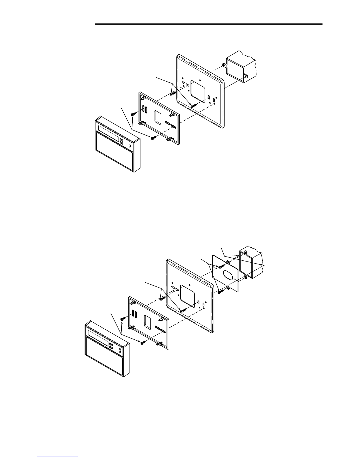
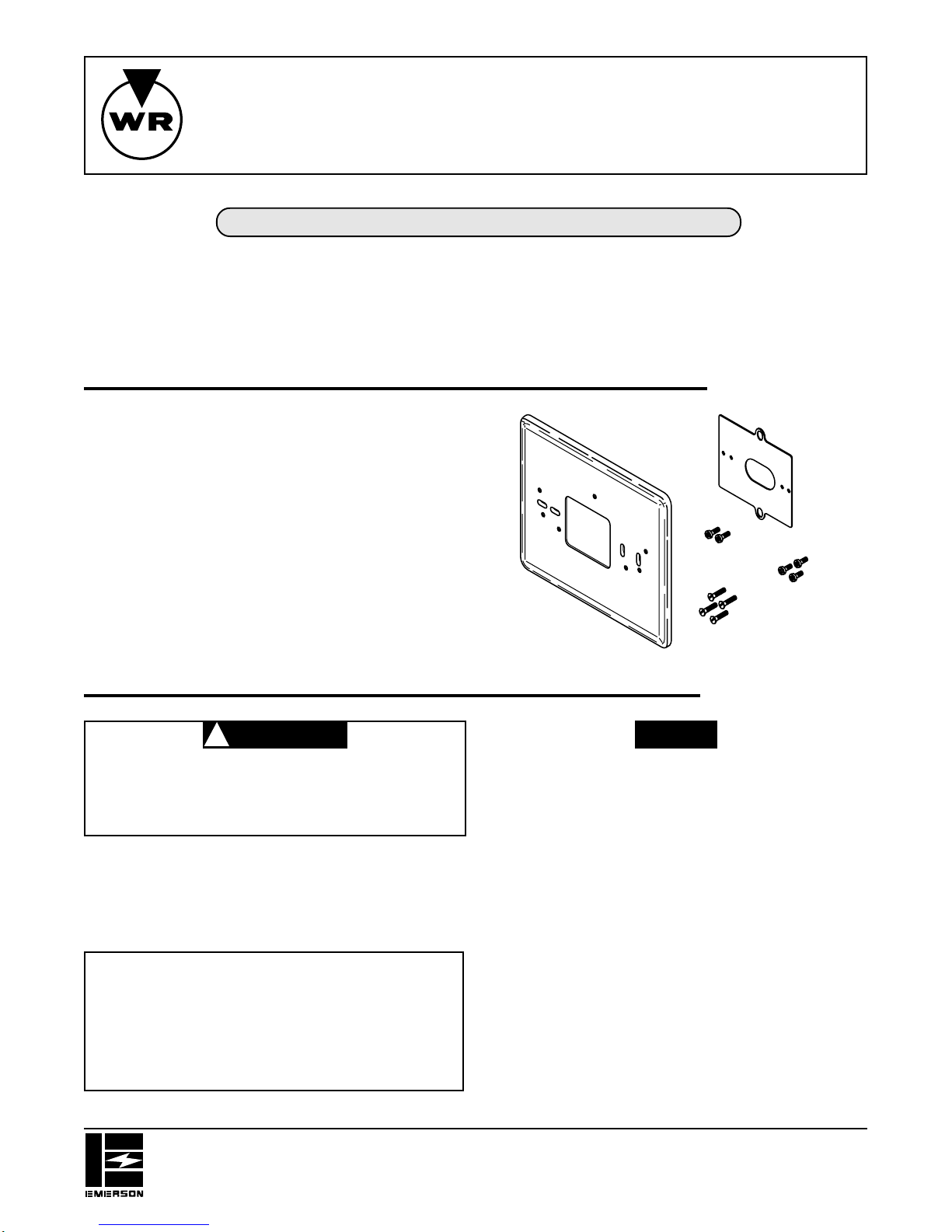
This adaptor plate assembly is designed for mounting a
1F6X, 1F7X, or 1F9X series thermostat to the wall or to a
junctionbox.Thewallcoverplatecoversthejunctionbox,
wall damage, or old thermostat markings. The adaptor
plateisdesignedtoallowhorizontalthermostatmounting,
regardless of junction box orientation.
All kits may not have adaptor plate or all screws shown.
Wall Cover
Plate
Adaptor Plate
No. 6 X 5
⁄
16” Phillips
pan-head screw (2)
6-19 X 3
⁄
8” Phillips
pan-head screw (3)
6-32 X 3
⁄
4” flat-head
machine screw (4)
FAILURE TO READ AND FOLLOW ALL INSTRUCTIONS CAREFULLY
BEFOREINSTALLINGOROPERATINGTHISCONTROLCOULDCAUSE
PERSONAL INJURY AND/OR PROPERTY DAMAGE.
CONTENTS
Description......................................................... 1
Precautions........................................................ 1
Installation.......................................................... 2
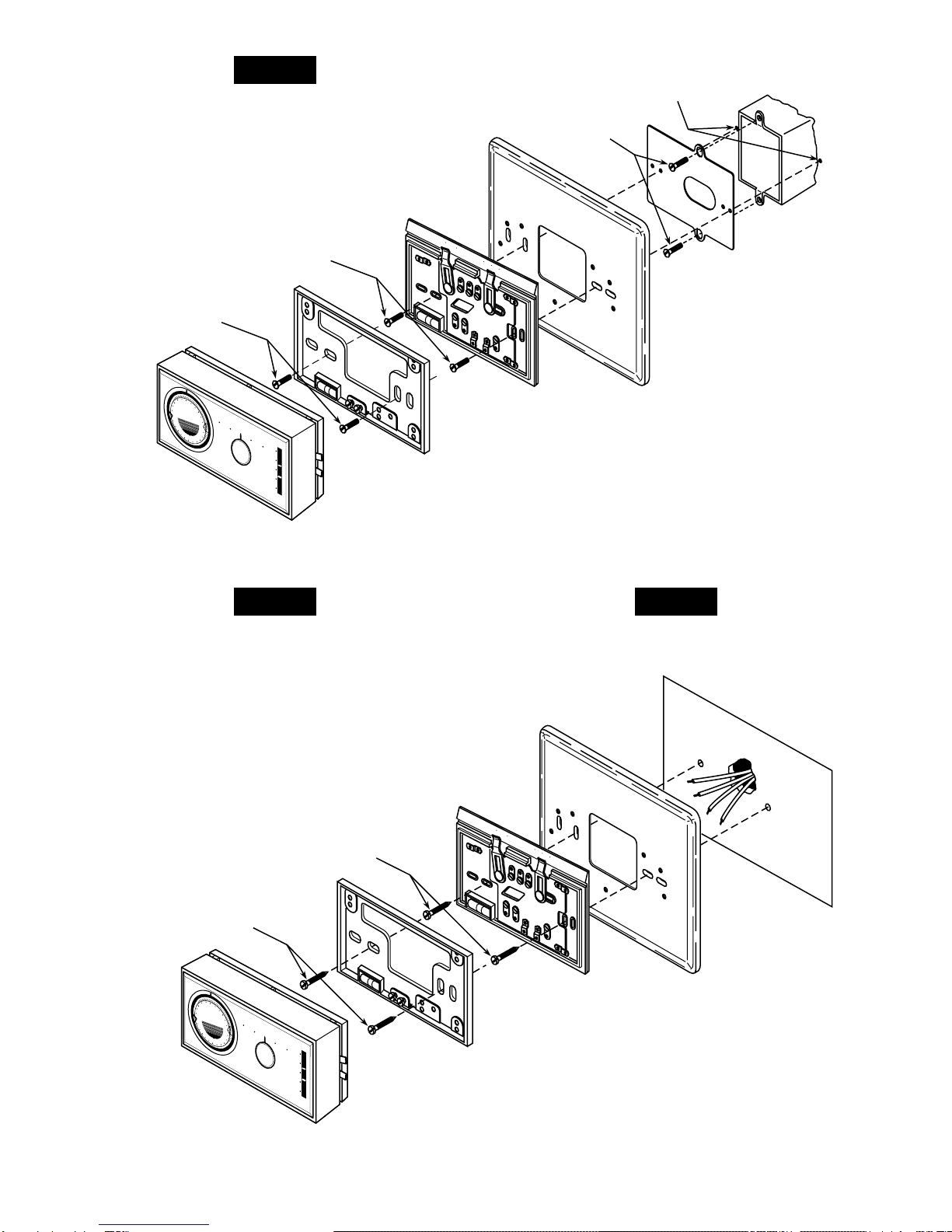
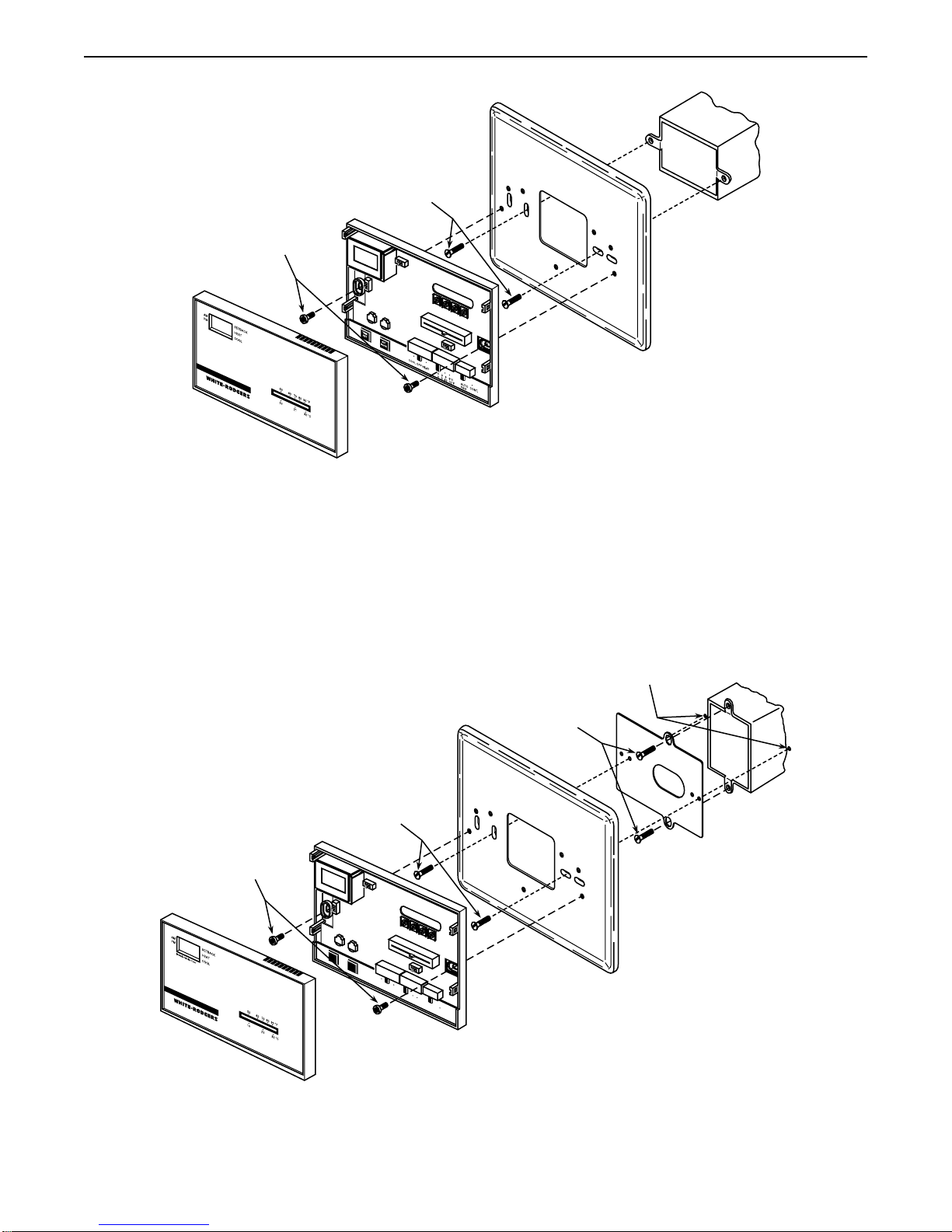
For 1F9X Digital Thermostats
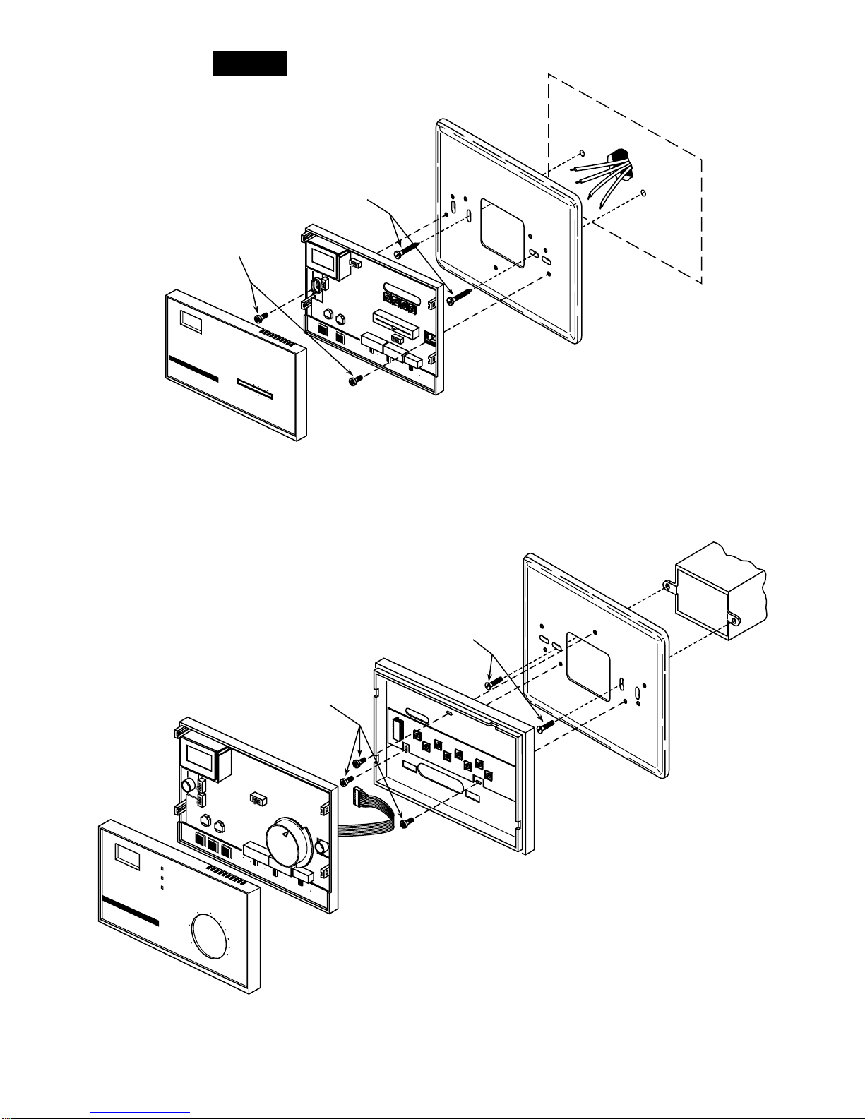
For 1F7X Quartz Clock Thermostats
For 1F6X Thermostats
WHITE-RODGERS INSTALLATION INSTRUCTIONS
Operator: Save these instructions for future use!
F61 Series
Adaptor Plate Assembly
To prevent electrical shock and/or equip-
ment damage, disconnect electrical power
at main fuse or circuit breaker until installa-
tion is complete.
This instruction sheet is not intended as a wiring guide.
Refer to the thermostat installation instructions to ensure
proper wiring.
NOTE
CAUTION
!

2
INSTALLATION
Thermostat
Thermostat Subbase
(may have 2, 3, or
4 mounting holes)
Wall Cover Plate
Junction Box
Figure 1. Mounting 1F9X digital thermostat to horizontal junction box
No. 6 X
5
⁄
16
” Phillips
pan-head screws
6-32 X
3
⁄
4
” flat-head
machine screws
Thermostat
Thermostat Subbase
(may have 2, 3, or
4 mounting holes)
Wall Cover Plate
Junction Box
Adaptor Plate
Figure 2. Mounting 1F9X digital thermostat to vertical junction box
No. 6 X
5
⁄
16
” Phillips
pan-head screws
6-32 X
3
⁄
4
” flat-head
machine screws
Locate and drill two
clearance holes in wall
6-32 X
3
⁄
4
” flat-head
machine screws
FOR 1F9X DIGITAL THERMOSTATS

3
NOTE
Wall Cover Plate
Figure 3. Mounting 1F9X digital thermostat to wall
Wall
Thermostat
Thermostat Subbase
No. 6 X 1” pan-head screws
(supplied with thermostat)
Wall Cover Plate
Junction Box
50 60 70 80 90
9
1
2
3
6
9
1
2
3
6
DAY
90
80
70
60
50
HI
LO
Thermostat
AUTO OFF
FAN
ON
SYSTEM
COOL HEAT
Thermostat
Subbase*
Wall Mounting
Plate*
Figure 4. Mounting 1F7X quartz clock thermostat to horizontal junction box
6-32 X
3
⁄
4
” flat-head
machine screws
*Do not use both subbase and wall
mounting plate – see note, above.
6-32 X
3
⁄
4
” flat-head
machine screws
Wheninstallingwallcoverplateandthermostatdirectlyto
wall,usethepointedscrewssuppliedwiththethermostat.
FOR 1F7X QUARTZ CLOCK THERMOSTATS
Do not install the wall mounting plate and subbase at the
sametime.Thethermostatwillnotoperateproperlyifboth
wall mounting plate and subbase are installed.
NOTE

4
Wall Cover Plate
50 60 70 80 90
9
1
2
3
6
9
1
2
3
6
DAY
90
80
70
60
50
HI
LO
Thermostat
AUTO OFF
FAN
ON
SYSTEM
COOL HEAT
Thermostat
Subbase*
Wall Mounting
Plate*
Junction Box
Adaptor Plate
Figure 5. Mounting 1F7X quartz clock thermostat to vertical junction box
6-32 X
3
⁄
4
” flat-head
machine screws
6-32 X
3
⁄
4
” flat-head
machine screws
*Do not use both subbase and wall
mounting plate – see note, above.
Locate and drill two
clearance holes in wall
6-32 X
3
⁄
4
” flat-head
machine screws
50 60 70 80 90
9
1
2
3
6
9
1
2
3
6
DAY
90
80
70
60
50
HI
LO
Thermostat
AUTO OFF
FAN
ON
SYSTEM
COOL HEAT
Thermostat
Subbase*
Wall Mounting
Plate*
Wall
Figure 6. Mounting 1F7X quartz clock thermostat to wall
No. 6 X 1” pan-head screws
(supplied with thermostat)
Wall Cover Plate
*Do not use both subbase and wall
mounting plate – see note, above.
No. 6 X 1” pan-head screws
(supplied with thermostat)
Do not install the wall mounting plate and subbase at the
sametime.Thethermostatwillnotoperateproperlyifboth
wall mounting plate and subbase are installed.
NOTE
Do not install the wall mounting plate and subbase at the
sametime.Thethermostatwillnotoperateproperlyifboth
wall mounting plate and subbase are installed.
NOTE Wheninstallingwallcoverplateandthermostatdirectlyto
wall,usethepointedscrewssuppliedwiththethermostat.
NOTE

5
FOR 1F6X THERMOSTATS
Wall Cover Plate
Junction Box
Thermostat Cover
Thermostat
Instructions Inside Cover
Figure 7. Mounting 1F60 thermostat to horizontal junction box
No. 6 X 3⁄8” Phillips
pan-head screws
6-32 X 3⁄4” flat-head
machine screws
Wall Cover Plate
Thermostat Cover
Junction Box
Adaptor Plate
Thermostat
0 3 6 9°C
0 5 10 15°F
AUTO CONT.
FAN
COOL OFF HEAT
SET
BACK
TIME
SET
Figure 8. Mounting 1F60 thermostat to vertical junction box
No. 6 X
3
⁄
8
” Phillips
pan-head screws
6-32 X
3
⁄
4
” flat-head
machine screws
Locate and drill two
clearance holes in wall
6-32 X
3
⁄
4
” flat-head
machine screws
This manual suits for next models
1
Table of contents