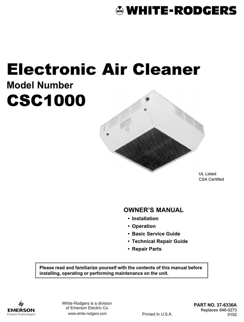
White Rodgers SSC1000 User manual

OO
OO
OWNER’S MANUWNER’S MANU
WNER’S MANUWNER’S MANU
WNER’S MANUALAL
ALAL
AL
••
••
•InstallationInstallation
InstallationInstallation
Installation
••
••
•OperationOperation
OperationOperation
Operation
••
••
•Basic Service GuideBasic Service Guide
Basic Service GuideBasic Service Guide
Basic Service Guide
••
••
•Technical Repair GuideTechnical Repair Guide
Technical Repair GuideTechnical Repair Guide
Technical Repair Guide
••
••
•Repair PartsRepair Parts
Repair PartsRepair Parts
Repair Parts
PART NO. 37-6359APART NO. 37-6359A
PART NO. 37-6359A
Replaces 846-0291C
0146
Electronic Air Cleaner
Model NumberModel Number
Model Number
SSC1000
Please read and familiarize yourself with the contents of this manual beforePlease read and familiarize yourself with the contents of this manual before
Please read and familiarize yourself with the contents of this manual before
installing, operating or performing maintenance on the unit.installing, operating or performing maintenance on the unit.
installing, operating or performing maintenance on the unit.
UL Listed
CSA Certified
White-Rodgers is a division
of Emerson Electric Co.
www.white-rodgers.com

2
Please read instructions before installing and using the Elec-
tronic Air Cleaner. This will help you obtain the full benefit from
the Electronic Air Cleaner you have selected.
SSC1000 Self Contained Drop In Electronic Air CleanerSSC1000 Self Contained Drop In Electronic Air Cleaner
SSC1000 Self Contained Drop In Electronic Air Cleaner
ModelModel
ModelModel
Model: SSC1000
VoltageVoltage
VoltageVoltage
Voltage: 120 VAC, 60 Hz.
Amps HI-speedAmps HI-speed
Amps HI-speed: 2.5 A.
Watts HI-speedWatts HI-speed
Watts HI-speed: 240
WeightWeight
WeightWeight
Weight: 50 lbs.
Shipping WeightShipping Weight
Shipping Weight: 58 lbs.
▲
!WW
WW
WARNINGARNING
ARNINGARNING
ARNING
Do not attempt installation of this unit unless you areDo not attempt installation of this unit unless you are
Do not attempt installation of this unit unless you are
familiar with the necessary tools, equipment, utilityfamiliar with the necessary tools, equipment, utility
familiar with the necessary tools, equipment, utility
connections and potential hazards.connections and potential hazards.
connections and potential hazards.
Installation should be performed only by a qualifiedInstallation should be performed only by a qualified
Installation should be performed only by a qualified
service provider.service provider.
service provider.
Failure to do so could result in reduced performanceFailure to do so could result in reduced performance
Failure to do so could result in reduced performance
of the unit, serious personal injury or death.of the unit, serious personal injury or death.
of the unit, serious personal injury or death.
▲
!WW
WW
WARNINGARNING
ARNINGARNING
ARNING
Installation of this unit must comply with local electricInstallation of this unit must comply with local electric
Installation of this unit must comply with local electric
codes or other applicable codes.codes or other applicable codes.
codes or other applicable codes.
Review and understand local codes prior toReview and understand local codes prior to
Review and understand local codes prior to
installation.installation.
installation.
Do not use this apparatusDo not use this apparatus
Do not use this apparatus in an explosive atmosphere.in an explosive atmosphere.
in an explosive atmosphere.in an explosive atmosphere.
in an explosive atmosphere.
Failure to do so could result in serious personal injuryFailure to do so could result in serious personal injury
Failure to do so could result in serious personal injury
or death.or death.
or death.or death.
or death.
1. Read the Owners Manual and the Rules for Safe
Operation carefully. Failure to follow these rules and
instructions could cause a malfunction of filter or
unsatisfactory service.
2. Follow a regular service and maintenance schedule
for efficient operation.
Fan SpeedFan Speed
Fan SpeedFan Speed
Fan Speed: Variable 200 to 1000 CFM
DimensionsDimensions
Dimensions: 233/4”H x 233/4”W x 113/4”D
EfficiencyEfficiency
Efficiency: Efficiency varies with fan speed approximately 90%
at low speed and 65% at hi speed.
Installation EfficiencyInstallation Efficiency
Installation Efficiency
NOTENOTE
NOTENOTE
NOTE:Unit must run for one full hour after installation.
This will allow the collecting cells to reach
peak efficiency.
SpecificationsSpecifications
Specifications
Table of ContentsTable of Contents
Table of Contents
Basic Tools RequiredBasic Tools Required
Basic Tools Required
Basic Tools Required . . . . . . . . . . . . . . . . . . 2
Specifications . . . . . . . . . . . . . . . . . . . . . . . . 2
How the Air Cleaner Works . . . . . . . . . . . . 2,3
Rules for Safe Installation and Operation . . 3
Installation . . . . . . . . . . . . . . . . . . . . . . . . . . 3
Operation & Maintenance . . . . . . . . . . . . . . 4
Troubleshooting Guide. . . . . . . . . . . . . . . . . 5
Replacement Parts Listing . . . . . . . . . . . . . . 7
Electronic Air Cleaner Wash Reminder . . . . 8
Screwdriver, Rule or Tape Measure, Drill
HOHO
HOHO
HOWW
WW
W THETHE
THETHE
THE AIR CLEANERAIR CLEANER
AIR CLEANERAIR CLEANER
AIR CLEANER WW
WW
WORKSORKS
ORKSORKS
ORKS
The enclosed fan circulates the air up through the bottom of the
electronic air cleaner and out through the four outlet grilles. The
ionizing section of the collecting cell contains many fine ionizing
wires that charge the incoming airborne particles. The charged
particles move into the collecting plate area and are trapped to the
plates (like a magnet attracts and collects iron filings).
The cleaned air is then drawn through a charcoal filter to assist in
removal of unpleasant odors. The cleaned and purified air is
discharged to recirculate through your building.
White Dust (Lint)White Dust (Lint)
White Dust (Lint)
An Electronic Air Cleaner is designed to collect two major types of
contaminants: ➀ Irritants (Pollens, Spores, Molds, Bacteria, etc.)
and ➁Black Soiling Contaminants (Dirt and Smoke particles).
The residue on the collecting plates of an electronic air cleaner is
black, indicating it is removing dirt from the air stream. After
installing an air cleaner you may notice white dust (typically, long
linty particles or fibers – from carpets, cotton materials or drapery
fabrics). This material is not collected by the air cleaner because it
does not contain the irritants or soiling contaminants listed above or
settles out of the air before reaching the air cleaner. The presence of
white dust does not indicate an air cleaner requires service.
Carbon (Charcoal) FiltersCarbon (Charcoal) Filters
Carbon (Charcoal) Filters
Odors are gas molecules, not particles. They cannot be removed by
an Electronic Air Cleaner or by any other filtration media designed to
remove airborne particles. However, some gases can be absorbed
by an activated carbon filter or diluted with fresh outdoor air. When
odors are present, the addition of charcoal filters will neutralize
odors, such as cooking odors, pet odors, cigar and cigarette odors,
ozone, etc. Optional charcoal filters are available for your Air
Cleaner. Refer to the parts list for the charcoal filter part number for
your Air Cleaner. Charcoal filters require replacement. They cannot
be washed. While there is no rule of thumb for how often they should
be changed, you can use your best judgement based on the odors
you perceive in your environment.
Shut off power at fuse panel beforeShut off power at fuse panel before
Shut off power at fuse panel before
servicing. Failure to do so could resultservicing. Failure to do so could result
servicing. Failure to do so could result
in serious personal injury or death.in serious personal injury or death.
in serious personal injury or death.
ELECTROCUTION HAZARDELECTROCUTION HAZARD
ELECTROCUTION HAZARD
▲
!WW
WW
WARNINGARNING
ARNINGARNING
ARNING
▲
!CACA
CACA
CAUTIONUTION
UTIONUTION
UTION
CABINET AND CELLS MAY CONTAINCABINET AND CELLS MAY CONTAIN
CABINET AND CELLS MAY CONTAIN
SHARP EDGES.SHARP EDGES.
SHARP EDGES.
Use care when servicing unit or handl-Use care when servicing unit or handl-
Use care when servicing unit or handl-
ing cells. Failure to do so could result ining cells. Failure to do so could result in
ing cells. Failure to do so could result in
minor personal injury.minor personal injury.
minor personal injury.
3
INSTINST
INSTINST
INSTALLAALLA
ALLAALLA
ALLATIONTION
TIONTION
TION
RULES FOR SAFE INSTALLATIONRULES FOR SAFE INSTALLATION
RULES FOR SAFE INSTALLATION
AND OPERATIONAND OPERATION
AND OPERATION
1. Read the Owners Manual and the Rules for Safe
Operation carefully. Failure to follow these rules and
instructions could cause a malfunction of filter or
unsatisfactory service.
2. Follow a regular service and maintenance schedule for
efficient operation.
PLACEMENTPLACEMENT
PLACEMENTPLACEMENT
PLACEMENT
The installer must be qualified to make approved electrical
connections and a safe ceiling installation with attention to the
best placement as shown in the following drawings.
The electronic air cleaner should be mounted in the center of the
room. Air is drawn through the bottom grille and discharged
through the four side grilles. Divide larger rooms into sections
and use a unit in each section (Fig. 2).
Check existing air circulation in the room. The air cleaner should
be installed so that it aids the circulation already established.
When air flow patterns are not immediately apparent, observe
the smoke from a cigarette in various locations within the room.
Do not locate the air cleaner near a heating or air conditioning
intake or exhaust vent if it interferes with the air flow discharge
and return air to the heating or air conditioning unit.
CEILING MOUNTCEILING MOUNT
CEILING MOUNT
The air cleaner is mounted by suspending it from the building
structure above the suspended ceiling. The mounting holes are
spaced 21”and 153/4”between centers (Fig. 3).
COLLECTING
PLATES
CLEAN
AIR
OUT
CLEAN
AIR
OUT
IONIZING SECTION
IONIZING WIRES GIVE DIRT
PARTICLES A POSITIVE CHARGE
CHARCOAL FILTER
REDUCES ODOR
COLLECTING SECTION
COLLECTOR PLATES ATTRACT
AND HOLD DIRT PARTICLES
LIKE A MAGNET
DIRTY
AIR IN
3838
34
34
34
11
23
21
4
4
15
23
Mounting DetailMounting Detail
Mounting Detail
Select a mounting location where the structure above is strong
enough to support the weight of approximately 50 lbs (Fig.4 &
5).
CAUTION: Do not allow the unit to be supported by theCAUTION: Do not allow the unit to be supported by the
CAUTION: Do not allow the unit to be supported by the
ceiling tile grid suspension.ceiling tile grid suspension.
ceiling tile grid suspension.
3/8" DIA. STEEL
THREADED ROD COVER
WELD NUT CEILING GRID
(DO NOT USE
FOR SUPPORT)
CEILING GRID
(DO NOT USE
FOR SUPPORT)
2X4
ROOF SUPPORT JOIST NUT & WASHER TOP AND BOTTOM
FIGFIG
FIGFIG
FIG..
..
.1 Illustr1 Illustr
1 Illustr1 Illustr
1 Illustraa
aa
ation oftion of
tion oftion of
tion of
Air Cleaning PrAir Cleaning Pr
Air Cleaning Processocess
ocessocess
ocess
FIGFIG
FIGFIG
FIG..
..
.2 Mount the unit on the ceiling a2 Mount the unit on the ceiling a
2 Mount the unit on the ceiling a2 Mount the unit on the ceiling a
2 Mount the unit on the ceiling at the centert the center
t the centert the center
t the center
ofof
ofof
of arar
arar
area to be cea to be c
ea to be cea to be c
ea to be cleaned.leaned.
leaned.leaned.
leaned.
FIGFIG
FIGFIG
FIG..
..
.33
33
3 AA
AA
Apprppr
pprppr
pproo
oo
oximaxima
ximaxima
ximate Installate Installa
te Installate Installa
te Installation Dimensions in Inction Dimensions in Inc
tion Dimensions in Inction Dimensions in Inc
tion Dimensions in Incheshes
heshes
hes
FIGFIG
FIGFIG
FIG..
..
.44
44
4
FIGFIG
FIGFIG
FIG..
..
.55
55
5

4
OPERAOPERA
OPERAOPERA
OPERATION/MAINTENTION/MAINTEN
TION/MAINTENTION/MAINTEN
TION/MAINTENANCEANCE
ANCEANCE
ANCE
WIRING INSTRUCTIONSWIRING INSTRUCTIONS
WIRING INSTRUCTIONS
Standard electrical wiring of 120 volts, 60 Hz, 15 Amp circuit is
adequate. Local residential and commercial wiring codes shall
apply. Flexible conduit should be used (Fig. 6).
OPERATIONOPERATION
OPERATIONOPERATION
OPERATION
WASHINGWASHING
WASHINGWASHING
WASHING
For maximum efficiency, your air cleaner cell must be
inspected periodically and cleaned when necessary. The
cleaning frequency will vary, depending on the amount of
airborne contaminants. A smoky environment significantly
increases the required cleaning frequency. When cleaning is
required the following procedure should be used:
CLEANING THE CELLCLEANING THE CELL
CLEANING THE CELL
1. Turn the control switch to “OFF”.
2. Turn two thumb screws to release grille and swing down.
Push aside latches and swing cell down to remove. De-
press spring latch and remove charcoal filter. Close grille
to avoid safety hazard.
NOTE: Do not wash the charcoal filterNOTE: Do not wash the charcoal filter
NOTE: Do not wash the charcoal filter.
3. Soak cell for 20 to 30 minutes in a solution of warm water
and liquid laundry detergent or electronic air cleaner
cleaning solution. Do not use dishwashing detergent
because it may leave a residue on the plates, decreasing
the air cleaning efficiency of the unit.
NOTENOTE
NOTENOTE
NOTE: Ionizing wires may become coated, causing loss
of cleaning ability by the collecting cell. Using a damp
cloth, wipe each ionizing wire, exercising care not to
damage them.
4. Remove the cell from solution and rinse thoroughly with
clean water.
5. Allow cell to drip dry for a minimum of 2 hoursminimum of 2 hours
minimum of 2 hoursminimum of 2 hours
minimum of 2 hours. Cell
may be tipped at a slight angle to expedite the drip-dry
process.
6. Open grille and replace charcoal filter.
7. Hook the slotted tabs of the cell on hooks in the cabinet
and swing the cell up into place. Push latches back in
place to hold the cell.
8. Close the grille and securely fasten with two thumb
screws.
9. Turn the control switch to desired fan speed.
A moderate amount of arcing or “snapping” may occur at
this time, which will indicate that the cell is still damp. If
the noise is objectionable, turn the control switch to “OFF”
and allow additional time for the cell to dry.
3. The Operating Light should be ON whenever the fan is
running. An occasional flicker of the light accompanied
by harmless sparking or snapping noise may occur. This
is caused by the plates trapping large particles. If arcing
is continuous, the cells should be washed or checked
for service problems.
1. With the 120 VAC power turned on, adjust the HIGH/
LOW/OFF knob to the position desired.
2. When the fan is running, the air cleaner will be operating.
An arcing or “snapping” sound may be heard occasion-
ally, however the unit is operating properly.
▲
!CACA
CACA
CAUTIONUTION
UTIONUTION
UTION
CABINET AND CELLS MAY CONTAINCABINET AND CELLS MAY CONTAIN
CABINET AND CELLS MAY CONTAIN
SHARP EDGES.SHARP EDGES.
SHARP EDGES.
Use care when servicing unit or handl-Use care when servicing unit or handl-
Use care when servicing unit or handl-
ing cells. Failure to do so could result ining cells. Failure to do so could result in
ing cells. Failure to do so could result in
minor personal injury.minor personal injury.
minor personal injury.
TOP OF
UNIT
GREEN
WHITE
BLACK
FIELD GROUND
FIELD NEUTRAL
FIELD HOT
BOX (INTERNAL)
FIGFIG
FIGFIG
FIG..
..
.66
66
6

5
▲
!WW
WW
WARNINGARNING
ARNINGARNING
ARNING
Do not attempt repair of this unit unless you areDo not attempt repair of this unit unless you are
Do not attempt repair of this unit unless you are
familiar with the necessary tools, equipment, utilityfamiliar with the necessary tools, equipment, utility
familiar with the necessary tools, equipment, utility
connections and potential hazards.connections and potential hazards.
connections and potential hazards.
Repair should be performed only by a qualifiedRepair should be performed only by a qualified
Repair should be performed only by a qualified
service provider.service provider.
service provider.
Failure to do so could result in reduced performanceFailure to do so could result in reduced performance
Failure to do so could result in reduced performance
of the unit, serious personal injury or death.of the unit, serious personal injury or death.
of the unit, serious personal injury or death.
TECHNICAL REPTECHNICAL REP
TECHNICAL REPAIR GUIDEAIR GUIDE
AIR GUIDEAIR GUIDE
AIR GUIDE
This guide contains service checks to assist service personnel
in locating and correcting any malfunction that might occur to
render the air cleaner ineffective or inoperative. The air cleaner
has been designed with replaceable components, such as the
high-voltage power supply and air flow switch. This allows the
serviceman to replace a faulty component rather than attempt
repairs of such components in the field.
SERSER
SERSER
SERVICE INDICAVICE INDICA
VICE INDICAVICE INDICA
VICE INDICATIONTION
TIONTION
TION SERSER
SERSER
SERVICE CHECKSVICE CHECKS
VICE CHECKSVICE CHECKS
VICE CHECKS
Control switch “ON” Unit functioning NorUnit functioning Nor
Unit functioning NorUnit functioning Nor
Unit functioning Normallmall
mallmall
mallyy
yy
y..
..
.
Fan operating
Operating Light ON
Control switch “ON” 1.1.
1.1.
1. PP
PP
Poo
oo
oww
ww
wer is not being supplied to air cer is not being supplied to air c
er is not being supplied to air cer is not being supplied to air c
er is not being supplied to air cleanerleaner
leanerleaner
leaner
..
..
.
Fan not operating A. Check fuse or circuit breaker.
Operating Light OFF B. Make sure that grille is closed and safety switch is pushed in.
Excessive arcing during 1.1.
1.1.
1. Collecting cell dirCollecting cell dir
Collecting cell dirCollecting cell dir
Collecting cell dirtyty
tyty
ty
..
..
.
normal operation – A. Clean cell thoroughly as instructed in this manual.
Operating Light may blink 2.2.
2.2.
2. WW
WW
Wet collecting cell.et collecting cell.
et collecting cell.et collecting cell.
et collecting cell.
A. Allow cell to dry after cleaning before applying power.
NONO
NONO
NOTETE
TETE
TE: Occasional arcing 3.3.
3.3.
3. ExEx
ExEx
Excessicessi
cessicessi
cessivv
vv
ve airbore airbor
e airbore airbor
e airborne mane ma
ne mane ma
ne material.terial.
terial.terial.
terial.
or “snapping” is considered A. Additional air cleaner(s) may be required in extreme environments.
normal. B. Additional clean make-up air may be required.
4.4.
4.4.
4. DamaDama
DamaDama
Damagg
gg
ged or shored or shor
ed or shored or shor
ed or shorted collecting cell.ted collecting cell.
ted collecting cell.ted collecting cell.
ted collecting cell.
A. Inspect cell for bent plates. Straighten plates as necessary.
B. Check for foreign objects shorting across cell plates or ionizing section.
C. Inspect cell for loose or broken ionizing wire(s). Replace as needed.
D. Inspect cell for cracked or broken insulator(s), around cell perimeter.
Replace collecting cell if condition persists.
5.5.
5.5.
5. DamaDama
DamaDama
Damagg
gg
ged ced c
ed ced c
ed charhar
harhar
harcoal filtercoal filter
coal filtercoal filter
coal filter
..
..
.
A. Remove charcoal filter. If arcing/snapping stops, the filter may be
breaking down and require disposal or replacement.
Control switch “ON” 1.1.
1.1.
1. DamaDama
DamaDama
Damagg
gg
ged or shored or shor
ed or shored or shor
ed or shorted collecting cell.ted collecting cell.
ted collecting cell.ted collecting cell.
ted collecting cell.
Fan operating A. Remove collecting cell. Close exhaust grille so safety switch is pushed
Operating Light OFF in. If Operating light comes ON with cell removed, check cell as
described above. If light does not come ON, proceed to next step.
2.2.
2.2.
2. PP
PP
Poo
oo
oww
ww
wer Suppler Suppl
er Suppler Suppl
er Supplyy
yy
y..
..
.
A. Remove collecting cell. With safety switch pushed in, 120 VAC should
be present at terminals marked “LINE” on power supply. If voltage is
below 6100 VDC at red high voltage terminal on power supply, replace
power supply. If voltage is correct, replace indicator light.
NONO
NONO
NOTETE
TETE
TE: Unit may require up to one hour of operation to reach indicated
voltage when first installed or when replacing cell.

6
OZONE REDUCTIONOZONE REDUCTION
OZONE REDUCTION
All electronic air cleaners typically produce a small amount of
ozone that is within established limits. Some customers may
notice an odor especially at high altitudes or low air flow rates.
This power supply has a “hairpin” shaped jumper wire labeled
W1 that can be cut and separated in case of such complaints.
This will cause the power supply to limit the maximum operating
power to a lower level.
LINE
WHT/BRN BLK
W1
E3 E2
Cut and separate
Ozone Reduction
Jumper
SSC1000SSC1000
SSC1000SSC1000
SSC1000
WIRING DIAWIRING DIA
WIRING DIAGRAMGRAM
GRAMGRAM
GRAM

7
ITEM NOITEM NO
ITEM NOITEM NO
ITEM NO..
..
.DESCRIPTIONDESCRIPTION
DESCRIPTIONDESCRIPTION
DESCRIPTION SSC1000SSC1000
SSC1000SSC1000
SSC1000
1 Power Supply 5088A-101
2 Knob F839-0019
3 Switch, Variable Speed F876-0203
4 Light F844-0131
5 Switch, Safety F876-0199
6 Charcoal Filter F825-0494
7 Collecting Cell F811-0421
8 Ionizing Wire F843-0484
9 Fan Motor N/A
10 Fan Blade N/A
††
††
† Manual 37-6359
REPLAREPLA
REPLAREPLA
REPLACEMENTCEMENT
CEMENTCEMENT
CEMENT
PP
PP
PARAR
ARAR
ARTS DIATS DIA
TS DIATS DIA
TS DIAGRAMGRAM
GRAMGRAM
GRAM
FOR SSC1000FOR SSC1000
FOR SSC1000
††
††
† Not Shown

NOTICETO CONSUMERS
White-Rodgers
Electronic Air Cleaner
Dear Consumer;
White-Rodgers would like to thank you for purchasing a White-Rodgers Electronic Air Cleaner or
product containing a White-Rodgers Electronic Air Cleaner. Although White-Rodgers does not extend
a warranty directly to consumers, White-Rodgers does extend a warranty to Wholesalers and Original
Equipment Manufacturers who use White-Rodgers Products. To obtain more information about how
your Wholesaler or Original Equipment Manufacturer’s warranty may benefit you, please contact your
Wholesaler or Original Equipment Manufacturer.
Sincerely,
White-Rodgers
Year JAN FEB MAR APR MAY JUN JUL AUG SEP OCT NOV DEC
20___
20___
20___
20___
20___
20___
20___
20___
20___
20___
20___
20___
WASH REMINDER SCHEDULEWASH REMINDER SCHEDULE
WASH REMINDER SCHEDULE
A regular washing schedule is necessary to ensure proper
efficiency. A thorough washing once every month will be ad-
equate for most installations. More or Less
frequent washing may be necessary on some installations
where there is new carpeting, plaster dust or excessive cigarette
smoke, etc. (See page 4 for maintenance and instructions on
how to clean a cell.)
The Emerson logo is a
trademark and service mark
of Emerson Electric Co.
www.white-rodgers.com

MANUEL DU PROPRIÉTAIRE
•Installation
•Utilisation
•Entretien
•Guide de dépannage
•Pièces de rechange
NoDE PIÈCE 37-6359A
Remplace 846-0291C
0146
Épurateur d’airÉpurateur d’air
Épurateur d’air
électroniqueélectronique
électronique
Numéro de modèle
SSC1000
Prière de lire attentivement le manuel avant d’installer l’article, de l’utiliser ou d’en faire
l’entretien.
Homologation UL
Certification CSA
White-Rodgers est une division
d’Emerson Electric Co.
www.white-rodgers.com

2
Prière de lire les directives avant d’installer et d’utiliser l’épurateur
d’air électronique afin de profiter pleinement des avantages de cet
appareil.
Épurateur d’air électronique SSC1000 autonome à suspendre
Modèle : SSC1000
Tension : 120 V CA, 60 Hz
Courant absorbé à vitesse élevée (HI) : 2,5 ampères
Puissance absorbée à vitesse élevée (HI) : 240 watts
Poids : 23 kg (50 lb)
Poids d’expédition : 26 kg (58 lb)
Débit du ventilateur : Variable de 200 à 1000 pi3/min
Nepastenterd’installerl’appareil avantdes’être familiarisé
complètement avec les exigences en matière d’outils,
d’équipements et de raccordements aux services publics
ainsi qu’avec les dangers qui sont présents.
Pour installer l’appareil, il est recommandé de faire appel
à un technicien agréé.
Sicesinstructionsn’étaientpassuivies, les performances
de l’appareil pourraient être réduites et des blessures
graves, voire un décès, pourraient survenir.
L’installation doit respecter le code de l’électricité et tout
autre code en vigueur.
Avant de procéder à l’installation, prendre connaissance
des codes en vigueur.
Ne pas utiliser cet appareil en présence de gaz explosifs.
Si ces instructions ne sont pas respectées, des blessures
graves, voire un décès, peuvent survenir.
Caractéristiques techniques
Table des matières
Outils de base requis ....................................................... 2
Caractéristiques techniques ............................................. 2
Fonctionnement du filtre à air ........................................ 2,3
Installation ........................................................................ 3
Directives d’installation et d’exploitation sécuritaires ....... 3
Utilisation et entretien ....................................................... 4
Guide de dépannage ........................................................ 5
Liste de pièces de rechange ............................................ 7
Fiche de rappel de lavage ................................................ 8
Outils de base requis
Tournevis, règle ou ruban à mesurer, perceuse
FONCTIONNEMENT DU FILTRE À AIR
Le ventilateur tire l’air par le fond de l’épurateur et l’expulse par les
quatre grilles. L’étage d’ionisation de la cellule collectrice comporte
plusieurs minces fils ionisants qui donnent une charge électrique
aux particules qui pénètrent dans l’appareil. Les particules ionisées
traversent ensuite le collecteur où elles sont captées par les plaques
qui le composent (comme la limaille de fer est attirée par un aimant).
L’air propre passe alors à travers un filtre à charbon qui aide à
éliminer les odeurs désagréables. Enfin, l’air nettoyé et purifié est
expulsé dans la pièce.
Poussière blanche (peluches)
L’épurateur est conçu pour capter principalement deux sortes de
contaminants:➀ Les irritants (pollen, spores, moisissure, bactéries,
etc.); et ➁les contaminants salissants (particules de saleté et de
fumée).
Les résidus qui s’accumulent sur les plaques d’un épurateur
électronique sont noirs; toute cette saleté est retirée de l’air ambiant.
Après l’installation du filtre à air, il est possible que vous remarquiez
une poussière blanche (en règle générale, de longues particules de
peluches ou de fibres, provenant de moquettes, de coton et de
rideaux). Ces substances ne sont pas captées par l’épurateur, soit
parce qu’elles ne contiennent pas les irritants et les contaminants
mentionnés plus haut, soit parce qu’elles se sont déposées avant
d’avoir pu atteindre l’épurateur. La présence de poussière blanche
ne signifie pas qu’il est temps de faire réviser l’épurateur.
Filtre à charbon actif
Les odeurs sont causées par des molécules de gaz et non par des
particules. Ainsi, il est impossible de les éliminer à l’aide d’un
épurateur d’air électronique ou de tout autre milieu filtrant conçu
pour capter les particules en suspension dans l’air. Or, il est possible
d’adsorber certains gaz à l’aide d’un filtre à charbon actif ou de les
diluer par un apport d’air frais en provenance de l’extérieur. Si des
odeurssontprésentes,commelesodeurs de cuisson, d’animaux de
compagnie, de cigare ou de cigarette, etc., l’ajout d’un filtre à
charbon actif peut les neutraliser. On peut se procurer des filtres à
charbon facultatifs pour usage avec l’épurateur d’air électronique.
Pour en connaître le numéro de pièce, se reporter à la liste de pièces
correspondant à l’épurateur installé. Les filtres à charbon doivent
être remplacés régulièrement; ils ne peuvent être lavés. Il n’existe
aucune règle générale quant à la fréquence de leur changement;
nousrecommandonssimplementdefaire appel à votre jugement en
fonction des odeurs perçues dans le foyer.
RISQUE D’ÉLECTROCUTION
Avant de réviser l’appareil, couper le
courantaupanneaudedistribution.Sices
instructions ne sont pas respectées, des
blessuresgraves, voire un décès, peuvent
survenir.
▲
!MISE EN GARDE
▲
!ATTENTION
LE BOÎTIER ET LES CELLULES PEUVENT
AVOIR DES BORDS COUPANTS.
Manipuler soigneusement les cellules lors
de la révision ou de l’installation. Si ces
instructions ne sont pas suivies, des
blessures légères peuvent survenir.
1. Lire attentivement le manuel du propriétaire ainsi que les
directivesd’exploitationsécuritaire. Si ces directives ne sont pas
suivies, l’appareil risque de fonctionner incorrectement ou pas
du tout.
2. Effectuer régulièrement les révisions et l’entretien afin d’assurer
un fonctionnement efficace de l’appareil.
▲
!MISE EN GARDE
▲
!MISE EN GARDE
Dimensions (hauteur x largeur x profondeur) :
60 x 60 x 30 cm (233⁄4x 233⁄4x 113⁄4po)
Rendement : Le rendement est fonction de la vitesse du
ventilateur, soit d’environ 90 % à basse vitesse et
de 65 % à vitesse élevée.
Rendement après l’installation
REMARQUE : Il estessentielde fairefonctionnerl’appareil pendant
une heure complète immédiatement après son
installation. Cela permet d’assurer le rendement
optimal des cellules.

3
INSTALLATION
DIRECTIVES D’INSTALLATION ET
D’EXPLOITATION SÉCURITAIRES
1. Lire attentivement le manuel du propriétaire ainsi que les
directivesd’exploitationsécuritaire. Si ces directives ne sont pas
suivies, l’appareil risque de fonctionner incorrectement ou pas
du tout.
2. Effectuer régulièrement les révisions et l’entretien afin d’assurer
un fonctionnement efficace de l’appareil.
CHOIX DE L’EMPLACEMENT
L’installateur doit posséder les compétences nécessaires pour
effectuer le raccordement électrique conforme de l’appareil et son
installation sécuritaire au plafond en tenant compte des contraintes
discutées plus loin.
L’épurateur d’air électronique s’installe de préférence au centre de
la pièce. Il aspire l’air par sa grille inférieure et l’expulse par les
quatre grilles latérales. Subdiviser les grandes pièces en sections
et placer un appareil au centre de chacune (figure 2).
Tenir compte de la circulation d’air actuelle dans la pièce. Installer
l’épurateur de manière qu’il participe à la circulation déjà établie. Si
aucun courant n’est apparent, observer la fumée d’une cigarette à
plusieurs endroits dans la pièce. Ne pas situer l’épurateur près d’un
registred’entréeou de sortie d’air du chauffage ou delaclimatisation
s’il nuit à la circulation nécessaire au bon fonctionnement de ces
appareils.
INSTALLATION AU PLAFOND
L’épurateurestsuspenduàla structure du bâtiment, au-dessus d’un
plafond suspendu. Les trous de montage ont un espacement de
53 cm (21 po) et de 40 cm (153⁄4po) entraxe (figure 3).
PLAQUES
COLLECTRICES
SORTIE
DʼAIR
PROPRE
SORTIE
DʼAIR
PROPRE
ÉTAGE DʼIONISATION :
LES FILS IONISANTS DONNENT
UNE CHARGE POSITIVE AUX
PARTICULES DE SALETÉ
FILTRE À CHARBON
QUI ATTÉNUE LES ODEURS
ÉTAGE COLLECTEUR :
COMME UN AIMANT, LES PLAQUES
COLLECTRICES ATTIRENT ET RETIENNENT
LES PARTICULES DE SALETÉ
ENTRÉE DʼAIR
POUSSIÉREUX
3838
34
34
34
11
23
21
4
4
15
23
Détail de montage
Choisir pour monter l’appareil un endroit où la structure qui se trouve
au-dessus est suffisamment résistante pour supporter un poids
d’environ 23 kg (50 lb) (figures 4 et 5).
ATTENTION : Ne pas faire en sorte que l’appareil soit supporté
par les rails de montage du plafond suspendu.
TIGE FILET
É
E
EN ACIER DE
3/8" DIAM. BOÎTIER
ÉCROU À
SOUDER
RAILS DE
PLAFOND SUSPENDU
(NE PAS UTILISER
COMME SUPPORT)
RAILS DE
PLAFOND SUSPENDU
(NE PAS UTILISER
COMME SUPPORT)
2X4
SOLIVES DU TOIT
É
CROU ET RONDELLE
DE PART ET DʼAUTRE
Figure 1. Le processus d’épuration
Figure 2. Appareil installé au plafond
au centre de la zone à nettoyer
Figure 3. Dimensions d’installation approximatives
en pouces
Figure 4.
Figure 5.

4
UTILISATION ET ENTRETIEN
MODE D’EMPLOI
1. Alimenter l’appareil en courant de 120 V CA et régler le bouton
HIGH/LOW/OFF(vitesse élevée/bassevitesse/arrêt) àlaposition
désirée.
2. Lorsque le ventilateur fonctionne, l’épurateur est également en
marche. Un claquement, qui est émis lorsqu’il y a formation d’un
arc électrique, peut se faire entendre à l’occasion lorsque
l’appareil fonctionne normalement.
CÂBLAGE
Un circuit ordinaire de 120 volts, 60 hertz et 15 ampères suffit. Tenir
compte du code de l’électricité en vigueur pour les bâtiments
résidentiels et commerciaux. Utiliser un conduit flexible (figure 6).
LAVAGE
Pour fonctionner au rendement maximal, la cellule de l’épurateur
nécessiteune inspection périodiqueet un lavagelorsquenécessaire.
La fréquence du nettoyage varie en fonction de la quantité de
contaminants en suspension dans l’air. Dans un environnement où
il y a beaucoup de fumée, la nécessité de nettoyer est nettement
plus fréquente. Lorsque le nettoyage est requis, procéder de la
façon suivante :
NETTOYAGE DE LA CELLULE
1. Régler le commutateur à OFF (arrêt).
2. Dévisser les boutons de la grille et ouvrir celle-ci. Repousser les
taquets, faire pivoter la cellule vers le bas et la retirer. Enfoncer
l’attache à ressort et retirer le filtre à charbon. Refermer la grille
par mesure de sécurité.
REMARQUE : Ne pas laver le filtre à charbon.
3. Laisser tremper la cellule pendant 20 à 30 minutes dans une
solution d’eau tiède et de détergent à lessive liquide ou de
solution de nettoyage pour épurateur d’air électronique. Ne pas
utiliser de détergent à vaisselle, qui pourrait laisser un résidu sur
les plaques, nuisant ainsi au rendement de l’appareil.
REMARQUE : Il est possible que les fils ionisants soient
recouvertsde saletés, ce qui diminuelerendement du collecteur.
Essuyer les fils un à un avec un linge humide en prenant soin de
ne pas les endommager.
4. Sortir la cellule de la solution et la rincer soigneusement à l’eau
claire.
5. Laisser la cellule sécher à l’air libre pendant un minimum de
2 heures. La pencher légèrement peut accélérer le séchage.
6. Ouvrir la grille et réinstaller le filtre à charbon.
7. Accrocher les pattes fendues de la cellule sur les crochets du
boîtier et loger la cellule en la faisant pivoter. Replacer les
taquets afin qu’ils retiennent la cellule.
8. Fermer solidement la grille à l’aide des deux boutons.
9. Régler le commutateur à la vitesse de ventilateur désirée.
À ce stade, il est possible qu’il y ait beaucoup de claquement et
la formation d’arcs électriques. Cela signifie que la cellule est
encore humide. Si le bruit dérange, arrêter l’appareil et attendre
encore un peu que la cellule sèche.
▲
!ATTENTION
LE BOÎTIER ET LES CELLULES PEUVENT
AVOIR DES BORDS COUPANTS.
Manipuler soigneusement les cellules lors
de la révision ou de l’installation. Si ces
instructions n’étaient pas suivies, des
blessures légères pourraient survenir.
DESSUS DE
LʼAPPAREIL
VERT
BLANC
NOIR
MALT DE LʼINSTALLATION
NEUTRE DE LʼINSTALLATION
TENSION DE LʼINSTALLATION
BOÎTE (INTERNE)
Figure 6.
3. Le voyant de marche est habituellement allumé lorsque le
ventilateur tourne. Il peut cependant clignoter à l’occasion, en
même temps qu’un claquement se fait entendre. Cela survient
lorsque les plaques captent de grosses particules. Si le
claquement est continu, alors il est temps de laver la cellule ou
de la réviser afin d’y détecter tout problème.

5
Ne pas tenter de réparer l’appareil avant de s’être
complètementfamiliarisé avecles outils etles équipements
requis, avec les exigences en matière de raccordements
aux services publics ainsi qu’avec les dangers qui sont
présents.
Pour réparer l’appareil, il est recommandé de faire appel à
un technicien agréé.
Sicesinstructionsn’étaientpassuivies, les performances
del’article pourraient êtreréduiteset des blessuresgraves,
voire un décès, pourraient survenir.
GUIDE DE DÉPANNAGE
Le présent guide décrit les vérifications à effectuer dans le but
d’aider les techniciens à identifier et à corriger tout problème qui
pourrait rendre l’épurateur inefficace ou le mettre hors service.
L’épurateurest fabriquéavec des composantsremplaçables, comme
le module d’alimentation à haute tension et le détecteur de débit
d’air. Cela permet au réparateur de remplacer tout simplement un
composant défectueux au lieu de tenter de le réparer sur place.
▲
!MISE EN GARDE
Commutateur à ON
Ventilateur en marche
Voyant de marche allumé
L’appareil fonctionne correctement.
FONCTIONNEMENT RÉVISION
Commutateur à ON
Ventilateur arrêté
Voyant de marche éteint
Claquement excessif en
fonctionnement normal; le voyant
de marche peut clignoter
REMARQUE: Un claquement
occasionnel est normal.
1. Cellule collectrice sale.
A. Laver soigneusement la cellule de la manière indiquée dans le présent
manuel.
2. Cellule collectrice mouillée.
A. Avant de rétablir le courant après le nettoyage de la cellule collectrice,
attendre que celle-ci ait séché.
3. Quantité excessive de particules en suspension dans l’air.
A. Dans certains environnements, il peut être nécessaire d’ajouter un ou
plusieurs épurateurs.
B. Un supplément d’air d’appoint propre peut être nécessaire.
4. Cellule collectrice endommagée ou court-circuitée.
A. Inspecter la cellule à la recherche de plaque fléchies. Redresser les plaques
le cas échéant.
B. Vérifier si des corps étrangers causent un court-circuit entre les plaques ou
avec l’étage d’ionisation de la cellule.
C. Inspecter la cellule à la recherche de fils ionisants lâches ou brisés. Les
remplacer le cas échéant.
D. Inspecter le périmètre de la cellule à la recherche de fissures ou de
cassures dans l’isolant. Remplacer la cellule collectrice si la condition
persiste.
5. Filtre à charbon endommagé.
A. Retirer le filtre à charbon. Si le claquement cesse, cela signifie peut-être que
le filtre se désagrège et qu’il faut le jeter ou le remplacer.
Commutateur à ON
Ventilateur en marche
Voyant de marche éteint
1. Cellule collectrice endommagée ou court-circuitée.
A. Retirer la cellule collectrice. Refermer la grille de manière à faire en sorte
que l’interrupteur de sécurité soit enfoncé. Si le voyant de marche s’allume
sans que la cellule soit installée, vérifier celle-ci de la manière indiquée plus
haut. Si le voyant reste éteint, passer à l’étape suivante.
2. Bloc d’alimentation.
A. Retirer la cellule collectrice. Lorsque l’interrupteur de sécurité est enfoncé,
un courant de 120 V CA doit passer aux bornes LINE du bloc d’alimentation.
Si la tension est inférieure à 6100 V CC aux bornes rouges à haute tension
du bloc d’alimentation, remplacer celui-ci. Si la tension est bonne, remplacer
la lampe du voyant.
REMARQUE : Au moment de mettre en service l’appareil et après le
remplacement de la cellule, il peut s’écouler jusqu’à une heure de
fonctionnement avant que la tension indiquée soit atteinte.
1. L’épurateur n’est pas alimenté en courant électrique.
A. Vérifier le fusible ou le coupe-circuit.
B. S’assurer que la grille est fermée et que l’interrupteur de sécurité est
enfoncé.

6
RÉDUCTION DE L’OZONE
En règle générale, tous les épurateurs d’air électroniques dégagent
une petite quantité d’ozone qui est inférieure aux normes établies.
Certainsclients noteront une odeur, particulièrementà haute altitude
ou à faible débit.
Le module d’alimentation est doté d’un cavalier en forme de boucle
identifié par W1. Si des plaintes de cette nature se manifestent,
couper ce cavalier et en séparer les brins. Le module d’alimentation
limitera alors la puissance d’exploitation maximale de l’appareil à un
niveau plus faible.
LINE
WHT/BRN BLK
W1
E3 E2
Couper et séparer
le cavalier réducteur
dʼozone
SSC1000
SCHÉMA DE CÂBLAGE
Blanc
Blanc
vers
120 V CA
Blanc
Blanc
Blanc
Blanc et brun
Bloc
dʼalimentation
Bleu
Blanc et brun
Noir
Rouge
MALT
Isolant et contact
de cellule
Voyant de
marche
Bleu
Commutateur
à vitesse
variable
Noir
Noir Noir
Noir
Bleu Bleu
Noir
vers
120 V CA
Noir
Noir
Noir
Commutateur
de sécurité
Moteur de
ventilateur
MALT

7
CODE DESCRIPTION SSC1000
1Bloc d’alimentation 5088A-101
2Bouton F839-0019
3Commutateur à vitesse
variable F876-0203
4 Lampe F844-0131
5Commutateur de
sécurité F876-0199
6Filtre à charbon F825-0494
7Cellule collectrice F811-0421
8Fil ionisant F843-0484
9Moteur de ventilateur s. o.
10 Pale de ventilateur s. o.
† Manuel 37-6359
SCHÉMA DES PIÈCES DE
RECHANGE DU SSC1000
†Élément non illustré

AVIS AUX CONSOMMATEURS
Épurateur d’air électronique
White-Rodgers
Cher consommateur,
White-Rodgers tient à vous remercier d’avoir acheté un épurateur d’air électronique de marque White-Rodgers
ou un produit qui en contient un. White-Rodgers ne propose pas de garantie qui protège directement les
consommateurs. Cependant, l’entreprise garantit ses produits auprès des grossistes et des fabricants qui les
utilisent. Pour savoir comment cette garantie peut vous avantager, nous vous prions de communiquer
directement avec votre grossiste ou avec le fabricant de votre équipement.
Veuillez agréer, cher client, nos salutations distinguées.
White-Rodgers
Année JAN FÉV MAR AVR MAI JUN JUL AOÛ SEP OCT NOV DÉC
20___
20___
20___
20___
20___
20___
20___
20___
20___
20___
20___
20___
RAPPEL DE LAVAGE
Le lavage périodique est essentiel pour assurer le rendement
optimal de l’appareil. Pour la plupart des installations, un lavage à
fond mensuel est suffisant. Un lavage plus ou moins fréquent pourra
Le logo Emerson est une marque
de commerce et de service
d’Emerson Electric Co.
www.white-rodgers.com
être indiqué en présence de moquettes neuves, de poussière de
plâtre ou de fumée de cigarette excessive, etc. (Voir les instructions
de lavage à la page 4, section Lavage.)
Table of contents
Languages:
Other White Rodgers Air Cleaner manuals

White Rodgers
White Rodgers SST1600 User manual

White Rodgers
White Rodgers Electro-Air 10C27S-010 User manual

White Rodgers
White Rodgers pmnACM/ACB User manual

White Rodgers
White Rodgers SST User manual

White Rodgers
White Rodgers MCS600 User manual

White Rodgers
White Rodgers ComfortPro User manual

White Rodgers
White Rodgers CSC1000 User manual

White Rodgers
White Rodgers SST1400 User manual

White Rodgers
White Rodgers Comfort Plus ACM1000 User manual

White Rodgers
White Rodgers SST2000 User manual