Wiard Model GR-331 Envelator
© 1996-2003 Wiard Synthesizer Company – design by Bill Sequeira/Axon Hillock Voltage Controlled Envelope Generator
Wiard GR-331 Dual Envelator
Rev: 031001
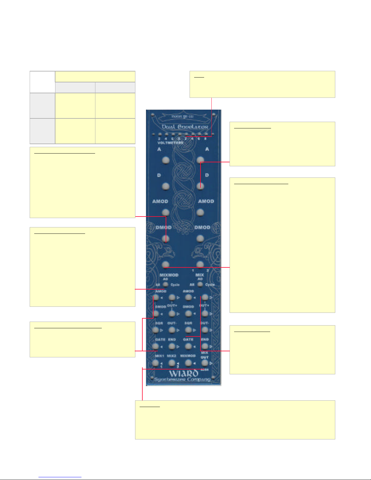
LEDs
The LED bank is split into two sections, where each 4-lamp section shows
the current output value (in volts) of its respective envelope. The LEDs
increment in 2 volt steps. When the voltage is above 8 volts, the last LED
remains on. When no LEDs are lit, the voltage is below 2 volts.
Envelope Controls
A[knob] Attack - The attack time for the envelope.
D [knob] Decay/Release - The decay and/or release
time for the envelope. If the AR/AD/Cycle switch is
set to AR, this control is the release time used when
a gate signal is removed from the GATE input jack.
If the switch is set to AD or Cycle, this control is the
decay time measured from the time that the
envelope completed the attack cycle time
Envelope Modulation Controls
AMOD [knob] - Attack Modulation Setting - Attack
Modulation allows for voltage control of the attack
time. This control allows adjustment of the amount
of modulation to the attack time as input into the
AMOD input jack. Positive voltages decrease
segment time.
DMOD [knob]- Decay Modulation Setting - Decay
Modulation allows for the voltage control of the
decay (or release) time. This control allows
adjustment of the amount of modulation to the
decay/release time as input into the DMOD input
jack. Positive voltages decrease segment time.
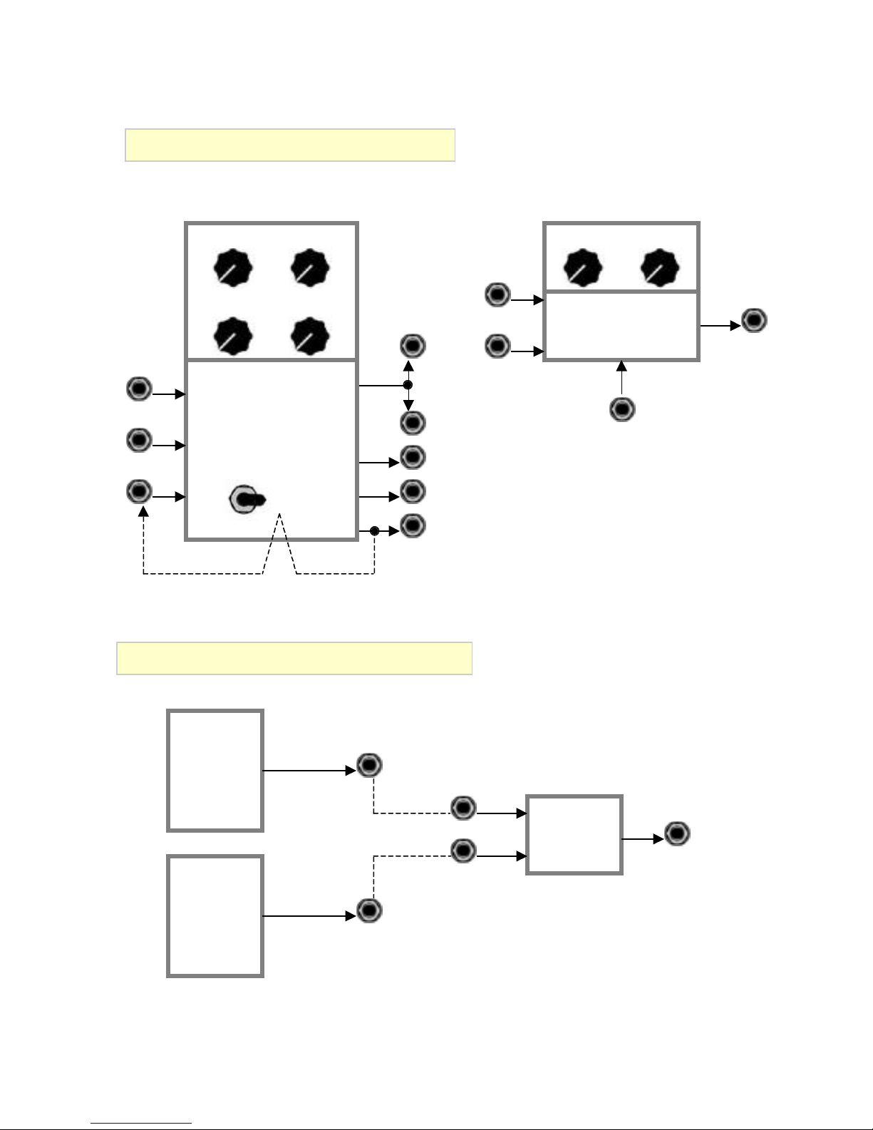
Mixer/Cross-fade Controls
MIXMOD [knob] - The Mixture Modulation control is
an attenuator for the MIXMOD voltage input. This
provides for the voltage control of mixed envelope
(or other signal) cross-fading. When used as a
voltage controlled ADSR, this acts as the sustain
voltage control.
MIX [knob] - The Mix control will cross-fade from
the MIX1 and MIX2 input jacks, sending the output
to the MIXOUT output jack. When the Mix control is
used for the two envelopes in the Envelator, this
control will allow you to create an ADSR:
•Use Envelope 1 in AD mode, Envelope 2 in AR
mode.
•The positive outputs of the two envelopes are
normalized to the MIX1 and MIX2 inputs (as
indicated by the 1 and 2 below the in arrows).
•Set the MIX control to the 12 noon position
(evenly mixing the two envelopes).
•Both attack stages will affect the attack stage,
then the decay stage of Envelope 1 will drop
the voltage to the sustaining level (as
controlled by the MIX control). When the
gate is released, the release stage of
Envelope 2 will provide a release stage for the
overall envelope shape.
•The MIXMOD knob behaves like a normal
“sustain” level control, providing voltage
control of the sustain level.
Envelope Mode Selection
AR/AD/Cycle [switch] - This switch determines
the function of the envelopes. When set to AR, the
envelope will act as an AR envelope, maintaining
full level until GATE [in] goes “low”. In AD mode,
the envelope acts as an AD envelope, and will begin
decay as soon as the attack stage is complete. The
END output “pulses” when the decay stage is
complete, in Cycle mode, this pulse is fed back to
the envelope input, and will force the envelope to
re-trigger (oscillate). In this mode, the Envelator
output functions as a shaped triangle waveform
LFO. When in Cycle mode, the SQR output acts as
a square wave LFO with the pulse width determined
by the settings of the Aand Dcontrols. This output
can also be used to clock the Wiard Sequantizer.
Each envelope is individually switched.
Envelope Trigger and Modulation
AMOD [in] - Voltage control input for Attack rate
modulation.
DMOD [in] - Voltage control input for
Decay/Release rate modulation.
GATE [in] - The gate or trigger input used to start
Envelope Outputs
END [out] - When the Decay (or Release) phase of
the envelope is complete, a “pulse” is output from
this jack.
OUT+ [out] - The positive envelope output.
OUT- [out] - The negative envelope output.
SQR [out] - The output of the trigger latch, where
the signal goes high during the attack phase and
goes low for the decay portion of the envelope.
Mixer I/O
MIX1 [in] - Input 1 for the Mix function. This input is normalized to the OUT+ output of Envelator 1.
MIX2 [in] - Input 2 for the Mix function. This input is normalized to the OUT+ output of Envelator 2.
MIXMOD [in] - An input signal that is added to the MIX control to cross-fade from MIX1 to MIX2
input.
MIXOUT/ADSR [out] - The output of the Mix function. This output is normally a mix of the two
Envelator positive outputs (ADSR).
Generator Processor
Audio
Control
Voltage
Cycle mode runs
into audio
range
Short evenlopes
triggered at
audio rate (into
GATE [in])
Envelopes DC-coupled
cross-
fader will mix
control voltages
Dual
Envelator
Two circuits - ENV1, ENV2