Wichit Sirichote 8051 User manual

User’s Manual
8051 Project Board v1.0
Wichit Sirichote, wichit.sirichote@ mail.com
Rev. 1.0, October, 2017

Contents
1. Overview
2. Gettin started
3. Usin Mikro-c for 8051
4. Example of c pro rams
Schematic
Bill of Materials (BOM)

1. Overview
The 8051 project board is desi ned for teachin how to develop a dedicated microcontroller project
usin c codin . The project board is based on the SuperFlash SST89E51RD microcontroller. The
MCU has 64kB code memory with extra 1024 bytes RAM. This memory size is very suitable for c
codin . In addition, the board also provides the 7-se ment display, LCD display, keypad, the analo
to di ital converter and USB port.
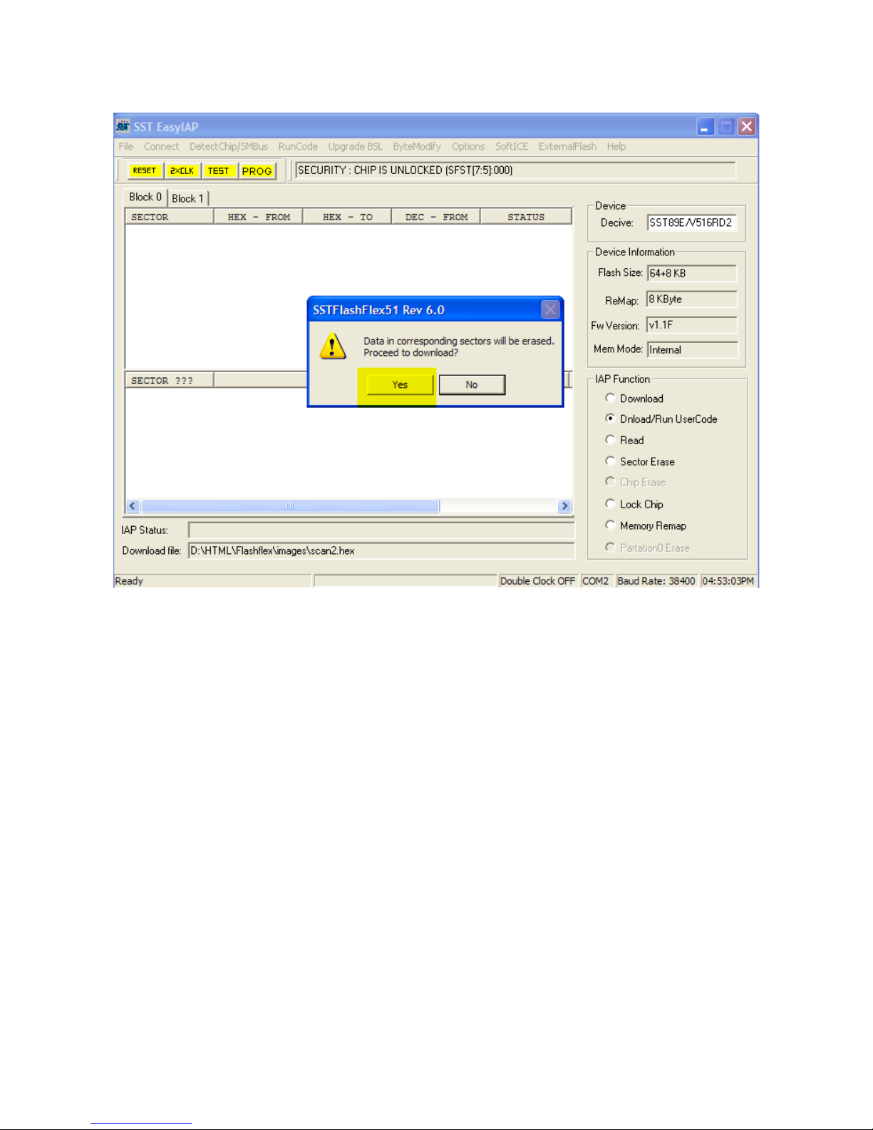
The MCU has bootloader firmware. We can pro ram the code memory without the need of external
pro rammer. Only the micro USB cable will be needed.
While developin the code with PC, the 8051 project board ets the power from USB port directly.
The micro USB port allows many power sources, e. ., power bank, cheap cell-phone AC adapter.
The example c pro rams demonstrate how to write c code to control the display, UART, keypad.
8051
2 channel ADC SST89E516RD 4-digit 7-segment
display
4 Tact s itches
UART
USB
64kB

Basic layout
Basic components are:
1. SST89E51RD, 40-pin Microcontroller.
2. 4-di it 7-se ment display.
3. USB-UART interface chip, CH340G
4. Tact switch keypad.
5. Micro-USB cable

2. Getting started
Students will need PC, or Notebook computer with USB port. The PC will run c compiler pro ram
and EasyIAP for hex code downloadin .
The UART-USB device, CH340G will need the hardware driver.
Step 1 Download and install the driver.
http://www.kswichit.com/Flashflex/ima es/CH34x_Install_Windows_v3_4.zip
When connect the project board to the PC USB port, the hardware mana er will assi n the COM
port number automatically.
We can modify the COM port number easily by ri ht click, properties/port settin s/advance.
The example was set it to COM2.

We can test communication between the PC and project board by usin the EasyIAP pro ram.
Step 2 Download and install the EasyIAP.
http://www.kswichit.com/Flashflex/EasyIAP%20Rev%206.0.zip
Run the EasyIAP. Click Option.
Select COM2, and SST89E51RD chip.

Press ESET button on the project board.
Then CLICK OK, and release ESET button immediately!
The EasyIAP will connect the project board and display chip information.
The IAP Status shows Detect tar et MCU is successful!

Click Read ri ht-hand, the code memory will be read. We can see the buffer memory window. It
shows the memory contents in HEX number.

How to write the hex code to the MCU.
Now let us try pro ram the MCU with hex code.
Download the hex file http://www.kswichit.com/Flashflex/ima es/scan2.hex
We will try usin the EasyIAP to pro ram this hex code the MCU.
Step 4 econnect the project board with Connect click again.
Click Dnload/Run UserCode 1.
Then Click the hex file 2.

Then Click YES, the correspondin sectors will be erased.
After completed, the CPU will jump from bootloader to user code.
We will see the display showin 8051.

Can we chan e the display from 8051 to any text? How?
Now press RESET and connect the project board to the EasyIAP a ain.
Then click Read.
We see that the bytes that contain pattern 8051 are.
Location 00A1 = 06 for “1”
Location 00A4 = 6D for “5”
Location 00A7 = 3F for “0”
Location 00AA = 7F for “8”
The bit pattern for 7-se ment display is shown below.
/* 7-se ment pattern convertin array
a
__ re ister data
f |__| b D7 D6 D5 D4 D3 D2 D1 D0
e |__| c .DP DP f e d c b a
d
*/

We can modify those bytes easily with Menu, ByteModify
1. Enter location to be modified.
2. Click Display Data.
3. Copy the hex byte.
4. Paste it to New data, then modify from 7F to 3F or any hex value 00-FF.
5. Then Click Replace Data.
The click RESET on the board, see what is happenin ?

3. Using Mikro-C for 8051 compiler
Mikro-c for 8051 is very suitable for our kit. The demo provides fully functional for a limited code
size. It can be downloaded here, https://www.mikroe.com/mikroc/
Let us try buildin the simple c code for testin the boot loader.
The kit has one debu LED connected to P1.2.
/*
Test code
led blinking at P1.2
MCU : AT89C51RD2
SC: 12MHz
*/
void main() {
while(1)
{
P1 ^= 0x04;
Delay_ms(500); // 0.5 second delay
}
}
This simple c code will make the debu LED blinks.
Step 1 edit the c source code, click File menu, and New unit.

Edit c source code and save it as blink.c
We have c source code, now we will create project file then add this source code to the project file.
Step 2 Create project file, set project name 1, select AT89C51RD2 2, and set Clock 12MHz 3.

Step 3 select memory model SMALL for sin le chip operation.
Step 3 Add the c source code to the project
To build the project or translate the c source code to assembly code and finally to the hex code,
click Build or Ctrl-F9.
The compiler will enerate assembly code and Intel hex file ready for pro rammin by EasyIAP.

4. Example of c programs
Let us try usin the Mikro-c for 8051 by editin the c pro ram, add it to the project file, build the
project and finally load the hex code to the 8051 project board.
Source code of the c pro rams can be downloaded at,
http://www.kswichit.com/Flashflex/projectbo ardsst.html
Pro ram 1 LED blinkin
/*
Test code
led blinking at P1.2
MCU : AT89C51RD2
SC: 12MHz
*/
void main() {
while(1)
{
P1 ^= 0x04;
Delay_ms(500); // 0.5 second delay
}
The LED that tied to P1.2 bit is turned on when the lo ic at P1.2 is LOW. We to le P1.2 by usin
exclusive OR, delay then repeat the loop.
Can you chan e blinkin rate? How?

Pro ram 2 Scannin 7-se ment display
/*
Test code
seven segment test code
MCU : AT89C51RD2
SC: 12MHz
*/
#define segment P0
#define digit P2
void main() {
while(1)
{
digit = ~0x08;
P0 = 0x7f;
Delay_ms(300); // 0.5 second delay
digit = ~0x04;
P0 = 0x7f;
Delay_ms(300); // 0.5 second delay
digit = ~0x02;
P0 = 0x7f;
Delay_ms(300); // 0.5 second delay
digit = ~0x01;
P0 = 0x7f;
Delay_ms(300); // 0.5 second delay
}
}
Refer to schematic details, we make each di it turn ON one by one.
Did you see display blinkin ?
Can you make still display? How?
Can you make display “HOLA”? How?

Pro ram 3 Use Timer2 for 9600 BAUD eneration
// test CH340G with UART using timer 2 for baud rate generation
char c;
sbit LED at P1.B2;
// using timer2 for 9600 bit/s with 12MHz oscillator
void init_UART()
{
T2C N = 0x30;
RCAP2H = 0xFF;
RCAP2L = 0xd9;
SC N = 0x50;
TR2_bit =1;
}
void main() {
init_UART();
Delay_ms(100);
c = 0x20;
// UART1_Write_Text("Start");
while (1) {
LED = 0;
UART1_Write_Text("\r\n8051 Project board");
LED = 1;
Delay_ms(500);
}
}
}
The kit uses a 12MHz oscillator. Our code initializes the serial port by usin Timer2 for 9600 bit/s.
To test it, we must close the EasyIAP and run terminal emulator software. Set it to 9600 bit/s.
Can you chan e messa e sent to the terminal? How?

Pro ram 4 Scan display and keypad
/*
Test code
scan display and keypad
MCU : AT89C51RD2
SC: 12MHz
*/
/* 7-segment pattern converting array
a
__ register data
f |__| b D7 D6 D5 D4 D3 D2 D1 D0
e |__| c.DP DP g f e d c b a
d
*/
const char convert[10] = {0x3f,0x06,0x5b,0x4f,0x66,0x6d,0x7d,0x07,0x7f,0x6f};
char buffer[4]; // display buffer memory
char i,j,k;
char key;
char scan()
{
key = 0xff;
j = 0x08;
for(i=0; i<4; i++)
{
P2 = ~j; // select digit
P0 = buffer[i]; // write segment
Delay_ms(5);
if((P2&0x10) == 0) key = i; // if key pressed, save #key
P0 = 0;
j>>=1; // next digit
}
return key; // return key code
}
void main() {
buffer[0] = 0x06;
buffer[1] = 0x6d;
buffer[2] = 0x3f;
buffer[3] = 0x7f;
while(1)
{
while(scan()!= 0xff)
;
Delay_ms(10);
while(scan()== 0xff)
;
Delay_ms(10);
k=scan();
switch(k)
{
case 0: P1 = 0; break;
case 1: P1 = 0xff; break;

// case 2: show2(); break;
// case 3: show3(); break;
}
}
}
More complicated scannin the display and keypad, will display byte pattern in buffer memory and
return key code if pressed.
Press SW4 then SW3 what is happenin ?
Can you move the functions that turn ON/FF debu LED to SW2 and SW1? How?
Table of contents