manuals.online logo
Brands
  1. Home
  2. •
  3. Brands
  4. •
  5. Widex
  6. •
  7. Motherboard
  8. •
  9. Widex iP5 User manual

Widex iP5 User manual

1-800-221-0188
www.widexPro.com
Fine Tuning Guide for
Programming the Inteo with
the iP5 Portable Programmer
DIB12/1106
UsingtheiP5toProgramInteo
SelectionofInteoInstrumentStyle
IN-CIC Custom CIC Fits up to 65-70 dB Hearing Loss
IN-X Custom ITE or ITC with High Fits up to 70-75 dB Hearing Loss
Definition Locator
IN-9 BTE with High Definition Locator Fits up to 70-75 dB Hearing Loss
IN-9é Open Fit BTE with High Definition Locator Fits up to 25-30 dB Hearing Loss below
500 Hz and 70-75 dB above 1000 Hz.
IN-19 BTE with High Definition Locator Fits up to 95-100 dB Hearing Loss
Pre-ProgrammingInteo
1. Perform programming in a quiet environment.
2. Connect Inteo to iP5.
a) Select correct programming pill or adaptor boot and attach to programming cable.
b) Confirm that the programming cable is connected to iP5.
c) For CIC models remove battery door and replace door with CIC adaptor.
d) For BTE models insert a new battery.
e) Attach connector(s) to hearing aid(s).
f) Confirm proper connections between all components.
3. Insert Inteo hearing aid(s) into the client’s ear(s).
4. Turn on iP5: Press [on R] for right or [on L]
for left (See A).
Note 1: Only one ear can be fit at a time. In addition adjustments cannot be made, nor data
entered, when the hourglass is active.
Note 2: An Inteo hearing aid that has been programmed and fine tuned with the iP5 program-
mer is completely compatible with Compass. An Inteo hearing aid that has been programmed
and fine tuned with Compass may not be completely compatible with the iP5 programmer. If
an Inteo hearing aid with program specific fine tuning, as a result of unlinking the program
from the Master Program, is connected to the iP5 programmer all programs will be linked to
the Master program and the program specific fine tuning will be recalculated. In addition, if
on Compass the Master program has been moved to a position other than the first position the
iP5 will return it to the first position. The iP5 programmer will always ask if you want to over-
write, or recalculate, the settings according to the format that the iP5 programmer can handle.
Note 3: Conversion between Inteo IN9 and IN9 é cannot be accomplished on the iP5 program-
mer. This conversion can only be made on Compass.
AB
1
IN_IP5_Manual8.qxd 11/28/06 1:12 PM Page 1
b) For steeply sloping audiograms or unusual configurations an expanded Sensogram may
be performed in additional fre q u e n c y re g i o n s . Select [E X P] (see B) to access the
additional frequency regions. Use [= =›] and [‹ = =] to scroll through the frequencies and
select the desired channel(s) for testing. Select [BACK] to exit expanded sensogram mode.
Once the expanded Sensogram mode has been utilized the option to reset [RSET] (see B)
appears in the mode window. Choose reset when you want to return to the basic
Sensogram mode.
Note: It is not necessary to perform the Sensogram for every frequency in the expanded mode.
Only test the frequencies of interest. If expanded frequencies are tested the basic Sensogram
screen will not display thresholds. Open the expanded view to see the Sensogram values.
2. Press [MODE] (see B) to enter Feedback
mode. Perform Feedback test in a quiet
e n v i ronment. Instruct client to “Please
remain quiet throughout the entire test and
open your mouth slightly. A series of sounds
will be pre s e n t e d ”. The feedback test should
t a k e about 15-20 seconds per ear.
Note: A series of dashes (- - -) will be displayed if the environment is not sufficiently quiet for testing.
• Press [TEST] (see B) to begin the Feedback test. If the test needs to be repeated press [TEST]
again.
•Confirm that Feedback values are acceptable. This is indicated in the Feedback window as
“TEST OK”. Insufficient gain for conversational inputs is indicated if the results are displayed
as a series of asterisks (***). Repeat the feedback test.
Note: If appropriate Feedback values cannot be achieved confirm that the hearing aid is appro-
priate for the degree of hearing loss and/or consider earmold/shell modifications.
• You may choose to use estimated feedback data by pressing [MODE] (see B). Answer yes,
when prompted,to use estimated data.
•The in-situ vent effect [INS VENT], as measured by AISA, is displayed as an equivalent vent
diameter in millimeters. The in-situ vent effect is also displayed in the feedback window.
Note: AISA, the Assessment of In-situ Acoustics algorithm, cannot be turned on or off on the
iP5 programmer as it can on Compass. If the detected hearing aid has been previously pro-
grammed on Compass, and AISA had been turned off, [INS VENT ——mm] will be displayed
on the iP5.
• Press [REF] (see B) to view the available
gain for each frequency region. Below these
values are the Minimum Gain (MIN) values
representing the minimum acceptable gain
for a conversational input. Press [BACK]
(see B) to return to the Feedback window.
Inteo programming is complete.
Note: Once the Inteo hearing aid has been pro g rammed the FINE TUNE window will be the
next to appear when the mode button is pressed. FINE TUNE will be the first window to appear
when the iP5 pro g rammer is turned on and a pro g r ammed Inteo is recognized. You can re t u r n
to the Pre c o n d i t i o n s , Sensogram or Feedback mode at any time by pressing the mode button.
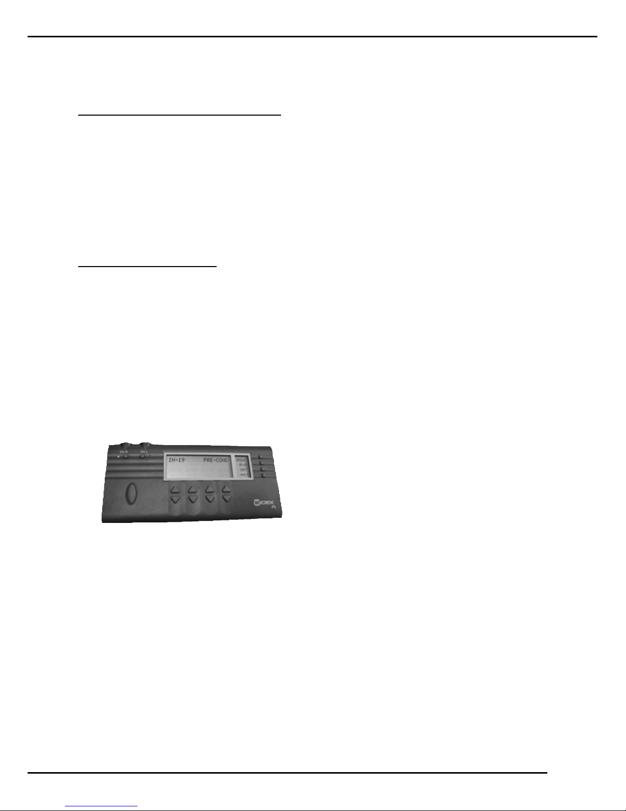
iP5 is now in the Pre-Conditions mode.
1. Choose [M-B] in the mode window (See B)
to designate fitting as monaural or binaural.
Use [ARROW] key to choose MON or BIN.
Press [BACK] to exit [M-B]. An exclamation
point (!) will appear next to [M-B] in the
mode window to indicate that a monaural
fitting has been chosen.
2. Select [VNT]to choose the vent diameter in
millimeters (mm). Use the up or down
[ARROW] key for selection. Press [BACK]
to exit [VNT].An exclamation point (!) will
appear next to [V N T ] in the mode
window to indicate that vent size has been
chosen.
Note: [VNT]is not an available option in an Inteo élan.
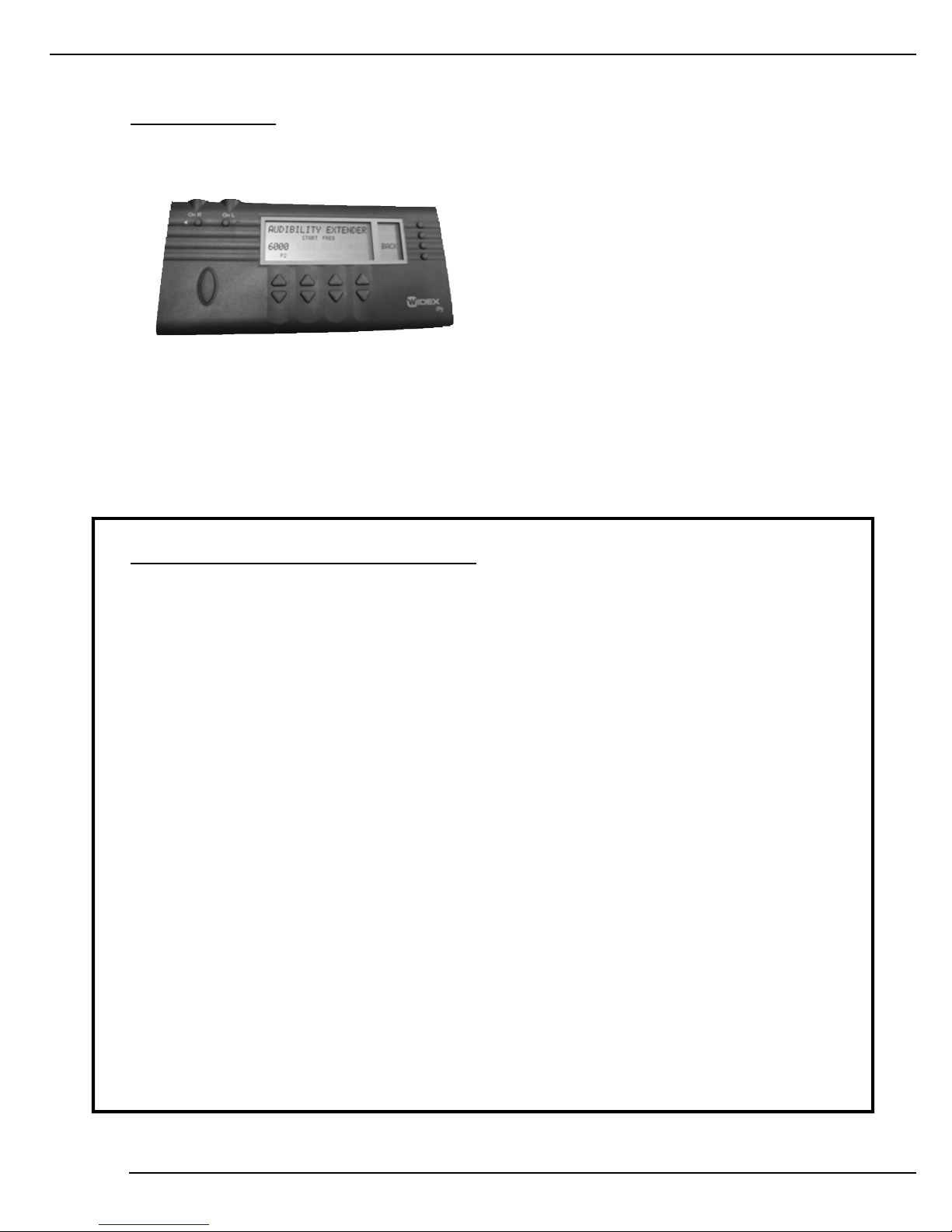
3. Press [= =›] to access [AGE] for the pediatric rationale and [ ABG] to apply an air bone gap
correction factor. Apply the pediatric rationale if the client is under 5 years of age by select-
ing [AGE]. Use the up or down [ARROW] key for selection of age group. Press [BACK] to
exit. An exclamation point (!) will appear in the mode window to indicate application of the
pediatric rationale.
Note: The age correction is necessary for children under 5 years of age even when the
Sensogram is measured.
4. For conductive hearing losses press [ABG]. Enter the air bone gap for each of the four
frequencies by using the up [ARROW] keys in each channel. Press [BACK] to exit [ABG].
An exclamation point (!) will appear next to [ABG] in the mode window to indicate that
air bone gap data have been entered.
Note: Remember to enter the air bone gap for the specific frequency and not the bone conduc-
tion threshold or the average air bone gap.
ProgrammingInteo
1. Press [MODE] (see B) to enter Sensogram
mode.
a) Obtain Sensogram using bra c k e t i n g
approach at 500, 1000, 2000, and 4000
Hz. The number that is flashing repre-
sents the active channel for stimulus pres-
entation. Signal is audible when [TONE]
is displayed.
• Press [UP ARROW] beneath desired channel to increase the presentation level.
• Press [DOWN ARROW] beneath desired channel to decrease the presentation level.
• Press [TONE KEY] (see C) to activate tone.
3
2
B
B
C
B
B
IN_IP5_Manual8.qxd 11/28/06 1:12 PM Page 2
• Press the [UP ARROW] under the desired channel to increase the value. This will
increase gain for inputs above a conversational level.
• Press the [DOWN ARROW] under the desired channel to decrease the value. This will
decrease gain for inputs above conversational level.
• To choose another input level press [INP] in the mode window (see B).
• Press [BACK] (see B) to return to FINE TUNE. An exclamation point (!) will appear in
the mode window next to [IG] to indicate that a change has been made to Insertion
Gain.
c) Adjustments may be made for soft inputs (approximately 20-30 dB HL) in the [(SOFT)INS
GAIN] screen. Insertion gain values and target (TG) values are displayed.
•P r ess the [UP ARROW] under the desired channel to increase the va l u e. This will incre a s e
gain for inputs below a conve r sational leve l .
• Press the [DOWN ARROW] under the desired channel to decrease the value. This will
decrease gain for inputs below a conversational level.
• To choose another input level press [INP] in the mode window (see B).
• Press [BACK] (see B) to return to FINE TUNE. An exclamation point (!) will appear
in the mode window next to [IG] to indicate that a change has been made to
insertion gain.
3. To access Maximum Power Output press
[= =›] in the Fine Tune mode (see B)
f o l l o wed by [M P O]. The display re a d s
[MPO (OUTPUT: dB HL)]. Actual MPO
values are displayed above target (TG)
values for each frequency region. Ideally
these numbers should match in order to
achieve Inteo’s unique Loudness Mapping
criteria, however values may be adjusted
manually if necessary.
•Press the [UP ARROW] under the desired channel to increase MPO values.This will
increase the MPO for all frequencies where output can be increased.
•Press the [DOWN ARROW] under the desired channel to decrease the MPO values. This
will decrease the MPO for all frequencies where output can be decreased.
•Press [BACK] (see B) to return to FINE TUNE. An exclamation point (!) will appear in the
mode window next to [MPO] to indicate that a change has been made to MPO.
The default setting for Inteo is Automatic
Output Control [AOC]on. This prevents
distortion of high outputs. It is recom-
mended that AOC remain active unless the
client requires higher output from the hear-
ing aid even at its maximum gain settings.
Automatic Output Control may be turned
off manually.
FineTuningInteo
1. Turn on iP5: Press [on R] for right or [on L]
for left (See A).
Note: Only one ear can be fine tuned at a time.
2. Press [MODE] if iP5 is not in FINE TUNE
mode (See B).
When in FINE TUNE m o d e you may access the
Loudness Master [L N S ], Insertion Gain [I G ] ,
Maximum Power Output [M P O ] including
Automatic Output Control [AO C ] and Occlusion
Manager [O C C].
1. To access Loudness Master press [LNS]
(see B). The Loudness Master adjusts over-
all gain for all frequency regions.
•Use the [UP ARROW] to increase overall
loudness.
•Use the [DOWN ARROW] to decrease
overall loudness.
•Changes are made in 1 dB steps.
Press [BACK](see B) to return to FINE TUNE. An exclamation point (!) will appear in the
mode window next to [LNS] to indicate that a change has been made to the Loudness Master.
2. To access Insertion Gain [INS GAIN] press
[IG] (see B). Insertion gain values can be
adjusted for each input level; normal, loud
and soft.
a) The first [INS GAIN] screen view reads
[(Normal)INS GAIN]. Insertion gain val-
ues for normal conversational inputs (50-
60dB HL) are displayed above the target
gain values for each frequency region.
The number displayed above the TG value is the actual insertion gain value. Ideally these
numbers should match in order to achieve Inteo’s unique Loudness Mapping criteria, however
values may be adjusted manually if necessary.
• Press the [UP ARROW] under the desired channel to increase the value. This will increase
gain for conversational level inputs.
• Press the [DOWN ARROW] under the desired channel to decrease the value. This will
decrease gain for conversational level inputs.
• To choose another input level press [INP] in the mode window (see B).
• Press [BACK] (see B) to return to FINE TUNE. An exclamation point (!) will appear in the
mode window next to [IG] to indicate that a change has been made to Insertion Gain.
b) Adjustments may be made for loud inputs (approximately 70-80 dB HL) in the [(Loud)
INS GAIN] screen. Insertion gain values and target (TG) values are displayed.
5
4
AB
B
B
B
B
IN_IP5_Manual8.qxd 11/28/06 1:12 PM Page 4
InteoProgramOptions
When in the PROGRAM OPTIONS mode you may access Program Selection [PRG], Remote
Control matching [RC3], Program Gain Offset [PGO], High Definition Locator [LOC], Speech
and Noise [SN] and Feedback Cancelling [FBC].
1. The default setting for programs [PRG] is the Master Program. As many as two acoustic and
two telecoil programs may be selected in addition to the basic Inteo Master program for a
total of five. The Inteo CIC may have a total of three acoustic programs which can be
accessed only when using a remote control. The Inteo Master Program provides the best
overall performance in all environments. Each of the other seven available program options
has a special focus. Those programs are:
• [T] telecoil • [TV] television
• [MT] microphone plus telecoil • [MUS] music
• [AE]audibility extender • [ACC]acclimatization
• [COMF] comfort
The dispenser has the flexibility of placing programs 2 through 5 in their preferred order.
The Master program is always in the first program position when programming with the iP5
programmer.
a) Press [MODE] (see B) to access [PRO-
GRAM OPTIONS].
b) When viewing the PROGRAM OPTIONS
screen note that [P1] beside MAST flashes
to indicate that the first program is the
Master Program. Listening programs that
h a ve previously been selected will be
d i s p l ayed in the P R OGRAM OPTIONS
window but cannot be changed there.
c) Press [PRG] in the mode window (see B). [PROGRAM SELECTION] will be displayed.
[P1] beside MAST flashes.
d) The second program [P2] position is indicated in the lower left of the [PROGRAM SELEC-
TION] screen by a dash [-]. A listening program may be added to this position by press-
ing the up or down [ARROW KEY] beneath to scroll through the available listening
program selections. The order of the program selections, when using the [UP ARROW] to
scroll, is as follows:
• Master [MAST] • Audibility Extender [AE]
• Acclimatization [ACC] • Microphone plus Telecoil [MT]
• Music [MUS] • Telecoil [T]
• Television [TV] • No program [-]
• Comfort [COMF]
The order is reversed when scrolling with the [DOWN ARROW] key.
Use the same procedure to add or change a listening program selection in each available
program position.
• To access Automatic Output Control press [= =>] in the FINE TUNE mode followed
by [MPO].
• Press [AOC] (see B).
• Press [UP ARROW] beneath [OFF].
• Press [BACK] (see B) to return to [MPO].An exclamation point (!) will appear in the
mode window next to [AOC] to indicate that a change has been made to Automatic
Output Control.
Note: When Automatic Output Control is turned off MPO values return to target and further
changes cannot be made.
4. The default setting for Inteo Occlusion
Manager is [O C C ] off. The Occlusion
Manager can be turned o n m a n u a l l y.
Turning Occlusion Manager on de-couples
the low fre q u e n c y channels, below 500 Hz,
f r om the higher fre q u e n c y channels and
i n c rea ses compression for the very low fre-
q u e n cy channels. It further allows for man-
ual gain adjustment of the isolated low fre-
q u e n cyre g i o n s . Ty p i c a l l y , gain is decre a s e d
by making negative offsets for LF1 and/
or LF2.
• To access Occlusion Manager press [= =›] in the Fine Tune mode (see B) followed by
[OCC]. An asterisk (*) appears above [OFF ].
• Press [UP ARROW] beneath [ON]. An asterisk (*) now appears above [ON]. To compare
the two settings alternate between [ON] and [OFF] by pressing the [ARROW KEYS] and
ask the client to select the one that makes their voice sound better.Ask the client to say
“Baby Jeanie is teeny tiny” and note the effect on the hollowness of their voice as they
repeat the phrase.
• For further fine tuning of the Occlusion Manager changes may be made to LF1
(LF1==125,250 and 350 Hz) or LF2 (LF2= 350 and 500 Hz). Gain in the desired chan-
nel can be decreased by pressing the [DOWN ARROW].
Note: If the occlusion is believed to be related to too much low frequency gain then decreasing
LF1 will help to alleviate the problem. Change LF1 for “loudness issues; change LF2 for “clar-
ity” adjustment.
•LF1 is not available on the Inteo élan.
• Press [BACK]( see B) to return to FINE TUNE. An exclamation point (!) will appear in the
mode window next to [OCC] to indicate that a change has been made to the Occlusion
Manager.
Note: If the occlusion is related to the actual physical fit of the hearing aid activating the
occlusion manager may NOT resolve the difficulty.
7
6
B
B
IN_IP5_Manual8.qxd 11/28/06 1:12 PM Page 6
3 . O v e r all gain may be adjusted, in one dB steps for each acoustic listening pro g r am other than the
primary Master Pro g r am and the Audibility Extender, in the [P ROGRAM GAIN OFFS E T ] mode.
Note: [PGO] can only be accessed if additional listening programs have been selected.
a) To access [PROGRAM GAIN OFFSET] press
[PGO] in the [PROGRAM OPTIONS] mode
window (see B).
Note: Audibility Extender is displayed as
[* AE*] in this screen to indicate that the
listening program has been selected but no
change to program offset can be made.
b) Press the [UP ARROW] under the desired listening program to increase the program
gain offset.
Press the [DOWN ARROW] under the desired listening program to decrease the program
gain offset.
c) Press [BACK] (see B) to return to [PRO-
GRAM OPTIONS]. An exclamation point
(!) will appear in the mode window next to
[PGO] to indicate the adjustment of [PRO-
GRAM GAIN OFFSET].
4. The microphone characteristic setting can
be adjusted for each acoustic listening pro-
gram in the [HIGH DEF LOCATOR] mode.
Note: Inteo CIC instruments have only an omnidirectional mode.
a) Press [ = =› ] in the [PROGRAM OPTIONS] mode window (see B).
b) Press [LOC] in the mode window.
c) The current microphone characteristic setting will be displayed for each program.
d) Press the [UP ARROW] or [DOWN ARROW] under the desired listening program to adjust
the microphone setting. The available settings are:
•High Definition Locator with Speech Tracer [LOCS]
•High Definition Directional [DIR]
•High Definition Omnidirectional [OMNI]
•High Definition Locator without Speech Tracer [LOC]
e) Press [BACK] (see B) to return to [PROGRAM OPTIONS]. An exclamation point (!) will
appear in the mode window next to [LOC] to indicate the adjustment of the microphone
characteristic setting.
e) Press [BACK] (see B) to return to [PRO-
GRAM OPTIONS]. An exclamation point (!)
will appear in the mode window next to
[PRG] to indicate the selection of additional
listening programs.
2. Remote Control RC3 matching can be accomplished in the [PROGRAM SELECTION] mode.
a) P ro g r am the RC3 remote control (see
P r o g ramming the RC3 Remote Contro l
instructions).
b) Press [RC3] in the [PROGRAM SELEC-
TION] mode window (see B).
c) [LEFT RC3 MATCHING] or [RIGHT RC3
MATCHING] will be displayed.
d) Press [STRT] in the mode window (see B)
while simultaneously holding down the
center key [ (o) ] on the remote control.
e) MATCH OK appears beneath [LEFT RC3
MATCHING] or [RIGHT RC3 MATCHING].
The remote control model, RC3-1 or RC3-2,
is displayed as is the ID number, the number
of program selections and the setting of the
right/left function when using an RC3-2
remote.
Note: The number of programs in the hearing aid and the number of programs in the
remote control must match. The RC3-1 can hold up to three (3) programs and the RC3-2
can hold up to five (5) programs.
f) When RC3 matching is not successful there are several possible errors:
•No RC3 Data-Hearing aid and RC3 are not communicating i.e. RC3 has not been pro-
grammed, the center key of the RC3 has not been held down during the matching
process, RC3 is out of range (more than 1 meter) or RC3 batteries are dead.
• RC3-1 has a different number of programs than the hearing aid.
• RC3-2 has a different number of programs than the hearing aid.
•ID code is invalid.
g ) P r ess [RS E T ] in the mode window to re-set RC3 matching if necessary.
h) Press [BACK] in the mode window to return to [PROGRAM SELECTION].
i) Press [BACK] (see B) in the mode window to return to [PROGRAM OPTIONS]. An excla-
mation point (!) will appear in the mode window next to [RC3].
Note: When programming both a left and a right hearing aid each aid must be matched to
the RC3 individually.
9
8
B
B
B
B
B
IN_IP5_Manual8.qxd 11/28/06 1:12 PM Page 8
f) Press [BACK] (see B) to return to [PROGRAM OPTIONS]. An exclamation point (!)
will appear in the mode window next to [FBC] to indicate an adjustment to the Feedback
setting.
6. A manual adjustment to Audibility Extender can be made in the Program Options mode.
a ) P r ess [= =›] in the [P R OGRAM OPTIONS]
mode window (see B) twice.
b) Press [FBC] in the mode window.
c) Press [MA] in the mode window.
d) [MANUAL ADJUST] will be displayed. The
default setting is [0].
e) Press the [DOWN ARROW] to lo wer the
max gain in one dB steps to a maximum of
15 dB.
f) Press [BACK] (see B) twice to return to the Program Options mode.
Note: If Feedback Cancellation has been turned off in any other listening programs, the
manual adjustment parameter can also be lowered for that program.
7. The Audibility Extender Start Frequency can be adjusted.
a) P ress [ = =› ] in the [P RO G R A M
OPTIONS] mode window (see B) twice.
b) Press [AE] in the mode window.
c) [AUDIBILITY EXTENDER] will be dis-
played. The default Start Frequency will be
displayed.
d) P ress the [UP ARROW] or [D O W N
ARROW] to adjust the Start frequency.
e) Press [BACK] (see B) to return to [PROGRAM OPTIONS]. An exclamation point will appear
in the mode window next to [AE] to indicate an adjustment to the Start Frequency.
Note: Changing overall Audibility Extender (AE) gain is an option only when programming
with Compass. AE gain cannot be adjusted on the iP5 programmer.
TurnOffiP5
Press [ON R] AND [ON L] simultaneously.
Note: If the iP5 is inactive for more than 5 minutes it will shut off automatically.
BinauralListeningFunction
To provide binaural listening during fitting connect both hearing aids to the iP5. While one of
the hearing aids is active (i.e. Left) push [ON] for the other ear (i.e. [ON R]. The microphones
on both hearing aids will be active. However, program adjustments will only occur in the ear
selected for programming (i.e. Left). Push the [ON] button of the hearing aid you are program-
ming (i.e. [ON L] to deactivate the binaural mode.
5 . The Speech and Noise mode settings can be adjusted for each acoustic listening pro g r am, exc e p t
Audibility Extender, in the [SPEECH – NOISE] mode.
Note: Audibility Extender is displayed as [* AE *] in this screen to indicate that the listening
program has been selected but no change to the speech and noise setting can be made.
a) Press [= =› ] in the [PROGRAM OPTIONS]
mode window (see B).
b) Press [SN] in the mode window.
c) The current setting for the Speech and Noise
mode will be displayed.
d) P r ess the [UP ARROW] or [D O WN ARROW]
under the desired listening pro g r am to change
the Speech and Noise setting.
e) The order of the available options, when using the [UP ARROW], is:
•Speech Enhancer [SPNH]
•Noise Reduction Off [OFF]
•Classic Noise Reduction Minimum [W1]
•Classic Noise Reduction [W2]
•Classic Noise Reduction Enhanced [W3]
•Noise Reduction Comfort [COMF]
The order is reversed when scrolling with the [DOWN ARROW].
f) Press [BACK] (see B) to return to [PROGRAM OPTIONS]. An exclamation point (!) will
appear in the mode window next to [SN] to indicate an adjustment to the Speech and
Noise setting.
5. The Feedback Cancellation settings can be adjusted for each acoustic listening program,
except Audibility Extender, in the [FEEDBACK CANCELLING] mode.
Note: Audibility Extender is displayed as [* AE *] in this screen to indicate that the listening
program has been selected but no change to the feedback cancelling setting can be made.
a) Press [= =› ] in the [PROGRAM OPTIONS]
mode window (see B) twice.
b) Press [FBC] in the mode window.
c ) The current setting for the Fe e d b a c k
Cancelling mode will be displaye d .
d ) P r ess the [UP ARROW] or [D O WN ARROW]
under the desired listening pro g ram to
change the Feedback Cancelling setting.
e) The order of the available options, when using the [UP ARROW], is:
•Super Gain [STD]
•Super Gain Max [MAX]
•Super Gain Music [MUS]
• Off [OFF]
The order is reversed when scrolling with the [DOWN ARROW].
11
10
B
B
B
B
IN_IP5_Manual8.qxd 11/28/06 1:12 PM Page 10
InteoTestMode
The Test Mode allows the clinician to compare the output of the hearing aid against factory
specifications. The hearing aid is set to a fixed frequency gain setting during this measurement.
1. Turn off the iP5 by pressing [ON R] AND
[ON L] simultaneously.
2. Connect the Inteo hearing aid to the appro-
priate inlet [ON L or ON R].
3. Hold down the top right menu key while
pressing the appropriate [ON] key.
4. [TEST MODE] is displayed. The hearing aid
is in test mode.
5. Connect Inteo to the coupler of the hearing aid test system and follow ANSI-1996 for
evaluating the Inteo hearing aid.
6. Press [TELE] to evaluate telecoil function.
7. When testing a BTE instrument open the battery door, when testing is completed, to restore
the hearing aid to regular functioning.
ProgrammingtheRC3RemoteControl
1. Insert the batteries in the remote control and replace the compartment cover.
2 . Within 10 seconds, press and hold down the center key while pressing the upper left key (+).
3. The word Pro will appear in the display window.
4. Press the center key. The display window will show the RC3 model.
5. Press the center key. The display window will show the maximum number of programs the
remote can handle. Change the number of programs by using the up/down keys on the right
side of the remote. The number of programs in the remote must be the same number of pro-
grams in the hearing aid.
6. Press the center key. The display window will show the setting of the short-term log func-
tion. The default setting is off. Change the setting using the up/down keys on the right side
of the remote. Turning it on will enable the short-term logging feature of the aid.
7. To enable separate adjustment of the right and left hearing aids (RC3-2 only), press the cen-
ter key. The display window will show the current setting. The default setting is "Uni,"
which means the remote will adjust both aids simultaneously Use the up/down arrow keys
on the right side to change the setting to "Sep," which will adjust each aid individually.
8. To enable the timer function (RC3-2 only), press the center key. The display will show the
current setting of the timer function. The default setting is "AL OFF." Change the setting
using the up/down arrow keys on the right side of the remote.
9. To set the RC3 options, press the center key. The display window will show "Opt." All
options are set to default values, and it is normally not necessary to change these during
the initial programming of the RC3.
10. To end programming, press the center key again.
B
12
IN_IP5_Manual8.qxd 11/28/06 1:12 PM Page 12

Popular Motherboard manuals by other brands

ASROCK M3A785GXH/128M brochure

ASROCK

ASROCK M3A785GXH/128M brochure

SMSC EVB-EMC1043 user manual

SMSC

SMSC EVB-EMC1043 user manual

Azoteq IQ Switch IQS127 user manual

Azoteq

Azoteq IQ Switch IQS127 user manual

Aaeon EMB-9658T Mini-ITX user guide

Aaeon

Aaeon EMB-9658T Mini-ITX user guide

Asus P5N-MX - Motherboard - Micro ATX quick start guide

Asus

Asus P5N-MX - Motherboard - Micro ATX quick start guide

ASROCK H110M-DGS user manual

ASROCK

ASROCK H110M-DGS user manual

Altera Enpirion EN6360QI user guide

Altera

Altera Enpirion EN6360QI user guide

IEI Technology KINO-9452 user manual

IEI Technology

IEI Technology KINO-9452 user manual

Foxconn IGPSK7MA series user manual

Foxconn

Foxconn IGPSK7MA series user manual

Embest SBC6345 user guide

Embest

Embest SBC6345 user guide

Gigabyte GA-8N-SLI Pro manual

Gigabyte

Gigabyte GA-8N-SLI Pro manual

MPS EV6001DN-00D quick start guide

MPS

MPS EV6001DN-00D quick start guide

Biostar TZ77B Setup manual

Biostar

Biostar TZ77B Setup manual

Foxconn H55MXV LE user manual

Foxconn

Foxconn H55MXV LE user manual

AKM AKD4133-A manual

AKM

AKM AKD4133-A manual

GIGA-BYTE TECHNOLOGY GA-F2A55M-S1 user manual

GIGA-BYTE TECHNOLOGY

GIGA-BYTE TECHNOLOGY GA-F2A55M-S1 user manual

Grasslin talento taxxi plus operating instructions

Grasslin

Grasslin talento taxxi plus operating instructions

Asus TUF Z390-PRO GAMING quick start guide

Asus

Asus TUF Z390-PRO GAMING quick start guide

manuals.online logo
manuals.online logoBrands
  • About & Mission
  • Contact us
  • Privacy Policy
  • Terms and Conditions

Copyright 2025 Manuals.Online. All Rights Reserved.