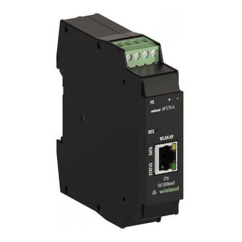
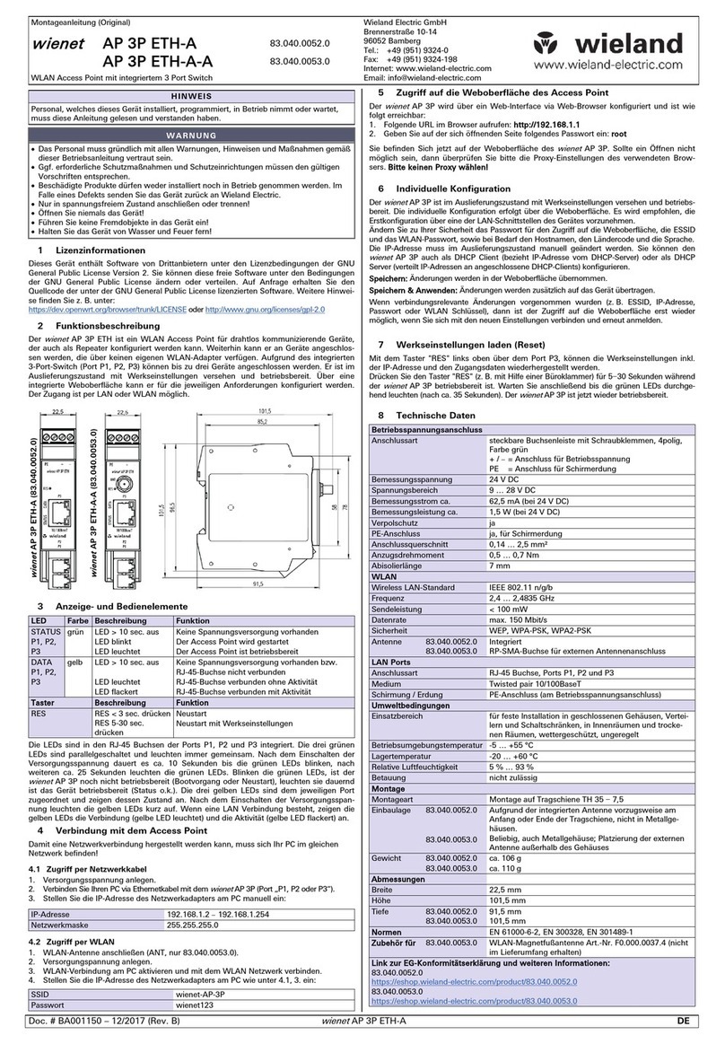
Wieland WIENET AP User manual

User manual
Doc. No. BA001098
Last Update: 12/2022 (Rev. C)
WIENET AP
WLAN Access Point

Info
Wieland Electric GmbH | BA001098 | 12/2022 (Rev. C)
2
INFO
This work is copyrighted material. The resulting rights remain with Wieland Electric GmbH. Any du-
plication of this document or parts thereof is permitted only within the limits of the statutory provi-
sions of the Copyright Act. Alteration or abridgment of this document without the express written
consent of Wieland Electric GmbH is prohibited.
wienet is a brand of Wieland Electric GmbH. Other product and brand names mentioned in this man-
ual are trademarks or registered trademarks of their respective owners. Use of these names and
trademarks by third parties for their own purposes may violate proprietary rights.

Table of Contents
Wieland Electric GmbH | BA001098 | 12/2022 (Rev. C)
3
TABLE OF CONTENTS
1About this manual 7
1.1 Function of this document 7
1.2 Scope and revision level 7
1.3 Target group 7
1.4 Function and structure of this manual 7
1.5 Symbols and notations 8
2Safety 9
2.1 Qualified persons 9
2.2 Proper use 9
3General information about the access point 10
4Scope of supply 11
5Product description 12
5.1 Model versions 12
5.2 Order numbers 12
5.2.1 Model versions 12
5.2.2 Accessories 13
5.3 Dimensions 13
5.4 Mounting Recommendations 14
5.4.1 Installation position of AP ETH-A and AP 3P ETH-A model version 14
5.4.2 Installation position of AP ETH-A-A and AP 3P ETH-A-A model version 14
5.5 User interfaces (connections) 14
5.6 Status indications 15
5.7 DC supply 15
5.8 Antenna connector ANT (only for AP ETH-A-A and AP 3P ETH-A-A) 16
5.9 Ethernet port 16
5.10 Restart 17
5.10.1 Restart by pressing the reset button 17
5.10.2 Restarting via the web interface 17
5.11 Factory reset 17
5.11.1 Reset using the reset button 17
5.11.2 Resetting via the web interface 17
5.12 OpenWRT 18
5.13 Maintenance 18
6Initial start-up 19

Table of Contents
Wieland Electric GmbH | BA001098 | 12/2022 (Rev. C)
4
6.1 Connection of the access points before initial start-up 19
6.2 Starting the access point 19
6.3 Configuring the access point 19
6.3.1 Access via network cable 19
6.3.2 Access via WLAN 19
6.3.3 Connection to the web interface 19
6.3.4 Initial configuration 20
7Scenarios for use 21
7.1 Configuration as an access point 21
7.2 Configuration as an access point with DHCP 22
7.3 Configuration as a network bridge (repeater) 23
7.4 Configuration as a cable replacement 24
8Web interface of the access point 25
8.1 Access to the web interface 25
8.2 General information about the web interface 26
8.2.1 Saving changes 26
8.2.2 Automatic reloading 26
8.3 Language setting and design 26
8.4 Time zone and device name 27
8.4.1 Logging 28
8.4.2 Time synchronization 28
8.5 Password and SSH access 29
8.5.1 Router password 29
8.5.2 SSH access 29
8.5.3 SSH key 30
8.6 LAN interface 30
8.6.1 Configuring network interfaces 30
8.6.2 Devices 35
8.6.3 Global network settings 38
8.7 Switch (VLAN) configuration (only AP-3P-ETH-x) 38
8.8 Wireless network (WLAN) 39
8.8.1 WLAN adapter configuration 40
8.8.2 WLAN network configuration 42
8.8.3 Display of available wireless networks 45
8.8.4 Display of connected WLAN devices 45
8.9 DHCP and DNS 45
8.9.1 General settings 46
8.9.2 Resolve and host files 47

Table of Contents
Wieland Electric GmbH | BA001098 | 12/2022 (Rev. C)
5
8.9.3 TFTP settings 47
8.9.4 Advanced settings 48
8.9.5 Static entries 48
8.10 Computer name 49
8.11 Static routes 50
8.11.1 General settings 50
8.11.2 Advanced settings 51
8.12 Diagnoses 51
8.13 Firewall 51
8.14 Backup/firmware update 52
8.14.1 Backing up the device configurations 52
8.14.2 Restoring a backup 52
8.14.3 Resetting the factory device configuration 53
8.14.4 Updating the firmware 53
8.15 Restart 53
8.16 System protocol 53
8.17 Real-time diagrams 54
8.18 Firewall 54
8.19 Routes 55
8.20 Kernel protocol 55
8.21 Processes 55
8.22 Channel analysis 56
8.23 System overview 56
8.24 Package management 57
8.25 System start-up 57
8.26 Scheduled tasks 58
8.27 LED Configuration 58
8.28 Wi-Fi timer 59
8.28.1 Timer 59
8.28.2 Displaying the log file and cron jobs 60
8.29 Terminal 60
8.29.1 Terminal 60
8.29.2 Config 60
8.30 uHTTPd 61
8.30.1 General settings 62
8.30.2 All web server settings 62
8.30.3 Advanced settings 63
8.30.4 uHTTPd self-signed certificate parameters 64
8.31 OpenVPN 65

Table of Contents
Wieland Electric GmbH | BA001098 | 12/2022 (Rev. C)
6
8.31.1 Step-by-step instructions 66
8.31.2 Creating a client on the VPN portal 68
8.31.3 Simplified configuration 73
8.31.4 Advanced settings 76
9Technical data 77
9.1 Operating voltage connection 77
9.2 WLAN 77
9.3 LAN 77
9.4 Environmental conditions 78
9.5 Installation 78
9.6 Dimensions 78
9.7 Standards 78
9.8 Accessories 78
10 Disposal 79
11 Service and Support 80
12 Appendix 81
12.1 List of figures 81
12.2 List of tables 84
12.3 List of keywords 85

About this manual
Wieland Electric GmbH | BA001098 | 12/2022 (Rev. C)
7
1ABOUT THIS MANUAL
Please read this chapter carefully before working with this user manual and the wienet access point.
1.1 Function of this document
This user manual for wienet access points describe the device, its functions and the basic device
configuration.
1.2 Scope and revision level
This manual is valid for wienet access points ETH-A, ETH-A-A, 3P ETH-A and 3P ETH-A-A. The assem-
bly instructions and the product user manual can be downloaded from the Wieland eShop. Always
ensure that you are reading the information in the latest version of this user manual. The version
and revision date are indicated on the title page and in the footer.
1.3 Target group
The target group for this user manual are technicians, particularly qualified electricians, planning
and managing wireless networks. The access points are generally used in the construction of switch-
boards.
1.4 Function and structure of this manual
This user manual provides technical staff with information about the assembly, programming, oper-
ation, basic configuration and diagnosis of wienet access points.
The chapter on 2 Safety, p. 9 contains basic safety instructions. Please read and follow these instruc-
tions in each case.
Additional information is available on our website www.wieland-electric.de. You can also download
the following files on wienet routers, switches and access points:
•Product information
•Data sheets
•Assembly instructions
•Drawings
NOTE

About this manual
Wieland Electric GmbH | BA001098 | 12/2022 (Rev. C)
8
1.5 Symbols and notations
The "DANGER" symbol indicates an imminent danger. If it is not avoided, it can result in death or se-
rious injury.
"DANGER" is used to warn against risks that already apply at the time of the warning (e.g. hot sur-
faces, sharp edges, pinch points, etc.).
It is used exclusively in danger of personal injury!
The "WARNING" symbol indicates a possible danger. Failure to observe this symbol may result in se-
rious injury.
The "CAUTION" symbol indicates a potential danger. Ignoring this symbol can result in minor inju-
ries.
Notes concerning the special functions of the device.
Instructions tell you about a potentially harmful situation. If it is not avoided, the system or some-
thing around it can be damaged.
DANGER
WARNING
CAUTION
NOTE

Safety
Wieland Electric GmbH | BA001098 | 12/2022 (Rev. C)
9
2SAFETY
This chapter describes the safety instructions for you and the operators of the devices. Carefully
read this chapter before you start work with an access point.
General safety instructions
•Any person installing, programming, operating or servicing wienet access points must have read
and understood this user manual.
•The staff must be thoroughly familiar with all warnings, instructions and requirements contained
in this manual.
•The corresponding local safety, protective and installation requirements must be met.
The user is solely responsible for selecting the correct products and technical version in accordance
with the corresponding local regulations.
2.1 Qualified persons
The installation, configuration for operation, commissioning and servicing of wienet access points
may only be carried out by qualified persons.
Qualified persons:
•have appropriate technical training and
•have access to the assembly instructions and user manual for the wienet access points, which
have been read and understood.
2.2 Proper use
The wienet Access Point has a WLAN interface (IEEE 802.11 n/b/g) and one or three Ethernet-10/100
MBit/s connections, depending on the model, and can be operated in various modes. The device has
therefore been designed to connect wired Ethernet-10/100 MBit/s networks or devices with other
networks or network devices via WLAN.
Please observe the following instructions:
•Do not use the access point for any other purposes.
•The access point may only be used in accordance with current international and national regula-
tions, as well as in accordance with all special restrictions on the use of the access points in pre-
scribed applications and environments.
•Only use original accessories to prevent injuries as well as damage to the devices and to ensure
that all relevant regulations have been adhered to. Prohibited changes or the use of non-ap-
proved accessories may damage the access point and violate existing laws. Prohibited changes or
the use of non-approved accessories may void warranty claims.
•The access point may not be opened.
•The voltage at the feeder connection of the access point may not be exceeded (see Section 9 Tech-
nical data, page 77).
•Do not expose the access point to extreme environmental conditions. Protect the access point
against dust, humidity and high temperatures.
•It is recommended that you make a copy or backup of all major settings stored in the device
memory.
Any other application or change to the device –even during assembly and installation –will result in
the voiding of any warranty claims against Wieland Electric GmbH.
WARNING
WARNING

General information about the access point
Wieland Electric GmbH | BA001098 | 12/2022 (Rev. C)
10
3GENERAL INFORMATION ABOUT THE ACCESS
POINT
The wienet AP ETH-A, AP ETH-A-A, AP 3P ETH-A and AP 3P ETH-A-A access points are used to estab-
lish a WLAN connection between various devices via an Ethernet interface (10/100 MBit/s) using the
Internet or LAN, or to connect various WLAN-LAN networks with each other.
The standard wienet AP ETH-A and AP ETH-A-A access points have an Ethernet 10/100 MBit/s port.
The standard wienet AP 3P ETH-A and AP 3P ETH-A-A access points have three Ethernet
10/100 MBit/s ports and an integrated WLAN interface (IEEE 802.11 n/b/g).
Configuration is carried out via a password-protected web interface. The web interface provides de-
tailed statistics about the activities of the access point and the signal strength, as well as a detailed
protocol. The access point supports functions such as DHCP and NTP, among others. Thanks to the
OpenWRT open-source operating system on which it is based, the access point can be configured
and operated in many ways.
Examples of possible applications:
•Extension of an Ethernet cable network by adding WLAN functions
•Integration of wired network devices (e.g. PLC controls) into an existing WLAN
•Replacement of network connections that are difficult to wire with transparent WLAN bridges
•Expansion of existing WLAN networks
•Integration of mobile machines such as robots operating autonomously in a network
•Establishment of a secure VPN tunnel via LAN or WLAN

Scope of supply
Wieland Electric GmbH | BA001098 | 12/2022 (Rev. C)
11
4SCOPE OF SUPPLY
The basic access point scope of supply includes the following:
•Access point
•Assembly instructions
In addition to the basic components, the following accessories can be ordered:
•15854 WIFI antenna
•15874v2 WIFI ROOF ANT. antenna
These accessories can be ordered online from the Wieland eShop. More detailed information about
the accessories and the corresponding article numbers may be found in Chapter 5.2.2 Accessories,
page 13.

Product description
Wieland Electric GmbH | BA001098 | 12/2022 (Rev. C)
12
5PRODUCT DESCRIPTION
5.1 Model versions
Table 1: Model versions
Type with 1 Ethernet
port
Type with 3 Ethernet ports
Antenna
AP ETH-A
AP 3P ETH-A
Integrated
AP ETH-A-A
AP 3P ETH-A-A
External (connection via RP-SMA)
5.2 Order numbers
5.2.1 Model versions
Table 2: Article number for model version with 1× Ethernet 10/100BaseT and integrated antenna
AP ETH-A
83.040.0050.0
WLAN industrial design access point, WLAN standard IEEE 802.11 n/g/b, integrated
antenna, 1× Ethernet 10/100BaseT, administration via web interface, operating volt-
age: 24 VDC, protection class IP20, DIN mounting rail assembly,
W × H × D: 22.5 × 98.6 × 91.5 mm
with integrated antenna
Table 3: Article number for model version with 1× Ethernet 10/100BaseT and connection for external antenna
AP ETH-A-A
83.040.0051.0
WLAN industrial design access point, WLAN standard IEEE 802.11 n/g/b, antenna
connector, external RP- SMA, 1× Ethernet 10/100BaseT, administration via web in-
terface, operating voltage: 24 VDC, protection class IP20, DIN mounting rail assem-
bly, W × H × D: 22.5 × 98.6 × 91.5 mm
with connection for an external antenna
Table 4: Article number for model version with 3× Ethernet 10/100BaseT and integrated antenna
AP 3P ETH-A
83.040.0052.0
WLAN industrial design access point, WLAN standard IEEE 802.11 n/g/b, integrated
antenna, 3× Ethernet 10/100BaseT, administration via web interface, operating volt-
age: 24 VDC, protection class IP20, DIN mounting rail assembly,
W × H × D: 22.5 × 101.5 × 91.5 mm
with integrated antenna
Table 5: Article number for model version with 3× Ethernet 10/100BaseT and connection for external antenna
AP 3P ETH-A-A
83.040.0053.0
WLAN industrial design access point, WLAN standard IEEE 802.11 n/g/b, antenna
connector, external RP- SMA, 3× Ethernet 10/100BaseT, administration via web in-
terface, operating voltage: 24 VDC, protection class IP20, DIN mounting rail assem-
bly, W × H × D: 22.5 × 101.5 × 101.5 mm
with connection for an external antenna

Product description
Wieland Electric GmbH | BA001098 | 12/2022 (Rev. C)
13
5.2.2 Accessories
Table 6: Article numbers for accessories
15854 x antenna
F0.000.0037.4
WIFI/WLAN antenna for roof installation; 2.4 GHz ISM band for WIFI/WLAN, Bluetooth
and Zigbee; RP- SMA/M connector; antenna dimensions 223× 29 mm; with 2.5 m ca-
ble
15874v2 WIFI ROOF ANT. antenna
F0.000.0037.5
wienet omnidirectional roof antenna v2 –7 dBi exterior antenna; frequency range
2.4/ 5 GHz(WLAN); range 7 dBi; connector 1 × RP- SMA/M; antenna dimensions
82 × 48 × 48 mm, incl. bracket (mast and wall mounting); with 5 m cable
5.3 Dimensions
Fig. 1: Dimensions of access points 83.040.0050.0 and 83.040.0051.0 (in mm)
Fig. 2: Dimensions of access points 83.040.0052.0 and 83.040.0053.0 (in mm)

Product description
Wieland Electric GmbH | BA001098 | 12/2022 (Rev. C)
14
5.4 Mounting Recommendations
The mounting instructions provided together with the device should be taken into account during
assembly.
The access point is designed to be mounted on a DIN TH 35 –7.5 mounting rail.
Please take into account the low-voltage directive when mounting the access point in the control
cabinet.
5.4.1 Installation position of AP ETH-A and AP 3P ETH-A model version
Position the access point at the start or end of the mounting rail, due to its integrated antenna. Do
not use this model version in metal housings or metal control cabinets.
5.4.2 Installation position of AP ETH-A-A and AP 3P ETH-A-A model version
You can use this model version in metal housings or metal control cabinets. The position on the
mounting rail does not affect the operation of the device. Position the external WLAN antenna out-
side the housing.
5.5 User interfaces (connections)
Table 7: Access point connections
Name
Connection
Description
+
Screw terminal
Connection for +24 VDC power supply
–
Screw terminal
Connection for ground/GND power supply
PE
Screw terminal
Connection for shield grounding
ETH, P1, P2, P3
RJ-45
Connection to the LAN network
ANT *
RP-SMA
Connection for the external WLAN antenna
* applies for AP ETH-A-A and AP 3P ETH-A-A devices
Fig. 3: Front view of AP ETH-
A
Fig. 4: Front view of AP ETH-
A-A
Fig. 5: Front view of
AP 3P ETH-A
Fig. 6: Front view of
AP 3P ETH-A-A
NOTE
NOTE

Product description
Wieland Electric GmbH | BA001098 | 12/2022 (Rev. C)
15
5.6 Status indications
Table 8: Status indications
Name
Color
Description
STATUS
Green
Does not light up after
10 s
No power supply available
Blinking
Access point is starting up
Remains on
Access point is ready for use
DATA
Yellow
Does not light up after
10 s
No power supply available or RJ-45
socket not connected
LED flickers
RJ-45 socket connected with network
activity
Remains on
RJ-45 socket connected without net-
work activity
RES
–
Press RES (< 3 s)
Reset, restart
Press RES for 5-30 s
Reset to factory settings and restart
5.7 DC supply
Connect the DC supply voltage with the corresponding polarity to the access point.
Take note of the permitted voltage and current values for the device (see Table 11: Technical data:
Operating voltage connection, page 77).
Ensure the correct polarity of the network connection.
Fig. 7: Connection to power supply
Use a screwdriver to fasten the connection cables to the corresponding screw terminal.
Before switching on the power supply, ensure that the connection cables are correctly fastened in
the screw terminals.
CAUTION
CAUTION

Product description
Wieland Electric GmbH | BA001098 | 12/2022 (Rev. C)
16
5.8 Antenna connector ANT (only for AP ETH-A-A and AP 3P ETH-A-A)
The antenna is connected to the access point via an RP-SMA connector on the front panel.
The access point is not ready for operation unless the antenna is connected to the antenna socket
labeled "ANT."
Fig. 8: Example of an antenna
The antenna is connected by screwing the RP-SMA/M antenna plug into the RP-SMA connector (ANT)
at the access point.
Fig. 9: Connecting the external antenna
5.9 Ethernet port
Table 9: Pin assignment of Ethernet-Port ETH (RJ-45)
Pin
signal
description
Data flow direction
1
TXD (+)
Transmit Data –positive pole
Input/Output
2
TXD (–)
Transmit Data –negative pole
Input/Output
3
RXD (+)
Receive Data –positive pole
Input/Output
4
-
-
5
-
-
6
RXD (–)
Receive Data –negative pole
Input/Output
7
-
-
8
-
-
Fig. 10: Ethernet plug (RJ-45)
This access point does not support a supply via PoE (Power-over-Ethernet)! However, the device can
still be operated on a network with PoE.
NOTE
NOTE

Product description
Wieland Electric GmbH | BA001098 | 12/2022 (Rev. C)
17
5.10 Restart
5.10.1 Restart by pressing the reset button
You can reset the access point by inserting a pointed object (such as a metal pin) into the opening in
the front panel of the access point labeled RES and pressing the button behind the opening for < 3
seconds during operation. Wait approximately 35 seconds until the STATUS LED (green) is perma-
nently lit. The restart is complete.
5.10.2 Restarting via the web interface
You can reset the access point by selecting the Restart menu item in the System menu on the web
interface and then selecting Restart. Wait approximately 35 seconds until the STATUS LED (green) is
permanently lit. The restart is complete.
5.11 Factory reset
Please note the difference between resetting and restarting the access point.
A reset is a restart of the device during which the factory settings for the device are restored.
Please note that when resetting the factory settings, the current individual access point configura-
tion settings will be deleted. If necessary, you should save your configuration before resetting.
5.11.1 Reset using the reset button
You can reset the access point to the factory settings by inserting a pointed object (such as a metal
pin) into the opening in the front panel of the access point labeled RES and pressing and holding the
button in the opening > 5 seconds during operation. All settings will be irrevocably deleted. Wait a
maximum of 90 seconds until the STATUS LED (green) is permanently lit. The device is now reset to
the factory settings.
5.11.2 Resetting via the web interface
You can reset the access point to the factory settings by selecting the Backup/Firmware menu item
in the System menu on the web interface and then pressing the Reset button. All settings will be ir-
revocably deleted. Wait a maximum of 90 seconds until the STATUS LED (green) is permanently lit.
The device is now reset to the factory settings.
See also Chapter 8.14.3 Resetting the factory device configuration, page 53.
NOTE

Product description
Wieland Electric GmbH | BA001098 | 12/2022 (Rev. C)
18
5.12 OpenWRT
The access point described in this user manual makes use of an adaptation of the free OpenWRT op-
erating system published under the GNU General Public License v2. More detailed information about
the operation of the access point can thus be found at https://openwrt.org and in the associated
secondary literature. At https://openwrt.org you will have access to the official documentation for
the operating system, as well as to a user wiki and an internet forum.
You are permitted to modify or distribute this free software under the conditions of the GNU General
Public License. If required, you can request the source code of the software covered by the GNU
General Public License. You can find further information at http://www.gnu.org/licenses/gpl-2.0.
5.13 Maintenance
Do not use any corrosive chemicals, solvents or abrasive cleaning agents when cleaning the access
point!
NOTE

Initial start-up
Wieland Electric GmbH | BA001098 | 12/2022 (Rev. C)
19
6INITIAL START-UP
6.1 Connection of the access points before initial start-up
Before operating the access point for the first time, you need to connect all the components re-
quired to run your application:
•Power supply
•Ethernet cable
•External antenna (only for AP ETH-A-A and AP 3P ETH-A-A model versions)
The access points are only ready for operation when the Ethernet cable and power supply are con-
nected. An external antenna must also be connected to the AP ETH-A-A and AP 3P ETH-A-A device
types.
6.2 Starting the access point
The first step when setting up the access point is to connect the power supply to the access point.
Connect the access point to a network switch or directly to a device (e.g. a PC or laptop). The factory
setting for the IP address is 192.168.1.1. After a successful start, the STATUS LED (green) will remain
on.
The performance of the access point can be set via the web interface.
Take note of the permitted voltage and current values for the device (see Table 11: Technical data:
Operating voltage connection, page 77).
Ensure the correct polarity of the network connection.
6.3 Configuring the access point
The access point is configured via the web interface. To establish a network connection via an Ether-
net cable or WLAN, your PC must be part of the same network. The DHCP server in the access point is
deactivated as a default state; you will therefore need to configure the PC you are using with an IP
address within the address range 192.168.1.2–254.
6.3.1 Access via network cable
For this purpose, you need to connect the PC used for configuration with the Ethernet port of the
access point (directly or via a network switch).
6.3.2 Access via WLAN
Activate the WLAN connection of your PC and connect it to the network with the SSID wienet-AP us-
ing the factory-set password wienet123 configured in the AP.
6.3.3 Connection to the web interface
To configure the device, call up the URL of the access point http://192.168.1.1 in your web browser
and log in with the user name 'root' and the factory-configured password 'root'.
You are now on the web interface of the access point. If you are unable to establish a connection,
check the proxy settings of the web browser you are using. Please do not use an HTTP proxy to con-
nect to the access point.
NOTE
CAUTION

Initial start-up
Wieland Electric GmbH | BA001098 | 12/2022 (Rev. C)
20
6.3.4 Initial configuration
When setting up the access point for the first time, set the time zone, the host name of the device,
and the web interface language. The configuration of these elements is described in Chapter 8 Web
interface of the access point, page 25.
Important: For security reasons, change the password for the user root and the key for the wireless
network during configuration.
Table of contents
Other Wieland Wireless Access Point manuals
Popular Wireless Access Point manuals by other brands
ZyXEL Communications
ZyXEL Communications PLA450 v2 datasheet

Ruckus Wireless
Ruckus Wireless ZoneFlex 7761-CM installation guide

ABB
ABB ABB-free home System manual
UTILITY
UTILITY ROCKET V1.0 user guide
Enterasys
Enterasys RoamAbout R2 Quick installation guide
Snap One
Snap One Araknis Networks quick start guide
