WILD EDGE SL40CRM User manual

40V 2.0AH LI-ION CORDLESS REEL
MOWER INSTRUCTION MANUAL
Model No. SL40CRM
PLEASE READ THIS INSTRUCTION MANUAL CAREFULLY AND MAKE SURE YOU UNDERSTAND
BEFORE USING THE MACHINE, ALSO PLEASE SAVE IT FOR FUTURE REFERENCE.
Any questions please call the customer line on: 800-960-7525 from 9 a.m. –4 p.m., PST, Monday-Friday.

1
Content
1 Technical data.............................2
2 Important safety instructions....3
3 Part identification.......................5
4 Assembly......................................6
5 Operation.....................................11
5.1 Cutting height adjustment........12
5.2 Handlebar operation angle
adjustment................................15
8 Cleaning and maintenance.......21
9 Storage........................................21
10 Guarantee...................................21
11 Exploded view............................22
12 Part list.......................................23
6 Rechargeable battery..................17
7 Additional safety instructions for
battery and charger....................20

2
1TECHNICAL DATA
WARNING! The vibration emission during actual use of the mower can differ from the declared
total value depending on the ways in which the tool is used.
There is the need to identify safety measures to protect the operator that are based on an estimation
of exposure in the actual conditions of use (taking account of all parts of the operating cycle such
as the times when the tool is switched off and when it is running idle in addition to the trigger
time).
Residual risks
Even when the tool is used as prescribed it is not possible to eliminate all residual risk factors.
The following hazards may arise in connection with the tool’s construction and design:
1) Damage to lungs if an effective dust mask is not worn.
2) Damage to hearing if effective hearing protection is not worn.
Health defects resulting from vibration emission if the mower is being used over longer period
of time or not adequately managed and properly maintained.
WARNING! This machine produces an electromagnetic field during operation. This field may
under some circumstances interfere with active or passive medical implants. To reduce the risk of
serious or fatal injury, we recommend persons with medical implants to consult their physician and
the medical implant manufacturer before operating this machine.
Battery type
40V Lithium-Ion
Charging time
Approx. 120 mins
Model No.
SL40CRM
No-load speed
1000 RPM
Height adjustments
Low
Med
High
0.8 inch
1.6 inch
2.4 inch
Cutting width
16 inch
Working time
Approx.30 mins
Weight (included battery)
24lbs
Noise level
96dB
Vibration Value
2
Allowable battery charging
temperature range
50℉–95℉

3
2IMPORTANT SAFETY INSTRUCTIONS
WARNING! Read these instructions carefully, be familiar with the controls and the proper use of
the machine. Please keep the instructions safe for further use!
Operation
⚫Never allow children or people unfamiliar with these instructions to use the machine. Local regulations may
restrict the age of the operator. When not in use store the machine out of reach of children.
⚫This appliance is not intended for use by persons (including children) with reduced physical, sensory or
mental capabilities, or lack of experience and knowledge, unless they have been given supervision or
instruction concerning use of the appliance by a person responsible for their safety. Children should be
supervised to ensure that they do not play with the appliance.
⚫Never mow while people, especially children or pets, are nearby.
⚫The operator or user is responsible for accidents or hazards occurring to other people or their property.
⚫While mowing, always wear substantial footwear and long trousers.
⚫Do not operate the machine when barefoot or wearing open sandals, always wear substantial footwear and
long trousers.
⚫Thoroughly inspect the area where the machine is to be used and remove all stones, sticks, wires, bones and
other foreign objects.
⚫Before using, always visually inspect to see that the blades, blade bolts and cutter assembly are not worn or
damaged. Replace worn or damaged blades and bolts in sets to preserve balance.
⚫Mow only in daylight or in good artificial light.
⚫Avoid operating the machine in wet grass, where feasible.
⚫Always walk, never run.
⚫Never operate the appliance with defective guards, or without safety devices, for example deflectors and/or
grass catchers, in place.
⚫Working on banks can be dangerous.
–Do not mow excessively steep slopes.
–Always be sure of your footing on slopes or wet grass.
–Mow across the face of slopes, Never up and down.
–Exercise extreme caution when changing direction on slopes.
⚫Use extreme caution when stepping back or pulling the machine towards you.
⚫Never mow by pulling the mower towards you.
⚫Stop the blades if the machine has to be tilted for transportation when crossing surfaces other than grass and
when transporting the machine to and from the area to be mowed.
⚫Switch on the motor according to instructions and with feet well away from the blade(s).
⚫Do not tilt the machine when starting or switching on the motor, except if the machine has to be tilted for
starting in long grass. In this case, do not tilt if more than absolutely necessary and tilt only the part which is
away from the operator. Always ensure that both hands are in the operating position before returning the
machine to the ground.
⚫Switch on the motor according to the instructions with feet well away from rotating parts.
⚫Do not put hands or feet near or under rotating parts. Keep clear of the discharge opening at all times.
⚫Always stand clear of the discharge zone when operating the machine.
⚫Never pick up or carry the machine while the motor is running.

4
Remove the safety key
⚫Whenever you leave the machine;
⚫Before clearing a blockage;
⚫Before checking, cleaning or working on the machine;
⚫After striking a foreign object, Inspect the machine for damage and make repairs as necessary;
⚫If the machine starts to vibrate abnormally (check immediately).
Maintenance
⚫Keep all nuts, bolts and screws tight to be sure that the machine is in safe working condition.
⚫Check the grass catcher frequently for wear or deterioration.
⚫Examine the machine and replace worn or damaged parts for safety.
⚫Ensure replacement cutting means of the right type are used.
⚫Ensure that batteries are charged using the correct charger recommended by the manufacturer. Incorrect use
may result in electric shock, overheating or leakage of corrosive liquid from the battery.
⚫Always wear gardening gloves when handling or working near the sharp blades.
Recommendations for optimal handling of the battery
⚫Ensure the switch is in the off position before inserting battery. Inserting the battery into machines that have
the switch on invites accidents.
⚫Keep the battery charger away from rain or moisture. Penetration of water in the battery charger increases
the risk of an electric shock.
⚫Recharge only with the charger specified by the manufacturer. A charger that is suitable for one type of
battery may create a risk of fire when used with another battery.
⚫Do not charge other batteries. The battery charger is suitable only for charging lithium ion batteries within
the listed voltage range. Otherwise there is danger of fire and explosion.
⚫Keep the battery charger clean. Contamination can lead to danger of an electric shock.
⚫Before each use, check the battery charger, cable and plug. If damage is detected, do not use the battery
charger. Never open the battery charger yourself. Have repairs performed only by a qualified technician and
only using original spare parts. Damaged battery chargers, cables and plugs increase the risk of an electric
shock.
⚫Do not operate the battery charger on easily inflammable surfaces (e.g. paper, textiles, etc.) or surroundings.
The heating of the battery charger during the charging process can pose a fire hazard.
⚫Use only batteries intended specifically for the machine. Use of any other batteries may create a risk of
injury and fire.
⚫When battery is not in use, keep it away from other metal objects like paper clips, coins, keys, nails, screws,
or other small metal objects that can make a connection from one terminal to another. Shorting the battery
terminals together may cause burns or a fire.
⚫Do not open the battery. Danger of short-circuiting and injury.
⚫Protect the battery against heat, also against continuous sun irradiation and fire. There is danger of
explosion.
⚫Do not short-circuit the battery. There is danger of explosion.
⚫Protect the battery against moisture and water.
⚫Store the battery only within a temperature range between 40℉ and 104℉. As an example, do not leave the
battery in the car in summer.

5
3PART IDENTIFICATION
1. Operation Lever
2. Safety Lock-out Button
3. Upper Handle
4. Adjusting knob
5. Lower Handle
6. Handle Fixed Wing
7. Grass Bag
8. Wheels
9. Battery Case Cover
10.Main Unit
11. Battery Pack
12. Battery Lock Button
13.Battery Release Button
14. Charger
15. Charging Status LED Indicator
1
3
5
7
9
2
4
6
8
11
14
15
10
12
13

6
4ASSEMBLY
ForYour Safety
1) Switch off, always remove the safety key and battery pack before adjusting or cleaning.
2) Do not touch the rotating blade.
Unpacking
This product requires easy install. Carefully remove the product from the box. Inspect the product
carefully to make sure no breakage or damage occurred during shipping.
Do not discard the packing material until you have carefully inspected and satisfactorily operated
the product.
If you think any parts are missing, first check the packaging again before calling the customer line.
MowerAssembly
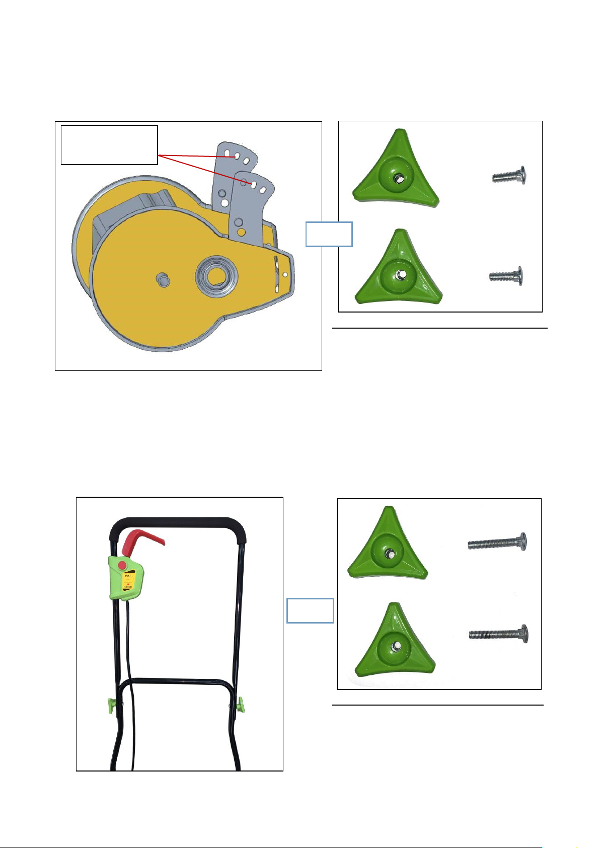
1. Fit the Lower Handle (5) onto the large lug located on the Handle Fixed Wing (6). Fit one side
and then flex the other side of the handle until it fits the opposite lug. (See Figure 1)
WARNING! Do not bend the lower handle to fit both ends at the same time as this may reduce the
width of the lower handle section and it becomes insecure on the retaining pins. Ensure both ends
of the bottom handle are slotted over the two lugs and are hard against the lug end stops to ensure
these do not slip off. Bend slightly outwards if necessary and refit.
WARNING
Before assembly, please DO NOT put the battery
pack into cavity until finished assembly and ready
to start.
Lug
Lower handle
Fig.1
7
Middle hole of the
fixed wing.
2. Fix the lower handle by tightening up 2 sets of Adjusting Knobs (4) and M6*20mm square
neck bolts on two sides of the Handle Fixed Wing (6) thru the middle hole. (See Figure 2)
2 sets of adjusting knobs and short bolts
3. Assemble the Upper Handle (3) to the Lower Handle (5). Use 2 sets of the Adjusting knob (4)
and M6*40mm square neck bolts to secure in place. Make sure that the Upper Handle (3) is
facing up (safety button facing up). (See Figure 3) If you have incorrectly assembled this part,
disconnect and re-assemble in the correct orientation. The knobs should be positioned on the
outside of the handle and the bolts on the inside.
2 sets of adjusting knobs and long bolts
Fig.3
Fig.2

8
4. Once the handle is assembled, connect the plug on the handle cable to the socket on the Main
Unit (10). Tighten up the screw ring to secure the cable. (See Figure 4)
5. Secure the cable to the handle bar by using the three cable clips. (See Figure 5)
3 cable clips
Fig.5
Fig.4

9
6. Attach the Grass Bag (7) to the mower base.
NOTE: Grass bag is an auxiliary option. This mower can
be used with or without the grass bag.
Step 1:
Place the left and right grass bag square bars onto the related
hooks as shown in figure 7.
Step 2:
Wrap the security belt, located on the back of the grass bag,
around the center joint of the lower handle and lock buckle
into place, as shown in below picture. (See Figure 8)
Please note the length of the security belt can be adjusted by
modifying the loop length to meet your own demands.
7. In order to provide simple storage function, the upper handle is foldable design. Just loosen
the long bolts a little bit on each side and then fold forward the upper handle. Then you will be
able to drag the mower for moving. But please make sure to take the battery out before do this.
(See Figure 6)
Fig.6

10
To Load Battery Pack
1) Open the Battery Case Cover (9).
2) Fully insert the Battery Pack (11) into the battery cavity until the Battery Lock Button (12)
bounces back to its normal position. Close the battery case cover securely.
To Remove Battery Pack
To remove the battery pack, withdraw it from the tool while pulling the Battery Release Button (13)
down. (See Figure 9)
NOTE: Watch your fingers due to the
battery is a tight fit to put in and take
out.
Fig.9
11
5OPERATION
WARNING! Please DO NOT repeatedly or rapidly
switch off and on.
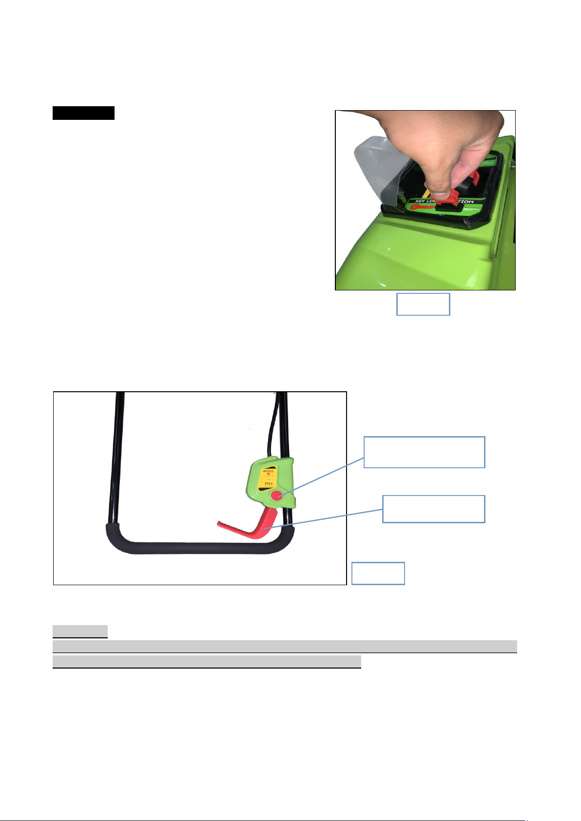
Starting
•Make sure the safety key is inserting into the slot.
(See Figure 10)
•Press and hold the Safety Lock-out Button (2).
•Pull the Operation Lever (1) upward to the handle to
start the mower while holding the safety lock-out button.
•When the motor is starting to run you can release the
Safety Lock-out Button (2). (See Figure 11)
Stopping
Release the Operation Lever (1), the motor will be switched off. (See Figure 11)
CAUTION
We suggest to take out the mower locking key before storage after each time operation. Please DO
NOT lose it, otherwise it will not be able to start off this machine.
Fig.10
Safety Lock-out Button (2)
Operation Lever (1)
Fig.11

12
5.1 CUTTING HEIGHTADJUSTMENT
WARNING! This mower is set to the MEDIUM height cutting position as for default setting.
Always REMOVE the battery pack from cavity before adjusting the mower cutting height.
You can raise up or lower down the cutting position to the best suited for your yards. There are
three levels for your cutting height options.
To Adjust Blade Height
To prevent overloading the mower when cutting high and thick grass, it is recommended to make
one cut at the ‘High’ setting, then another cut at a ‘Medium’ setting. Adjust the mower to the
desired height as follows:
1. Always take out the battery pack and remove the grass bag for easier operation.
2. Loosen the two adjusting knobs from left and right side of the machine body frame, to allow
movement of the metal height adjustment plate. It is not necessary to remove the knob. (See
Figure 12)
Three Cutting Height Levels
Low
Med
High
4/5 inch or 20 mm
1 3/5 inch or 40 mm
2 2/5 inch or 60 mm
Fig.12
13
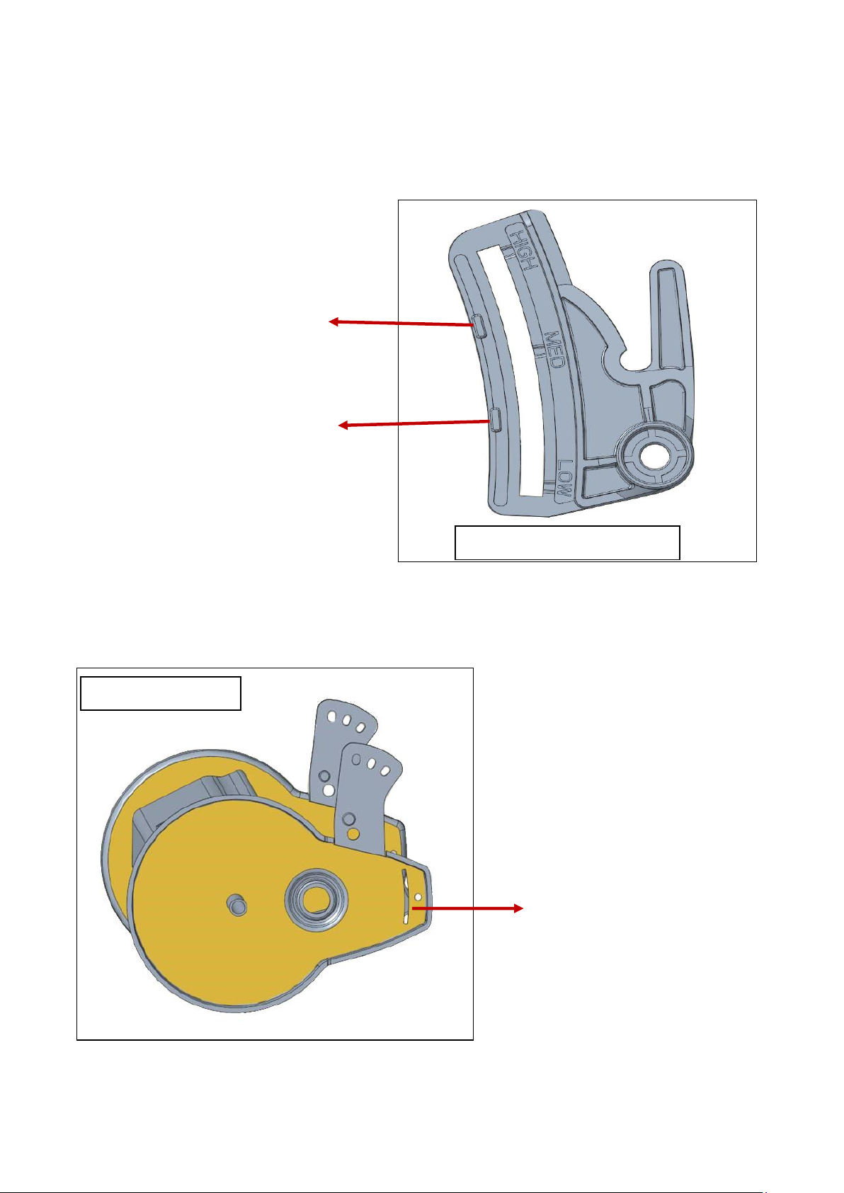
3. Slide this metal plate up and down to the right and proper cutting height position of ‘LOW’,
‘MED’ or ‘HIGH’. There are two stop blocks on the metal plate and one strip-type groove on
the inner side of machine body edge for better fixed effect. (See below graphs)
Upper Stop Block
Lower Stop Block
Stripe-type Groove
Metal HeightAdjustment Plate
Machine Body Frame
14
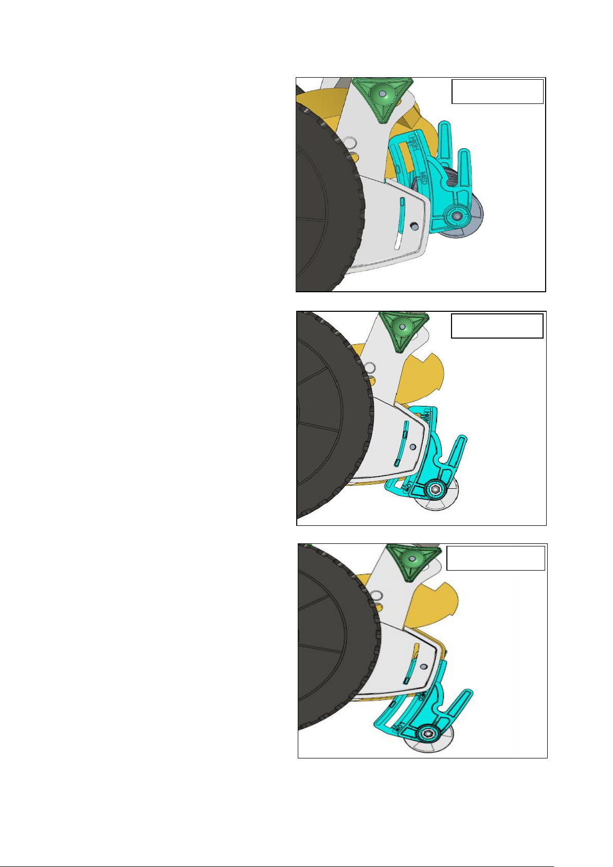
-Low Cutting Height Position
Based on this cutting height position, the
lower stop block on the metal adjustment plate
will just be stuck in the top of groove, then
thread the square neck bolt through the ‘LOW’
marked point on the metal plate and that hole
located on machine body frame, then tighten
up by using adjusting knob and the steel
washer. Ensure that the roller is fitted flat and
another side on the same height position,
finish all the same steps and screw up the
adjusting knobs on both sides simultaneously.
-Medium Cutting Height Position
With this cutting height position, the two stop
blocks are both wedging into the groove of
machine body frame. Lower block will just
approach to the bottom of groove, then tighten
up by using adjusting knob and the steel
washer. Ensure that the roller is fitted flat and
another side on the same height position,
finish all the same steps and screw up the
adjusting knobs on both sides simultaneously.
-High Cutting Height Position
When you slide the metal adjustment plate to
cutting position “High”, the upper stop block
on metal plate will be easy stuck in the groove
and fixed on the bottom of it as right picture
displays. Then tighten up by using adjusting
knob and the steel washer. Ensure that the
roller is fitted flat and another side on the same
height position, finish all the same steps and
screw up the adjusting knobs on both sides
simultaneously.
‘LOW’Position
‘MED’Position
‘HIGH’Position

15
5.2 HANDLEBAR OPERATION ANGLE ADJUSTMENT
Meanwhile, in order to provide the best operation experience and working performance, each
cutting height level matches different handle bar pushing angles.
There are three different angle point holes located on the Handle Fixed Wing (6), you will need to
switch the angle of handle bar during different cutting height position. Left and right side of handle
bar can only be locked onto the same position angle point holes.
Handle Fixed Wing
Uppermost hole for cutting height ‘LOW’.
Middle hole for cutting
height ‘MED’.
Lowermost hole for
cutting height ‘HIGH’.

16
BladeAdjustment and Lubrication
WARNING! Blades are extremely sharp, to avoid injury be careful not to touch blades when make
adjustments. Remove the battery before adjusting the blades.
Blades have been pre-adjusted prior to leaving factory, mis-alignment can sometimes occur; this
can be caused by blades being too loose or too tight against the cutting bar. This can cause an
uneven cut or make the mower hard to push. To correct misalignment, adjustments to the cutting
bar are needed. Each end of the cutting bar can be adjusted separately. Turn the two adjustment
nuts clockwise to tighten; this moves the cutting bar closer in towards the blade. Turn the two
adjustment nuts anti-clockwise to loosen and move the cutting bar further away from the blade.
NOTE: Adjusting the nuts while making blade
adjustments is a very sensitive procedure. A turn
of 1/16in is considered a major adjustment.
Before tightening one adjustment nut, make sure
to adjust the opposite nut an equal amount.
Do not over-tighten adjustment nut, as this
could damage cutting bar.
Check for correct adjustment, to insert a piece of paper between the cutting cylinder and the
straight blade.
Check with a piece of paper at each end of the blade to ensure correct adjustment along the length
of the blade. When the cutting cylinder is turned by hand the paper should be cut cleanly.
If the paper is not cut then gradually tighten the nuts until the paper can be cut cleanly.
To maintain maximum run time and smooth, efficient cutting performance, an oil or spray
lubricant can be applied to the edge of the straight blade and the shaft bearings.
Adjustment Nut

17
Over Current Protection
WARNING! The Mower is equipped with a “Over current protection” setting up. It activates if the
blade gets jammed, clogged or the motor is overloaded because you are trying to cut grass that is
much too long, or wet. The machine will stop when this happens.
Only start the mower again after removing all obstacles or obstructions, change the cutting height
to its highest position or waiting until the grass has dried out. Then you can start the mower
normally.
Mowing
To obtain a clean cut, push the unit in straight lines (passes) at a deliberate walking pace. Overlap
the passes to even the cut and to avoid any uncut strips.
If you hear the motor in the unit change pitch dramatically while mowing, it may be overloaded.
Attempting to force the mower to cut may damage the motor.
Check to see if the grass is very thick or long, a first cut with height set high position will help
reduce the load on the motor. (See Cutting Height Adjustment section)
Push the unit more slowly when cutting thick, long, or wet grass.
The area of cut depends on the lawn conditions, grass thickness, grass length, moisture content,
and height of cut.
For the maximum area of cut it is recommended to cut the lawn more frequently, mow in dry
conditions, select a high cutting height, and walk at normal speed.
Start mowing around the edges of the area to be mowed, then cut the central area in strips
Mowing Using Grass Bag (IncludedAccessory)
The Grass Bag (7) collects the clippings as it mows. It attaches at the grass bag hooks on
the mower and by the strap to the mower handle. Mow using the same procedure as for normal
mowing.
6RECHARGEABLE BATTERY
Charging Battery
Before attempting to charge the battery pack, thoroughly read all Safety Instructions.
The battery needs to be charged before first use and whenever it fails to produce sufficient power
on jobs that were easily done before.
The battery may become warm while charging; this is normal and does not indicate a problem.
NOTE: After several charge and discharge cycles, the battery will attain full capacity.

18
1) Plug the charger into an appropriate AC power outlet. The green indicator (13) lights on to tell
you that the charger is ready for use.
2) Insert the battery pack (3) into the charger (11), as shown in Figure 14, making sure the pack is
fully seated in the charger. The red indicator (12) lights on to tell you that the battery pack is
on charge.
3) The battery pack will be fully charged in about 120 mins. The green indicator (13) keeps green
on to tell you that the battery pack is fully charged.
Red indicator
Green indicator
Power
OFF
ON
charging
ON
OFF
Fully charged
OFF
ON
WARNING
Please DO NOT charge the battery at ambient
temperature below 50ºF or above 95ºF .
Fig.14

19
Important Charging Notes
CAUTION
The new battery already requires charging for 12 hours for the first 3 times of use. You can then
normally charge the battery as described below.
⚫After normal usage, your battery pack should be fully charged in about 120 mins. Allow the
battery to cool down before charging after using the mower. (NOTE: A hot battery placed in
the charger will not charge)
⚫DO NOT charge the battery pack in an air temperature below 50℉or above 95℉. This is
important and will prevent serious damage to the battery pack. Longest life and best
performance can be obtained if battery pack is charged when air temperature is about 75℉.
⚫While charging, the charger may hum and become warm to touch. This is a normal condition
and does not indicate a problem.
⚫If the battery pack does not charge properly
-Check current at receptacle by plugging in a lamp or other appliance.
-Check to see if receptacle is connected to a light switch which turns power off when you
turn out the lights.
-Move charger and battery pack to a surrounding air temperature of 40℉to 104℉.
-If the receptacle and temperature are OK, and you do not get proper charging contact
customer services.
⚫The battery pack needs to be charged before first using and should be recharged when it fails
to produce sufficient power on jobs which were easily done previously. DO NOT CONTINUE
using this product with its battery pack in a depleted condition. (NOTE: Only after several
charge and discharge cycles, the battery will attain full capacity.)
⚫To prolong battery life, avoid leaving the battery pack on charger for extended periods of time
(over 30 days without use). Overcharging can reduce overall battery life directly.
⚫The battery pack will reach optimum performance after being cycled 3 times during normal
usage. There is no need to run the batteries down completely before recharging. Normal usage
is the best method of discharging and recharging the batteries.
Table of contents
Popular Lawn Mower manuals by other brands

GreenWorks Commercial
GreenWorks Commercial CZ60S24X Operator's manual

Husqvarna
Husqvarna CZE 4818 Operator's manual

Jacobsen
Jacobsen LDEA130 Safety and operation/maintenance and parts manual

Stihl
Stihl RM 545 instruction manual

McHale
McHale Pro Glide F3100 Operator's instruction manual

Toro
Toro 22200TE Operator's manual


Challenge Xtreme
Challenge Xtreme XSZ40 operating instructions

Bertolini
Bertolini BTS 80 Use and maintenance

Craftsman
Craftsman 917.370861 owner's manual

Makita
Makita DLM462 instruction manual

Texas
Texas XTB 46 W user manual

Western Auto
Western Auto Western Auto 917.259930 Operation and Operation and service instructions