8
OPM-174/A
system installation. The information in this manual is offered
only as a guide to finalizing your installation plans.
WARNING: PERSONAL INJURY
The enclosures on these units can become very hot
adjacent to the exhaust areas. Special care must be taken
when installing these units to insure that the risk of
contact by people is minimized.
The unit’s main frame should be bolted to a pad that meets
local code. Various materials, including concrete and
composites, are acceptable as long as they are structurally
sound supporting the weight of the unit and preventing
movement during operation. The mounting holes on
the base of this unit are 0.625” in diameter. The engine-
generator is mounted on a sub-frame which is isolated with
special shock mounts on the main frame. This allows the
engine-generator to vibrate without affecting the control
panel on the main frame.
Do not install any shock mounts between the base frame
and the pad. Engine vibration will be transmitted to the
control panel causing erroneous start/stop cycles and
premature control failure.
These units should be mounted a minimum of 24” from a
structure. This will allow for ample room to maintain and
work on the generator set.
Units must be installed in accordance with all local, state,
and national codes. Consult your local agency for specific
requirements.
VENTILATION REQUIREMENTS
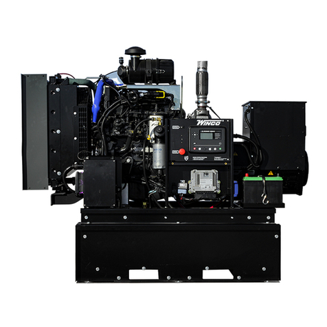
OPEN SKID
WARNING: EQUIPMENT DAMAGE
It is the installer’s responsibility to ensure that there is
sufficient cooling air available to prevent the engine
and generator from over heating. Damage caused by
overheating is not covered by warranty.
Providing proper air movement during your installation
planning is essential. You will need to provide a fresh air
inlet as well as a hot air outlet (to the outside of protection
housing) for proper engine performance. These engine-
generator sets are equipped with unit mount radiators and
the engine is equipped with a pusher type fan. The hot
air from the face of the radiator must be ducted out of the
enclosure to ensure proper cooling. Failing to do so will
allow the hot air to recirculate around the radiator causing
the engine to overheat, resulting in an engine shutdown
and damage. If louvers are used in front of the hot air duct
to protect the unit from outside weather, the louvers should
be 1½ times as large as the area of the radiator face to
prevent back pressure.
Foam or other seals can be used to form a tight lip forcing
all of the air from the engine fan out of the enclosure.
In addition to a hot air discharge, you must plan a fresh air
intake opposite the radiator discharge. Their fresh air inlets
should be 1½ to 2 times larger than the radiator face. The
INSTALLATION
This unit should be installed in a well ventilated area,
ensuring the exhaust air cannot be recirculated back into
the engine.
CAUTION:
This unit will get hot while it is running and for some time
afterward.
WARNING
Before proceeding with the installation, be sure
the engine control is in the “stop” position and the
emergency stop depressed. Also, be sure the generator
MLCB (main line circuit breaker) is in the “off” position and
the unit starting battery is disconnected.
PRIME POWER
Some configurations of the PSS65F4 are available with
EPA Prime power certifications. These configurations are
outfitted with a catalyst to meet current regulations. When
operating prime power derate the load at least 10% for a
variable load. If the load is continuous at one current rating
ensure that it does not exceed 80% of the standby rating.
Prime power configurations can be installed in mobile
or stationary applications as long as sound engineering
practices are followed to accommodate the structural
and cooling considerations outlined in this manual.
Prime applications will require close observation of actual
conditions requiring a shortening of maintenance intervals.
GENERAL INFORMATION
Before beginning the installation process, recheck the
voltage, phase, and amperage rating of the generator
set. Be certain it can handle the intended load and is
compatible with the intended loads. Plans for installation
should be prepared with proper attention to mechanical
and electrical engineering detail to assure a satisfactory
system installation. The installation must comply with all
national, state, and local codes.
The information in this manual is offered only as a guide to
finalizing your installation plans and does not substitute for
sound engineering judgment for the specific application.
ENGINE-GENERATOR SET MOUNTING
These engine-generator sets are designed to be mounted
on a pad where there is proper ventilation. The transfer
switch is mounted next to your electrical entrance or
distribution panel inside or outside the building. Consult
a qualified, licensed electrician or contractor to install and
wire the transfer switch. The installation must comply with
all national, state and local codes. Before beginning the
installation process check the rating of the generator set
and its transfer switch rating. Be certain they can handle
the intended load and are compatible with the entrance
voltage, phase and current ratings. Plans for installation
should be prepared with proper attention to mechanical
and electrical engineering detail to assure a satisfactory
