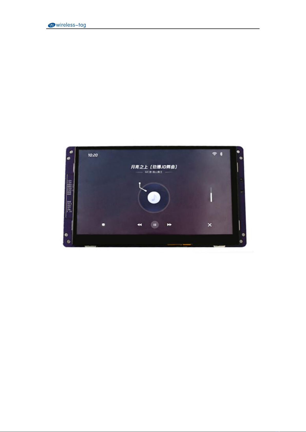
SSD201/202 7-inch Smart Display User manual
2/14
Wireless-Tag Technology Co., Limited http://www.wireless-tag.com
Contents
SigmastarSSD201/202........................................................................................................................ 1
7-inch Smart Display User Manual.....................................................................................................1
1. Overview......................................................................................................................................... 3
2. Technical Parameters.......................................................................................................................4
2.1 Hardware Parameters......................................................................................................... 4
2.2 Electrical Parameters..........................................................................................................5
2.3 Use Environment Parameters.............................................................................................5
3. Interface Description....................................................................................................................... 5
3.1 Motherboard Interface Diagram........................................................................................ 5
3.2 Power Interface/RS232/RS485.......................................................................................... 6
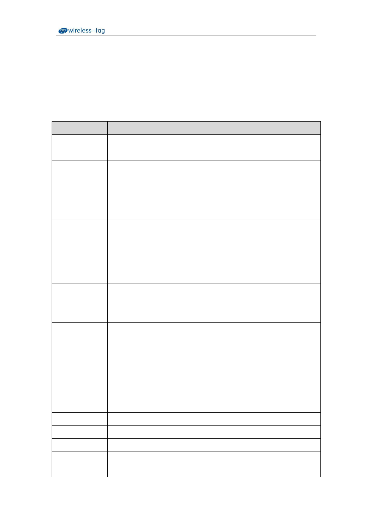
3.3 RGB Interface.................................................................................................................... 7
3.4 TP Interface........................................................................................................................ 9
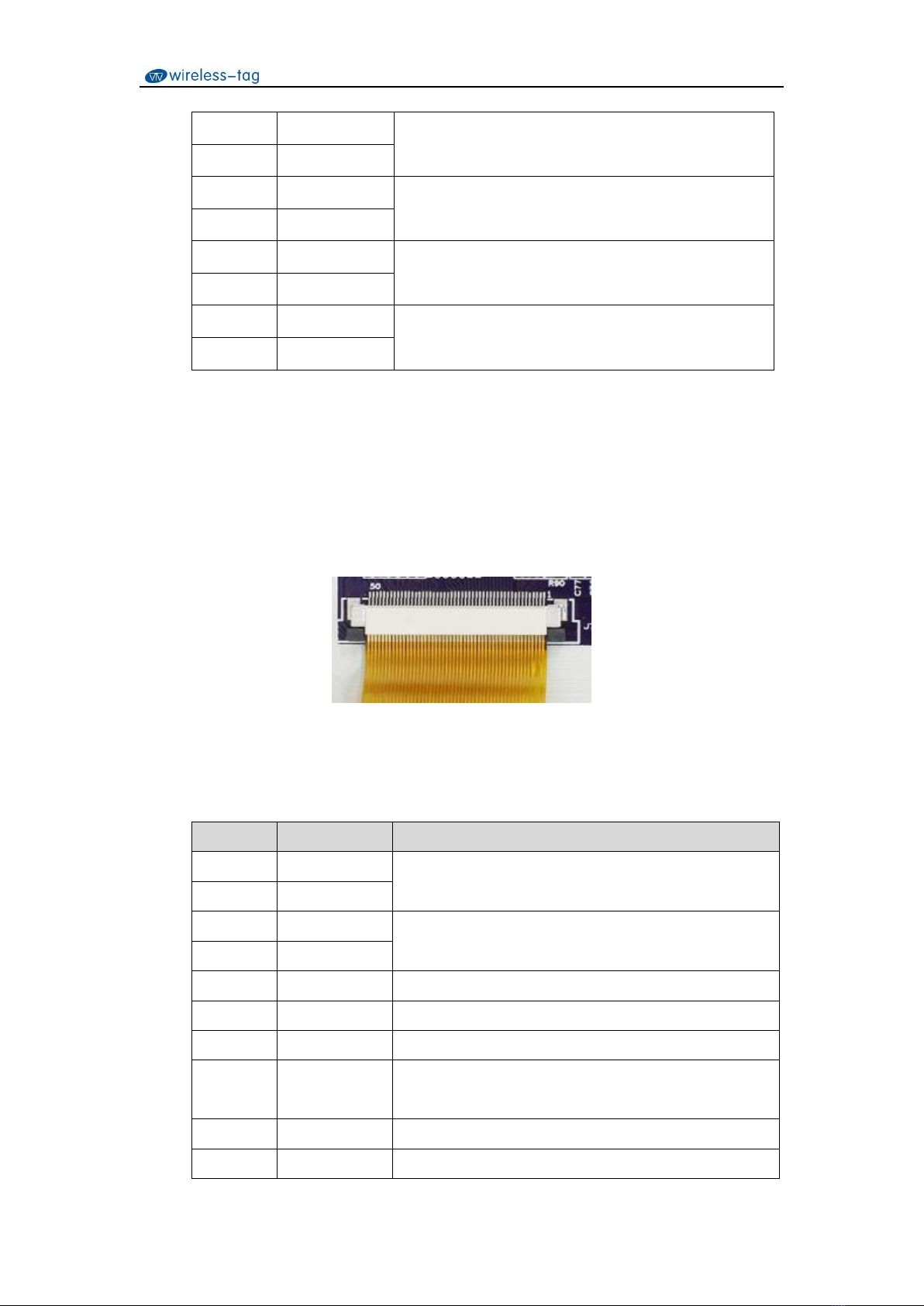
3.5 Speaker Interface..............................................................................................................10
3.6 DMIC Interface................................................................................................................ 10
3.7 AUDIO Interface.............................................................................................................. 11
3.8 TF Card Interface............................................................................................................. 12
3.9 USB Interface...................................................................................................................12
3.10 Ethernet Interface...........................................................................................................12
3.11 WIFI Antenna................................................................................................................. 12
3.12 Debug Serial Interface................................................................................................... 12
3.13 ESP32-WROOM-32U................................................................................................... 13
3.14 Extension Interface(GPIO)....................................................................................... 14