Wisi OT 32 User manual

Operation Manual
OT 32 (Dual-) DVB-Scrambler
044 137

Operation Manual 12./07 WISI Communications GmbH & Co. KG
Index
SAFETY AND INSTALLATION NOTES PLEASE OBSERVE! ............. I
1. Overview
1.1 System Introduction 3
1.2 Function Introduction 3
1.3 Front & rear panel 3
2. Basic configuration of the device
2.1 Configuring a brand new device 5
2.2 Using the scrcmd tool to configure the IP address 5
3. Scrambling configuration (web browser interface)
3.1 Input fields 8
3.2 Status page 9
3.3 Detailed Event Log 10
3.4 ASI / IO Settings Page 10
3.5 ASI / IO Status Page 11
3.6 Misc. Settings Page 12
3.7 ECMG Settings Page 13
3.8 ECMG Status Page 14
3.9 EMMG Settings Page 14
3.10 Detailed EMMG Status Page 15
3.11 EIS Settings Page 16
3.12 Detailed EIS Status Page 17
3.13 Private PSI (CAT/PMT) 17
3.14 Global PID mappings Page 18
3.15 Current PID Mapping page 18
3.16 Service List page 19
3.17 Scrambling Control Group List 21
3.18 Edit (new) SCG Page 23
3.19 Provision a new Scrambling Control Group 25
3.20 Modifying an existing Scrambling Control Group 25
3.21 Deprovision of an existing Scrambling Control Group 26
3.22 Save&Reboot 27
3.23 Default&Reboot 27
3.24 Cancel&Reboot 27
4. Specifications 29
Page 1 of 32

Operation Manual 12./07 WISI Communications GmbH & Co. KG
SAFETY AND INSTALLATION NOTES PLEASE OBSERVE!
Caution
The mains voltage must match the rated input voltage of the unit (180-265 VAC; 50/60
Hz).
Connecting cable — Lay the cable so that no- one can trip over it.
— Lay the cable with a downward loop so that any water condensing on it can drip on
the floor instead of running into the unit.
Selecting the installation location
Excessive temperatures will reduce the operating lifetime of the unit. DO not install the
unit directly above or in the vicinity of radiators or heating systems where it would be
subjected to thermal radiation or oil vapours.
Ventilation slots
Do not cover the ventilation slots.
Moisture
Water dripping or splashing onto the unit will damage it. If there is condensation on the
unit, wait until this has evaporated before switching the unit on.
Caution – danger!
In accordance with EN 50 083-1, the antenna system must comply with the safety
requirements with respect to grounding, potential equalisation, etc.
Service work
Service work may be carried out only by qualified personnel. Always disconnect
the power supply voltage before starting any such work.
1 HE
1 HE
OTxx
OTxx
OTxx
Page 2 of 32

Operation Manual 12./07 WISI Communications GmbH & Co. KG
Page 3 of 32
1. Overview
1.1 System Introduction
OT 32 Scrambler is the equipment that scrambles selected programs of transport
stream (TS) under the control of CAS, allows the only authorized user to receive
and watch the programs. Thereby system operator can realize management of
conditional charge. The equipment implements compatibleness with many CA
systems by adopting universal scrambling arithmetic of DVB standard and data
protocol of TCP standard.
1.2 Function Introduction
OT 32 (Dual-) DVB-Scrambler main functions:
zStand alone Scrambler for DVB transport-stream signals
zScrambling to selected programs or transport stream (SPTS/MPTS)
zInjecting of ECM and EMM from the CAS system into the
transportstream
zCorrected PCR-jitter caused by injecting the EMM/ECM datas
zCompliant with DVB standard CAS systems
zComplicant with DVB Simulcrypt, supporting up to 4 CAS
zEffective input data rate 1-70 Mbps
zPacket length 188 and 204 supported
zInjection of EMM ECM data through Ethernet
zCommon scrambling Algorithm used
zGeneration of scrambling Control Word (CW)
zManaging of PSI/SI information related to CA
zTCP and UDP protocol supported
zConfiguration via Webinterface and command line over TCP/IP
zSNMPv2c network management
zExpandibility to dual-scrambler

Operation Manual 12./07 WISI Communications GmbH & Co. KG
1.3 Front and rear panel
WISI STREAMLINE Scrambler
STATUS POWER
ASI
12345
STATUS ASI
FUSE T2A/250 VAC OFF
ON
P
O
W
E
R
Ethernet ASI
in
67 8
230 VAC
ASI
trough ASI
out 1 ASI
out 2 Ethernet ASI
in
10 11
ASI
trough ASI
out 1 ASI
out 2
9
Figure 2-1 Stand-alone scrambler back panel interface
1,3 ASI interface LEDs 2, 4 STATUS LED
5 POWER LED 6 FUSE T2A/250 VAC
7 POWER ON/OFF. 8,10 100 Base/T.
9,11 ASI Interface
Page 4 of 32

Operation Manual 12./07 WISI Communications GmbH & Co. KG
2. Basic configuration of the device
For general every day administrative purposes the device supports:
• HTML web browser interface
For configuration of a brand new device a proprietary interface called “BCMD” = “broadcast
command” interface is supported. For uploading new firmware and FPGA code, the TFTP
interface is supported.
2.1 Configuring a brand new device
Generally the administrator will assign a fixed IP address to the scrambler. In the default state
of the scrambler, there is no fix IP address defined.
2.2 Using the scrcmd tool to configure the IP address
This chapter describes the proposed method to configure a new device.
Attention: The method requests all scramblers in the network to return their current MAC
address and IP address
However, its not necessary to compute the IP address to configure the scrambler first time.
The scrambler supports a proprietary interface (called “BCMD” interface), that allows
configuration using UDP broadcasts. The scrambler automatically activates the BCMD
interface whenever there’s no fix IP address defined.
The detection and enumeration of scramblers present in the network is done with a command
line utility for Windows and Linux provided with the scrambler:
Enumerate all scramblers.!!
The tool will broadcast messages into the network, requesting all scramblers to return their
current MAC address and IP address
scrcmd -enum
The return will look like this. The example shows two scramblers on the network:
[00] 00:11:22:33::44:55 169.254.1.85
[01] AA:BB:CC:DD::EE:FF 169.254.1.1
Please note: This list will also include devices which already have a fixed IP address assigned,
if the BCMD interface is still enabled.
Set the IP address of a scrambler and reboot it.
Page 5 of 32

Operation Manual 12./07 WISI Communications GmbH & Co. KG
Page 6 of 32
The command reconfigures the IP address of the scrambler identified by the MAC address
00:11[...] to 172.29.0.130.
scrcmd -mac=00:11:22:33:44:55 -ip=172.29.0.130 -mask=255.255.0.0 –reboot
Identify the physical scrambler visually by its MAC address
The command causes the scrambler owning the MAC address 00:11[...] to flash its front panel
LED red/green for some seconds:
scrcmd -mac=00:11:22:33:44:55 –flash

Operation Manual 12./07 WISI Communications GmbH & Co. KG
3. Scrambling configuration (web browser interface)
The HTTP Interface consists of a menu frame on the left hand side and a parameter frame on
the right hand side.
To open the HTML interface, open a web browser and enter the URL (replace 172.29.0.130
by the IP address of your device):
http://172.29.0.130
This will automatically open the “Status View” page shown below. The Status page is the
index page of the HTML interface. It will automatically show if you access the scrambler, or
if you click on Status. This page shows version numbers and an overall description of the
scrambler status. The example below shows the scrambler in an erroneous state, because thereis
no transport stream present on the ASI input connector:
To setup the scrambler you step through almost every menu item (in the menu bar on the left
hand side) from top to bottom and modify the settings according to your DVB headend setup.
When you are done with the setup you click on “Save&Reboot” to store the settings
permanently and restart the scrambler, which will – after the restart - be working as
configured.
Page 7 of 32

Operation Manual 12./07 WISI Communications GmbH & Co. KG
Page 8 of 32
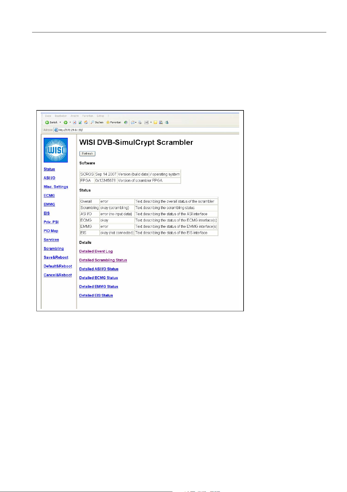
To make modifications to settings, click into the corresponding edit box, alter the value and
then click on the “Submit” button located on the upper left corner of the HTML page. The
scrambler will then process the modifications. It will possibly limit some values
automatically, so they remain in the allowed operating range.
The status pages, like shown above, do not have a “Submit” button, but a button named
“Refresh”. You click on this button, to refresh the contents of the status variables.
The scrambler presents information to the administrator mainly using tables. These tables
either have 3 or 6 columns. The first column contains a short name of the parameter presented
in this row. The last column usually contains a short description of the parameter, it may be
empty, if there is no description available. In between the short parameter name and the
description is the data field, that contains the content of the parameter. Some tables present
only one data column, other present 4 data columns to the administrator.
3.1 Input fields
Each input field has a specific data format:
Numeric input fields: The scrambler accepts both hexadecimal numbers (Starting with “0x”)
and decimal numbers in numeric data fields. Numeric input fields are for example used to
define port numbers. Acceptable numbers are for example:
0x201
513
0xFFFFFF00
The scrambler will present the number in numeric fields either as decimal or as hexadecimal
values, depending on whatever is suitable for this input field. For example: Port numbers are
usually decimal, while the CAS-ID is presented as a hex value. Independent of the preferred
presentation, you can always enter hex. or dec. values in numeric input fields.
IP address input field: The scrambler accepts an IP address in the format “a.b.c.d” here. For
example:
172.29.0.130
Hexadecimal string input fields: The scrambler accepts a string of characters “0…9” and
“A..F” and “a…f” without a leading “0x”. While numeric input fields only accept values, that
fit into 32Bit variables (or less), the hexadecimal string input fields accept a much longer
string of hexadecimal values. The hexadecimal string input fields are (for example) used to
define “access criteria” and private data to be inserted into the CAT (for example). Example:
A076B300005F
String input fields: The scrambler accepts a string of characters. String input fields are for
example used for naming Scrambling Control Groups.
Although many values take effect immediately, some values can only be applied after a reboot
and some will take effect only after a transponder scan.

Operation Manual 12./07 WISI Communications GmbH & Co. KG
3.2 Status Page
The Status page is the index page of the HTML interface. It will automatically show if you
access the scrambler, or if you click on Status in the menu bar on the left hand side. This page
shows version numbers and an overall description of the scrambler status. The example below
shows the scrambler in an erroneous state, because there is no transport stream present on the
ASI input connector:
The Status page contains links that lead to status pages of some functional units of the
scrambler. For example: The ECMG parameter page has its associated ECMG status page.
These detailed status pages are described elsewhere in this document.
The first table on the status page contains the versions of the scrambler software:
· SCROS: Build date of the operating system. The build date is used as the “version
number”.
· FPGA: Version number of the FPGA code.
Page 9 of 32

Operation Manual 12./07 WISI Communications GmbH & Co. KG
3.3 Detailed Event Log
The detailed event log is accessed by clicking on “Status” in the menu bar on the left hand
side and then on the link “Detailed Event Log”. The “Event log” is a table, storing:
· The time when an event occurred
· The severity (INFO = informational, ERROR = error condition)
· The functional unit of the scrambler that caused the event.
· A message describing the event.
The “Detailed Event Log” consists of multiple pages. You navigate this pages by clicking on
“First”, “Previous”, “Next” or “Last”. In the case of the event log, clicking on “First” shows
the oldest, and “Last” the latest events.
3.4 ASI I/O Settings Page
The ASI I/O Settings page lets you configure the data rate and data format of the output
transport stream.
Page 10 of 32

Operation Manual 12./07 WISI Communications GmbH & Co. KG
3.5 ASI I/O Status Page
The ASI I/O Status Pages shows the status of the ASI input and output. The content will be
updated when you press “Refresh”.
• Input data rate: Detected data rate on the ASI input.
• Input packet rate: Number of transport stream packets per second arriving on the
ASI input.
• Input erroneous packet: Number of transport stream packets containing errors per
second arriving on the ASI input.
• Input overflow rate: Number of times, the input fifo of the scrambler overflowed.
• Input null packet rate: Number of null transport stream packets (PID 0x1FFF) per
second arriving on the ASI input.
• Queued (inserted) packet rate: Number of transport stream packets inserted into
the transport stream by the scrambler. This value includes ECM, EMM, PAT, CAT
and PMT transport stream packets being inserted.
• Dropped packet rate: Number of transport stream packets, that the scrambler
removes on the input side. The scrambler drops PAT, CAT and PMT and all packets
arriving on reserved ECM / EMM PID´s.
• Scrambled packet rate: Number of transport stream packets, that were scrambled by
the scrambler per second.
Page 11 of 32

Operation Manual 12./07 WISI Communications GmbH & Co. KG
• Output null packet rate: Number of null packets generated by the scrambler per
second to meet the output data rate.
• Output data rate: The data rate being output on the ASI.
Please note: The “Input null packet rate” has to be bigger than the “Queued (inserted) packet
rate”. If the “Queued (inserted) packet rate” is bigger than the “Input null packet rate” for an
extended amount of time, the resulting output transport stream becomes erroneous.
Also, if the “Output null packet rate” is 0 or very low for extended periods, this also indicates
an scrambler overload.
3.6 Misc. Settings Page
This page lets you setup miscellaneous settings:
• Date/Time: Enter the current date and time here. The format is YYYY-MM-DD
HH:MM:SS. You have to set the current date and time only, if you plan to use
activation times in Scrambling Control Groups.
• Protocol Version: Selects the ECMG protocol to be used (2 or 3).
• Default CP Duration: The scrambler supports different crypto period (CP) durations
for every Scrambling Control Group. If you don’t specify a CP duration for a
Scrambling Control Group, the scrambler will automatically use the value specified
here. The minimum value is 8000 ( = 8 seconds ) crypto period duration.
• Filter CAT: If 0, the scrambler will take the original CAT present in the input
transport stream and append its own CA descriptors. If the value is 1 (nonzero), the
scrambler will ignore the content of the original CAT and generate a new one,
containing only CA descriptors generated by the scrambler.
• Fixed CW: If 0, the scrambler will use random codewords (CW) to scramble the
content. If 1 (nonzero), the scrambler will use a fixed CW as defined below. The value
Page 12 of 32

Operation Manual 12./07 WISI Communications GmbH & Co. KG
1 should only be used for debugging purposes of course!
• 48Bit CW: If 0, the scrambler will use 64 Bit codewords to scramble the content. If 1
(nonzero), the scrambler will use 48Bit codewords. Some CAS only support the 48Bit
mode.
• CW(H): This is the high dword of the fixed codeword to be used, if Fixed CW is 1.
• CW(L): This is the low dword of the fixed codeword to be used, if Fixed CW is 1.
3.7 ECMG Settings Page
The scrambler supports up to 4 different ECMGs in parallel. Depending on your application
you have one up to eight ECMGs attached. If one is connected only, you are running your
system with one CAS and without backup. If you have eight ECMGs attached, you are
running your system with four CAS and one backup for every CAS.
Every of the four columns is used to configure the main and backup IP addresses and ports of
one CAS. If you set the IP address to 0.0.0.0 or the port to 0, you disable the associated CAS.
The CAS-ID and Sub-CAS-ID depend on the CAS you are using in your environment.
The following example shows one CAS with both main and backup ECMGs activated (Row
ECMG-0). All other CAS are disabled. The main ECMG is accessed on port 5000 of
10.0.0.70, the backup ECMG is accessed on port 6000 of 10.0.0.70. Of course its possible to
have different IP addresses for main and backup ECMG.
Page 13 of 32

Operation Manual 12./07 WISI Communications GmbH & Co. KG
3.8 ECMG Status Page
The ECMG Status Page consists of two parts. The upper part lets you verify the connection
and communication between ECMG and the scrambler.
Use the scrollbar of your browser to reach the bottom part of the ECMG Status. The bottom
part informs you about the DVB SimulCrypt parameters that the scrambler and ECMG agreed
on using. See the DVB SimulCrypt specification for a detailed description of the meaning of
each parameter.
3.9 EMMG Settings Page
The scrambler is capable of being connected to four EMMGs. You define the ports to listen to
EMMG requests on this page. For each of the four EMMGs there are two ports to be defined:
• The TCP Port
• The UDP Port
To deactivate an EMMG interface, set the associated TCP Port to 0. The UDP interface does
not work without the TCP interface activated, while the TCP interface is capable of working
alone.
Page 14 of 32

Operation Manual 12./07 WISI Communications GmbH & Co. KG
The example shows a configuration, that lets the scrambler listen on port TCP port 5001 for
EMMG requests, like EMM provisions. It will also accept EMM provisions on UDP port
2003.
The data rate parameter sets the max. amount of data being granted for the EMM data stream.
Please note: The actual amount of data rate available for EMMs and ECMs depends on the
ASI I/O settings. For example: Its possible to grant 1MBit/s EMM rate here, but there is no
chance for the scrambler to pack these EMM packets into a physical transport stream being
attached to the scrambler at the desired rate. It’s the responsibility of the headend
administrator to ensure, that there are enough null packets in the transportstream to meet this
setting here.
3.10 Detailed EMMG Status Page
The “Detailed EMMG Status” Page lets you verify the connection with the EMMG. If there is
an EMMG connected to the scrambler, the “Client” row will show the IP and source-port of
the connected EMMG. “0.0.0.0.0:0” means, that there is no EMMG connected.
The rest of the entries count messages and errors. In the case of an error free connection, you
will see “Messages” and “TCP Data provisions” and / or “UDP Data provisions” increase,
while all other values of a column remain 0 (or do not increase).
Page 15 of 32

Operation Manual 12./07 WISI Communications GmbH & Co. KG
3.11 EIS Settings Page
The EIS is an (external) software component that defines Scrambling Control Groups. It
connects to the scrambler using TCP/IP. The scrambler will listen on the specific port for
message of the EIS. If you want to disable the EIS interface, set the value to 0.
Page 16 of 32

Operation Manual 12./07 WISI Communications GmbH & Co. KG
It is possible to verify the Scrambling Control Groups that were defined by an EIS, by
clicking on “Scrambling” in the menu bar.
3.12 Detailed EIS Status Page
The EIS status page lets you check the communication between the EIS and the scrambler.
3.13 Private PSI (CAT/PMT) Data Page
The scrambler inserts private PSI data into the CA descriptors. Enter the hexadecimal string
of the private PSI data to be inserted into the edit boxes, then press the “Submit” button.
Page 17 of 32

Operation Manual 12./07 WISI Communications GmbH & Co. KG
The content of the CA descriptors of the CAT will change immediately (within 500ms). The
contents of the CA descriptors in a PMT will only change when the corresponding services
switches from clear to scrambled. If you use Save&Reboot after the whole setup, you can be
sure, that your private data will be used.
Please note: There is no need for private PSI data, if your head end conforms to the DVB head
end standard.
ATTENTION! You have to take care by yourself, that the size of the PMT section
containing your private data and all CA descriptors does not exceed the maximum
size when using private data.
3.14 Global PID mappings Page
This page enables the administrator to define PID ranges to be used for placing ECM and
EMM PID´s. The scrambler supports up to 4 ECM generators and up to 256 Scrambling
Control Groups. Therefore the scrambler needs up to 1024 (free) PID´s to be used as ECM
PID´s.
The PID´s will be automatically assigned by the scrambler after a successful scan. The
scrambler tries to allocate the PID´s in the given ranges, taking PIDs into account, that are
already in use. The scrambler analyzes the PAT, CAT and PMT´s during the scanning to find
PID´s, that cannot be used as ECM or EMM PID´s.
3.15 Current PID Mapping Page
3.16 Service List Page
The Service List page lets you scan the services of the transport stream applied to the ASI
Input of the scrambler.
The look of the services page differs, depending on the number of scanned services. If no
services are scanned, then the services page notifies you about it like shown below.
Page 18 of 32

Operation Manual 12./07 WISI Communications GmbH & Co. KG
To scan for services, click on the “Scan” button. During scan the page looks like below. If the
web browser supports timed updates, the page will be update automatically every 5 seconds
and notify you about the scanning progress. If the web browser does not automatically update
the page every 5 seconds, you have to manually click on “Services” link in the menu bar once
about every 5 seconds to update the scanning progress.
If an error occurs you will get the following information when the scan finishes:
Page 19 of 32
Table of contents