WITA HE OEM 2 User manual

HE OEM 2 | 40-XX | 60-XX
INSTALLATION AND
OPERATING INSTRUCTIONS

Manual
HE OEM 2 | 40-XX | 60-XX
Contents
Declaration of conformity ..........................................................................................................
Notes on safety ............................................................................................................................
General ..........................................................................................................................................................
Identification of symbols in the operating instructions.....................................................................
Personnel qualification ............................................................................................................................
Danger of not observing savety instructions ....................................................................................
Safety-conscious work .............................................................................................................................
Safety instructions for the operator .....................................................................................................
Safety instructions for installation and maintenance work ............................................................
Unauthorised conversion and production of spare parts ...............................................................
Unpermitted operation .............................................................................................................................
Transport and storage .................................................................................................................
Intended use .................................................................................................................................
Product information .....................................................................................................................
Technical data HE OEM -XX -XX ..........................................................................................
Delivery range ...........................................................................................................................................
Pump description ....................................................................................................................
Pump settings and capacity .....................................................................................................
Buttons ......................................................................................................................................................
Service mode setting the capacity range ..........................................................................................
Control panel and LED display .............................................................................................................
Selection of the operating mode and degree of work ..................................................................
Recommendations for selecting a degree of work ........................................................................
Automatic night reduction of power...................................................................................................
Filling and venting the installation ..........................................................................................
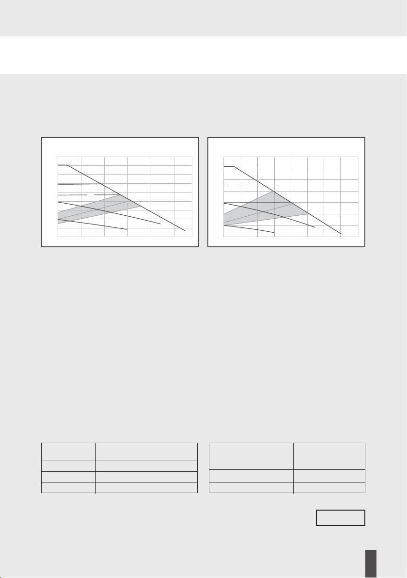
Relationship between pump setting and capacity ................................................................
Capacity characteristics.............................................................................................................
Installation ..................................................................................................................................
Electrical connection .................................................................................................................
Maintenanceservice .................................................................................................................
Malfunctions causes and elimination .....................................................................................
Disposal .......................................................................................................................................
2

Display HE Pumpen
Manual
HE OEM 2 | 40-XX | 60-XX
3
EU DECLARATION OF CONFORMITY
Subject of the declaration Heat circulation pump
Type HE OEM
Design -xx -xx
We declare with sole responsibility that the products specified above to which this EC
Declaration of Conformity refers fulfil the following standards and guidelines
Electromagnetic Compatibility Directive EU
EN - A A
EN - A A
EN --
EN --
Low Voltage Guideline EU
Guideline for Energy-Consuming Products EG
Eco-design requirements and
EN -
EN -
EN -
EN -- A A
RoHS EU
This declaration is submitted for and on behalf of the manufacturer by:

Manual
HE OEM 2 | 40-XX | 60-XX
2 Safety Instructions
2.1 General
These installation and operating instructions are a part of the
product, and contain basic information that must be observed
during installation, operation and maintenance. For this reason,
the installer and specialist personnel or operators must read
these instructions prior to set-up.
Please observe both the general safety instructions listed
under section 2 and the special safety instructions detailed in
the other sections.
A copy of the EC Declaration of Conformity is provided with
these instructions. This declaration shall be deemed void in the
event of a modification that has not been agreed with us.
2.2 Identification of notes in the operating instructions
General hazard symbol
Warning! Danger of personal injury!
Observe the relevant accident
prevention regulations.
Warning! Danger from electrical
voltage! Prevent hazards arising from
electrical energy. Observe
the instructions in local or general
regulations (e.g. IEC, VDE, etc.), and
those of the local energy supplier.
4

Manual
HE OEM 2 | 40-XX | 60-XX
This symbol indicates useful information
for handling the product. It indicates
potential diculties and aims to ensure
safe operation.
Signs attached directly on the product, such as:
• direction of rotation arrow
• type plate
• identification of connections must be strictly observed and
kept in an easily legible state.
2.3 Personnel qualification
The personnel used for mounting, operation and maintenance
must have relevant qualifications. Areas of responsibility and
monitoring of personnel must be guaranteed by the
owner/operator. If personnel do not have the necessary
know-how, they must be trained or instructed
accordingly. This device can be used by children at or above
the age of 8 years, as well as by persons with reduced physical,
sensory or mental capabilities, or who lack experience and
knowledge, if they are supervised or have been instructed
concerning the safe use of the device and if they understand
the hazards arising from its use. Children may not play with the
device. Cleaning and maintenance operations may not be
carried out by children without supervision.
5
Advice

Manual
HE OEM 2 | 40-XX | 60-XX
2.4 Danger of not observing safety instructions
Not observing the safety information can endanger persons,
the environment and the system. Not observing the safety
instructions shall result in the loss of any and all claims to
warranty.
Potential dangers include:
• Hazards to persons through electrical and mechanical eects.
• Failure of important system functions.
• Hazard to the environment from escaping fluids resulting
from a leak.
• Failure of prescribed repair and maintenance work.
2.5 Safety-conscious working
Observe the safety instructions detailed in this manual, along
with the current national accident prevention regulations.
Should the system operator also have their own internal
regulations, these must also be observed.
2.6 Safety instructions for the operator
• Any existing touch guard protecting moving parts may be
neither removed nor shut down while the system is in
operation.
• In the event of a fluid leak, any fluids must be collected or
diverted in a way that prevents hazards to persons and the
environment from arising.
6

Display HE Pumpen
Manual
HE OEM 2 | 40-XX | 60-XX
• Prevent hazards arising from electrical energy.
• Observe the instructions in local or general
regulations (e.g. IEC, VDE, etc.), and those of the
local energy supplier.
• In the event of hazards arising from the system due to
contact with hot or cold parts, these parts must be fitted
with a touch guard.
• Keep flammable substances away from the product.
2.7 Safety instructions for installation and maintenance work
The system operator is responsible for ensuring that all
installation and maintenance work is carried out by qualified
personnel. These persons must also have familiarised
themselves in advance with the product using the operating
instructions. Conducting work on the pump is only permitted
when the system is shut down.
Ensure that the device is securely disconnected from the
power supply. Disconnect the device plug to achieve this.
Prescribed instructions for shutting down the device can be
found in the operating instructions. All protective mechanisms,
such as a touch guard, must be correctly reattached after work.
2.8 Unauthorised conversion and production of spare parts
Modification or conversion of the product is only permitted
after prior consultation with the manufacturer. Only use
original spare parts for repairs. Only use accessories that have
7

Manual
HE OEM 2 | 40-XX | 60-XX
been approved by the manufacturer. The manufacturer shall
bear no liability for any consequences resulting from the use of
other parts.
2.9 Unpermitted operation
If the pump is disconnected from the power supply, wait at
least 1 minute before reactivating. Otherwise, the pump's
inrush current limit has no eect, which can lead to functional
errors or damage to any connected heating controller. The
pump's operational safety can only be ensured
if it is used as intended. Please observe section 4 of
these operating instructions here. Ensure compliance
with the limit values detailed in the technical data.
3 Transport and Storage
After receiving the product, inspect it immediately for damage caused in transport. Should you
detect any transport damage, assert a claim with the haulier.
Incorrect transport and storage can lead to personal injury or damage to the product.
• Protect the product against frost, moisture and damage during transport
and storage.
• Only carry the pump by the pump housing, and never by the connection cable
or terminal box.
• If the packaging weakens due to moisture, this can lead to the pump falling
out and causing severe injury
Intended use
These high eciency pumps are designed to circulate hot water in central heating
systems and are also suitable for pumping low density liquids in industrial and
commercial applications They are also suitable for solar installations
8

Manual
HE OEM 2 | 40-XX | 60-XX
Product information
Technical data -XX -XX
-XX -XX
Maximum elevation height m m
Maximum flow rate lh lh
Power consumption P (W) - -
Supply voltage x V Hz
Sound pressure level dB(A)
EEI ≤ 0.20
Protection type IP
Temperature class TF
Ambient temperature C to C
Medium temperature to C
System pressure Max bar (MPa)
Permitted media heating water acc to VDI
Waterglycol mixture
Supply pressure Acceptable range of application
Attention!
The use of unsuitable media can destroy the pump and injure you
It is necessary to observe the manufacturer’s information and safety data sheets!
9
Medium Minimum
temperature supply pressure
< 75 °C 0.05 bar 0.005 MPa 0.5 m
75 °C - 90 °C 0.3 bar 0.03 MPa 3.0 m
90 °C - 110 °C 1.1 bar 0.11 MPa 11.0 m
Temperature range at Permissible
maximum medium
ambient temperature temperature
25 °C 5 °C to 110 °C
40 °C 5 °C to 95 °C
Advice
Characteristic HE OEM 2 | 40-XX
H
(m)
4
3.5
3
2.5
2
1.5
1
0.5
0
0 0.5 1 1.5 2 2.5 Qm3
/h
AUTO
CPII
CPI
PPI
PPII
SI
SII SIII
Characteristic HE OEM 2 | 60-XX
H
(m)
6
5
4
3
2
1
0
0 0.5 1 1.5 2 2.5 3 3.5 Qm3
/h
AUTO
CPII
CPI
PPI
PPII
SI
SII
SIII

Manual
HE OEM 2 | 40-XX | 60-XX
Delivery range
• Original assembly and operating manuals
• Pump
• flat gaskets
• Pump plug
• Insulation
Pump descritption
In an average household to of electricity consumption is used by conventional standard
pumps Together with the HE OEM pump series we have developed a circulation pump with
an energy eciency index ≤ By using HE OEM energy consumption can be reduced by
up to approx compared to a conventional circulation pump The hydraulic capacity can be
kept almost the same as with the standard pumps The pump capacity adapts to the actual sys-
tem demand as it works according to the proportional pressure method
Pump settings and flow capacity
Description of the operating elements
Buttons
All pump functions can be controlled with just two buttons The button switches the night
reduction function on and o The button controls the operating modes The selected ope-
rating mode is shown in the clear field of the LED indicator
10

Manual
HE OEM 2 | 40-XX | 60-XX
Service mode setting the capacity range
The capacity range can be changed to m or m in service mode
• The pump must be disconnected from the V
mains voltage for at least seconds
• Connect the pump to the V mains voltage
• Press the and buttons simultaneously
within seconds
• Then release both buttons
• Select the capacity range with the buton
• - m
• - m
• The pump must be disconnected from the V
mains voltage for at least seconds
• Connect the pump to the V mains voltage
The setting process is now complete The pump is now running in the selected capacity range
If necessary the pump setting can be readjusted at any time
Control panel and LED display
Display of energy consumption in watts
Automatic night reduction display
button for activating the automatic night reduction
operating mode selection button
Display for activated AUTO Smartadapt mode
Display of the nine operating levels (characteristics) of
the pump
11
1
6
4
3
2
5

Manual
HE OEM 2 | 40-XX | 60-XX
12
Selection of the operating mode and degree of work
Constant speed adjustment I II i III
In this operating mode the pump runs at a constant rotational speed over the entire
characteristic curve
Constant pressure adjustment CP CP
In this type of adjustment the pressure generated by the pump is kept at a constant level
This type of adjustment is especially suitable for use in underfloor heating systems
Proportional pressure adjustment PP PP
The pump is controlled by the proportional pressure method In this case the pressure
generated by the pump is adapted to the changing flow rate This operating mode is
especially useful when the pump is to be used as a circulation pump for heating
Smartadapt
The Smartadapt AUTO function is designed for two-circuit heating systems and underfloor
heating systems The pump capacity is automatically adjusted to the actual heat demand of
the installation The pump power is adjusted gradually and may take more than a week If the
power supply to the pump is interrupted the pump remembers the last setting and resumes
adjusting as soon as power is restored
Upon delivery the pump is set to the AUTO Smartadapt operating level Multiple brief pressing
the select button will continuously toggle between the constant speed constant pressure pro-
portional pressure and AUTO Smartadapt modes
The selected operating mode is indicated by the appropriate LED with characteristic symbols
Number of
button presses
0
1
2
3
4
5
6
7
8
Display
AUTO
(sellected on supply)
PP1
PP2
CP1
CP2
I
II
III
AUTO
Symbol Display
+
+
+
+
+
+
+
Description
AUTO Smartadapt
Min. proportional pressure adjustment
Average proportional pressure adjustment
Min. constant pressure adjustment
Average constant pressure adjustment
Constant speed adjustment I
Constant speed adjustment II
Constant speed adjustment III
AUTO Smartadapt

AUTO CP
Manual
HE OEM 2 | 40-XX | 60-XX
Automatic night reduction display
Display of means that automatic night reduction is activated
Button for activating automatic night reduction
• By pressing the buton in section automatic night reduction is switched on or o
• When the automatic night reduction is activated the symbol lights up in the display
field
The Automatic Night Reduction function is not available in the constant speed levels
Selection of the degree of work
• Pressing the button switches between the operating levels
• The factory configuration of Auto Smartadapt will be re-established by pressing
the button ten times
Recommendations for selecting a degree of work
Factory configuration AUTO Smartadapt
13
Other possible
settings
Optimal
setting
AutoUnderfloor heating CP
CP
AUTO PP
PP
Auto
PP
Two-line systems
Single system
PP
PP

Manual
HE OEM 2 | 40-XX | 60-XX
Automatic night reduction
Conditions for automatic night reduction:
Pumps installed in gas boilers with low water capacity must never be set
to automatic night reduction:
If the heating system does not supply enough heat to the radiators, check whether
the automatic night reduction function is active. If necessary, deactivate the automatic
night reduction function.
To ensure that night reduction functions properly, the following requirements must be met:
1. The pump must be installed on the supply
2. The heating system must be equipped with automatic temperature adjustment on the supply.
How automatic night reduction works
Press the button to activate the night reduction function. If the adjacent
highlighted field is lit, the night reduction is activated and the pump automatically switches
between normal operation and night reduction. Swiching depends on the flow temperature.
The pump automatically switches to night temperature reduction if the flow temperature
drops by more than 10°-15°C in 1 hour.
Switching to normal operating mode takes place immediately as soon as the
flow temperature rises again by 3°C.
14
Advice

Manual
HE OEM 2 | 40-XX | 60-XX
Filling and venting the installation
Fill and vent the installation properly To vent the pump the electronics
should be set to level III and operated in this position for at least minutes
Caution After this procedure you can set the pump to the desired control mode
Incomplete venting will cause noise in the pump and system
Warning! Danger of burns!
Depending on the operating status of the installation
the entire pump can become very hot
15
Advice

Manual
HE OEM 2 | 40-XX | 60-XX
Relation between pump setting and capacity
The characteristic curves show the relationship between pump settings and pump capacity
Capacity characteristics
16
PP1
AUTO
PP2
CP2
CP1
III
III
II
II
I
IS3
1
2
2
1
S2
S1
HE OEM 2 40-XX
H
(m)
4
3.5
3
2.5
2
1.5
1
0.5
0
0 0.5 1 1.5 2 2.5 Qm3
/h
AUTO
CPII
CPI
PPI
PPII
SI
SII SIII
HE OEM 2 60-XX
H
(m)
6
5
4
3
2
1
0
0 0.5 1 1.5 2 2.5 3 3.5 Qm3
/h
AUTO
CPII
CPI
PPI
PPII
SI
SII
SIII

HE OEM 2 | 40-XX | 60-XX
17
Manual
11 Assembly
Correct installation position of the engine
A voltage-free installation must be carried out with the pump motor in a horizontal position
(the direction arrow on the pump body shows the direction of flow). When performing thermal
insulation, make sure that the pump engine and the electronics body are not insulated. If the
installation position is to be changed, the engine case must be rotated as follows.
• Loosen the hexagon socket screws
• Rotate the engine case
• Rescrew and tighten the hexagon socket screws.

Manual
18
System dimensions
Dimensional sketch and dimension table
HE OEM 2 | 40-XX | 60-XX
G
H (mm) H1 (mm) L (mm) B (mm) G (") Weight kg Current (A) Elevation
(without cable) height (m)
40/60 20-130 138 112 130 93 1" 1,94 0,04~0,25/0,04~0,31 0~4/0~6
40/60 25-130 138 112 130 93 1 ½" 2,12 0,04~0,25/0,04~0,31 0~4/0~6
40/60 25-180 138 112 180 93 1 ½" 2,27 0,04~0,25/0,04~0.31 0~4/0~6
40/60 32-180 142 112 180 93 2" 2,46 0,04~0,25/0,04~0,31 0~4/0~6
DimensionsPump
type
Technical data

Manual
19
HE OEM 2 | 40-XX | 60-XX
12 Electrical connection
Connect the power cord to the pump as shown in the picture.
Caution mains voltage! Always observe the necessary safety measures,
VDE regulations and local regulations.
The cross-section of the cable must not be less than 0.75 mm2.
When using cables with fine wires, use end wires sleeves.
Caution Danger to life!
Incorrect installation and incorrect electrical connection can be life-threatening.
Electricity hazards must be ruled out.
• Installation and electrical connection may only be performed by qualified personnel
and in accordance with the applicable regulations (e.g. IEC, VDE, etc.)!
• The type of current and voltage must comply with the data on the rating plate.
• Comply with the regulations of the local power supply company!
• Comply with the accident prevention regulations!
• Never pull on the power cord
• Do not bend the cord
• Do not place any objects on the cord
• When the pump is used in systems with temperatures above 90°C, a
connection cable that is suitably resistant to high temperature must be used
• There is a risk of sharp and jaged edges during assembly.
• Never transport by holding the power cord.
• There is a risk of injury from dropping the pump.
Click
1
2
3
4

Manual
HE OEM 2 | 40-XX | 60-XX
20
13 Maintenance/service
Before carrying out maintenance, cleaning and repair work, disconnect the system
from the power supply and secure it against being switched on again by
unauthorized persons.
At high water temperatures and system pressures, wait for the pump
to cool down beforehand. There is a risk of burns!
14 Malfunctions, causes and elimination
Maintenance work or repair attempts may only be performed by qualified personnel. Before car-
rying out maintenance, cleaning and repair work, disconnect the system from the power supply
and secure it against being switched on again by unauthorized persons. At high water tempera-
tures and system pressures, wait for the pump to cool down beforehand. There is a risk of burns!
Malfunction designation
or pump error code
The pump does not work,
the display does not light up
The pump works but
delivers no water
Noise in the system
The pump is making noise
The building does not heat
up
No automatic power
adjustment in proportional
pressure levels
Possible cause
Power error
Air in the system
The valve is closed
There is air in the system
Pump capacity is too high
Air in the pump
System pressure is too low
Defective expansion vessel
Incorrect pump setting
Night reduction can be
switched on
An open overflow valve in-
stalled in the system makes it
impossible to control
Remediation solution
Check the supply voltage at the pump. If necessary,
switch the circuit breaker back on.
Vent the pump (see chapter 8 in the manual).
Open the gate valve
Vent the system
Check pump settings
Vent the pump (see chapter 8 in the manual).
Increase the pressure on the supply
Check the amount of gas in the expansion vessel
Increase the setpoint (see chapter 7.3 in the manual)
Switch o night reduction
Remove or close the overflow valve, if possible.
This manual suits for next models
10
Table of contents
Other WITA Heat Pump manuals
Popular Heat Pump manuals by other brands

Nortek
Nortek T4BE installation instructions

AERMEC
AERMEC WWM Series Installation and maintenance manual

Nibe
Nibe F2300 user manual

IVT
IVT Optima 600 installation guide

STIEBEL ELTRON
STIEBEL ELTRON HPA-O 4 CS Plus Operation and installation instruction

Magic-Pak
Magic-Pak V Series installation instructions

Daikin
Daikin ALTHERMA User reference guide

Mars
Mars Comfort-Aire Century HEW Series Installation operation & maintenance

Carrier
Carrier 50HX Guide manual

Nordic
Nordic RS Series Installation and service manual

Lennox EMEA
Lennox EMEA eCOMFORT2 Installation, operating and maintenance

Emicon
Emicon R-PAE Use and maintenance manual