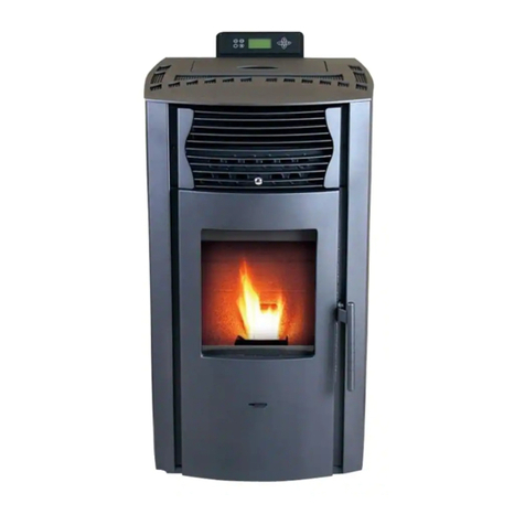
wodtke CW 21 Airplus PO 04.7 E User manual

wodtke
Pellet Stove
Technology
Operating Manual for
S4 Electronic Controlled Stoves
for Software S4 002 and Higher
Thank you for buying a wodtke pellet stove. Please read this
manual before installing and putting your stove into operation! This
will help you to avoid damage that can occur from improper
installation or operation and your stove will be a source of comfort
and enjoyment for you and a boon for the environment for a long
time to come.
We hope your pellet stove gives you many hours of warm, snug
comfort in your home.
Your wodtke GmbH
wodtke

Bedienungsanleitung Steuerung S4_2006_09_25-neu.doc Page 2 / 83
© wodtke GmbH Tübingen. All rights reserved. Subject to change without notice. Month of issue xx/2007 Art. No. 950 281
Table of Contents
1Important General Information ..........................................................................................4
2System Requirements........................................................................................................5
2.1 Application scope and limits ..........................................................................................5
2.2 Minimum room sizes......................................................................................................6
2.3 Minimum operating time / External controller settings ...................................................7
2.4 Heat delivery to water with Waterplus appliances..........................................................7
2.5 Room and ambient temperature and humidity during operation....................................7
2.6 Connection to chimney..................................................................................................7
2.7 Combustion air supply...................................................................................................8
2.8 Pellet quality..................................................................................................................8
2.9 How to increase return flow temperature in Waterplus appliances................................8
2.10 Cleaning, care and servicing .........................................................................................8
2.11 Mains voltage / Power supply........................................................................................8
3Hardware and Functional Description ..............................................................................9
3.1 Type plate and serial number........................................................................................9
3.2 Scope of delivery...........................................................................................................9
4Functional Description.....................................................................................................10
5Operation...........................................................................................................................13
5.1 User levels...................................................................................................................13
5.2 Manual selection of thermal output..............................................................................14
5.3 Initial operation ............................................................................................................14
5.3.1 Special notes on the initial operation of Waterplus appliances.............................15
5.3.2 Filling the fuel hopper...........................................................................................15
5.3.3 External feed systems..........................................................................................15
5.4 Preparations / Lighting the stove .................................................................................16
5.5 Emergency operation with igniters...............................................................................16
5.6 Appliance types and programmes ...............................................................................17
5.7 Operating states & functional messages .....................................................................17
5.7.1 Overview of functional messages (normal operation)...........................................17
5.8 Manual operation / appliance switched off via I/O key.................................................17
5.8.1 Switching the appliance on via the I/O key...........................................................18
5.8.2 Switching the appliance off via the I/O key...........................................................18
5.8.3 Reset via the I/O key............................................................................................18
5.9 Automatic operation “HE OFF” ....................................................................................19
5.9.1 Switching the appliance on via an external controller...........................................19
5.9.2 Switching the appliance off via an external controller...........................................19
5.10 Automatic operation “TW OFF” (only for Waterplus appliances) .................................20
5.10.1 Switching on and off via “TW OFF”.......................................................................20
5.11 Preheating programme “A” ..........................................................................................20
5.12 Heating programme “H” (normal operation).................................................................21
5.12.1 Heating programme when thermal output is set manually....................................21
5.12.2 Modulation heating programme via external controller (2-stage)..........................22
5.12.3 Modulation heating programme via internal controller (safety function)................22
5.12.4 Modulation heating programme via external controller (continuous controller).....23
5.13 Cleaning Programme “R”.............................................................................................24
5.14 Fan after-run “G OFF”..................................................................................................24
5.15 Service prompt “WA” ...................................................................................................25
6Menu Level / Sampling of Functional Values .................................................................27
6.1 Output of On/Off signals or collective error messages (relay table).............................29
7Error Analysis, Error Codes, Safety Functions and Safety Devices ............................30
7.1 Overview of class 1 errors & error codes (safety-relevant)..........................................30
Bedienungsanleitung Steuerung S4_2006_09_25-neu.doc Page 3 / 83
© wodtke GmbH Tübingen. All rights reserved. Subject to change without notice. Month of issue xx/2007 Art. No. 950 281
7.2 Overview of class 2 errors & error codes (not safety-relevant)....................................33
7.3 Internal control functions “H.M” and “TW OFF”............................................................34
7.4 Burn-back protection....................................................................................................34
7.5 wodtke air flow sensor technology...............................................................................34
7.6 Temperature sensor at pellet chute (TP).....................................................................35
7.7 Temperature sensor at flue gas fan (TR).....................................................................35
7.8 Temperature cutoff (STB) + main fuse ........................................................................35
8Cleaning and Care ............................................................................................................36
8.1 Inspecting and removing the ash from the burner pot..................................................36
8.2 Cleaning the burner pot, the pot holder and the ashpit................................................37
8.3 Cleaning the viewing window.......................................................................................38
8.4 Cleaning the surfaces..................................................................................................38
9Servicing............................................................................................................................39
9.1 Cleaning the flueways on Airplus appliance “CW 21”..................................................41
9.2 Cleaning the flueways on Airplus appliance “Smart”....................................................44
9.3 Cleaning the flueways on Airplus appliance “PE” ........................................................47
9.4 Cleaning the flueways on Airplus appliance “Frank”....................................................50
9.5 Cleaning the flueways on Airplus appliance “Topline” .................................................53
9.6 Cleaning the flueways on Waterplus appliance “CW 21”.............................................55
9.7 Cleaning the flueways on Waterplus appliance “Smart” ..............................................58
9.8 Cleaning the flueways on Waterplus appliance “PE”...................................................61
9.9 Cleaning the flueways on Waterplus appliance “Topline”............................................64
9.10 Cleaning the flue gas fan and flue gas connector (all models) ....................................67
9.11 Inspecting the suction pipe and air flow sensor (all models)........................................68
9.11.1 Dismounting and cleaning the air flow sensor and suction pipe ...........................69
9.12 Inspecting and cleaning electrical components (all models)........................................72
9.13 Inspecting and cleaning convection air ducts (all models)...........................................72
9.14 Inspecting and cleaning the pellet chute and temperature sensor TP (all models)......72
9.15 Finishing servicing work, test run, and service reset (all models)................................72
10 Fire Protection Regulations.............................................................................................73
10.1 Furniture and household equipment in the heat radiation area....................................73
10.2 Furniture and household equipment outside the heat radiation area...........................73
10.3 Floor beneath and in front of the stove........................................................................74
10.4 Objects near air inlets and outlets................................................................................74
10.5 Distances from the flue gas connector.........................................................................74
11 Approved Fuels.................................................................................................................75
11.1 Storing pellets..............................................................................................................75
11.2 Heating with wood pellets is good for the environment................................................75
12 Technical Data ..................................................................................................................76
13 EC Declaration of Conformity..........................................................................................77
14 Dimensioned Drawings....................................................................................................78
15 Warranty and Guarantee..................................................................................................81
16 Customer Service / Spare Parts ......................................................................................82
17 Your Local Dealer .............................................................................................................82

Bedienungsanleitung Steuerung S4_2006_09_25-neu.doc Page 4 / 83
© wodtke GmbH Tübingen. All rights reserved. Subject to change without notice. Month of issue xx/2007 Art. No. 950 281
1 Important General Information
Please read all attached instructions and information carefully before installing
your stove and putting it into operation. In this way you will avoid operating
errors and malfunction. The installer and the user must inform themselves
sufficiently through the instruction manuals before putting the stove into operation.
Please observe the relevant local technical codes and regulations (for ex. state
building regulations, fireplace regulations, heating and ventilation technical
code, electrical/VDE guidelines etc).
In Germany the appliance may only be put into operation when the district
master chimneysweep has issued an operating licence. Inform him in good time if
you are planning to install or change a fireplace.
The pellet stove’s intended use is described below. Any other use will be deemed
improper. wodtke will assume no liability for any damage resulting from such improper use.
Operating the pellet according to its intended use also means complying with the operating and
assembly instructions. Any inadmissible manipulation or change to the appliance voids all
warranty and guarantee claims.
All work on this stove, including installation, assembly, initial operation, servicing and
repairs, should only be carried out by a duly qualified company (heating or air heating
installers). Improper work performed on this stove voids all warranty and guarantee claims.
Electrical devices may only be assembled and connected to the mains by a duly qualified
electrician. Electronic components such as circuit boards, air flow sensors and the operating
panel are sensitive to electrostatic charge.
As part of the final acceptance procedure the installing company must instruct the user in a
detailed and competent manner on the stove’s operation, cleaning and servicing. The company
must in particular inform the user on the use of suitable fuel, the need for regular cleaning by
the user, the need for servicing and the safety instructions. Any disregard of the attached
instructions, in particular of the need for regular cleaning and servicing, voids all warranty and
guarantee claims.
Before putting the stove into operation make absolutely sure that all accessories have been
taken out of the firebox and ashpit and the fuel hopper is free of residues (for ex. rubbish,
screws…).
The appliance must regularly be cleaned by the user.
For the servicing of the appliance we recommend that the user make a service contract with
his dealer. If he is sufficiently skilled himself and has been instructed in due detail by the
installing company the user may also undertake the regular servicing himself.
Pull the plug before performing any work on the stove! The mains plug and its
socket must be easily accessible at all times. It is forbidden to operate the appliance
if the power cable is damaged. A damaged power cable must immediately be
replaced by a duly qualified craftsman to prevent hazards.
Do not pull the mains plug while the stove is in operation!
First switch off the stove and wait until the fan after-run time
is over (G OFF).
By adhering to the proper use, operation, care and servicing of your wodtke products
you will enhance their value stability and service life, help to conserve valuable
resources and go easy on the environment as well as your purse.

Bedienungsanleitung Steuerung S4_2006_09_25-neu.doc Page 5 / 83
© wodtke GmbH Tübingen. All rights reserved. Subject to change without notice. Month of issue xx/2007 Art. No. 950 281
2 System Requirements
Appliances from wodtke are always connected in some way to other domestic installations or
products and therefore, like all technical products, they have certain system requirements that
must be met to ensure trouble-free operation. The following sections specify some of most
important requirements, which is to say that they do not necessarily name all requirements.
Please observe all instructions and information, as already stated in the introduction. It is always
advisable to have the installation of a pellet stove planned thoroughly in advance by a qualified
company to ensure that the system components work properly together and the intended overall
solution is achieved. wodtke provides a wide range of compatible accessories for this purpose.
2.1 Application scope and limits
Airplus appliances:
•Single-room heater (warm air heater serving the room of installation or several rooms)
o
Capacity range 2-6 kW: maximum energy output = 9,000 kWh per year at 1500 full load
operating hours at 6 kW.
o
Capacity range 2-8 kW: maximum energy output = 12,000 kWh per year at 1500 full load
operating hours at 8 kW.
Waterplus appliances (capacity range 2- 10 kW):
•Auxiliary heater in addition to existing ones (auxiliary room heating and domestic water
heating)
•Single-storey heater without domestic water heating (domestic water heated separately)
•Whole-house heater in combination with other heat generators
Waterplus appliances should always be planned with particular care, since they not only
produce heating water but through heat irradiation and convection also heat up the room of
installation itself. Please observe the following in this regard.
A Waterplus pellet stove alone is not sufficient as a hot drinking water supply because it
would also heat up the room of installation when used for heating drinking water in the summer.
For this purpose a combination with solar thermal energy or other heat generators (for ex.
electric, oil, gas) is required and, in fact, the ideal solution.
Before opting for a specific model it is always necessary to determine on the basis of the
standard calculation rules the heat demand and from this the heating capacity required for the
room / flat / house in question. Confer DIN EN 12831 (design heat load of buildings) on this
point.
When a pellet stove is to be used for whole-house heating the energy demand for heating
drinking and domestic water must be considered in addition to the pure room heating
demand. Another point to bear in mind is that heating a new building can require more than
20% additional energy during the drying phase (approx. 0.5 to 1year) in some cases.
If the temperature is to be set low at night and there is a high demand for hot domestic water
(shower water) in the morning, it must be ensured that the stove has sufficient heating
capacity to meet peak demand. This can be achieved, for ex., by means of a sufficiently
dimensioned buffer storage in combination with other heat generators (electric immersion
heater, oil or gas boiler for reserve capacity).
Please also note that the heating demand of a house is influenced to a large degree by its
occupants’ heating habits and can thus turn out higher than calculated (for ex. due to high room
temperatures, frequent airing, tilted windows etc.).

Bedienungsanleitung Steuerung S4_2006_09_25-neu.doc Page 6 / 83
© wodtke GmbH Tübingen. All rights reserved. Subject to change without notice. Month of issue xx/2007 Art. No. 950 281
As a practical guide value, the largest of our Waterplus appliances (10 kW nominal heating
capacity) is capable of generating a maximum 15,000 kWh per year. This is equivalent to 1500
full load operating hours without interruption at a thermal output of 10 kW. Note that when
delivered by an appliance of our “Topline” series, 40% (= 6,000 kWh) of this thermal output
would go towards heating the room of installation, while with an appliance of our series “Smart”
“PE” or “CW 21” the share of heat delivered to the room of installation would be around 20%,
i.e. 3,000 kWh. This must be taken into account in the planning phase by ensuring that
the room of installation is sufficiently large. The following section contains recommendations
for minimum room sizes and suggestions for alternative solutions for smaller rooms of
installation.
2.2 Minimum room sizes
For all wodtke pellet stoves, the room of installation should at minimum have a floor area of 10
m² and a room volume of 15 m³. With Waterplus appliances one must also take into account
that the room of installation is additionally heated through heat radiation and convection. The
following guide values apply in this case:
•Topline Waterplus appliances (60% of thermal output delivered to water*):
room of installation should account for at least 50% of total heated floor area
•Smart / PE / CW 21 Waterplus appliances (80% of thermal output delivered to water*):
room of installation should account for at least 30% of total heated floor area
If the room of installation is too small or the hot water demand to high, the room of installation
will become overheated.
Heating surfaces in the room of installation of a Waterplus appliance: If solar energy
plants or buffer storages are used for auxiliary heating, then the room of installation of the
Waterplus appliance must have additional heating surfaces (radiator, floor heating) so that it can
be heated even when operation of the boiler is not required. This can be the case in
interseasonal periods, for example: In autumn the solar plant delivers sufficient energy to
charge up buffer storage completely. The pellet stove boiler can then remain switched off
because the room of installation can be heated via a radiator using energy from the buffer
storage. This would not be possible without a radiator in the room of installation.
Proposed solution when installing Waterplus appliances in small rooms: If you have opted
for a Waterplus device and the designated room of installation does not meet the above
requirements, you can use a clock or room thermostat that
pellet stove boiler
radiator
heating circuit
chimney
Schematic drawing without buffer storage, control and hydraulic
equipment, installations room etc.
*nominal thermal output rating given in accordance with DIN 18891 (draft to DIN 18894)
room or interconnected rooms
of installation)

Bedienungsanleitung Steuerung S4_2006_09_25-neu.doc Page 7 / 83
© wodtke GmbH Tübingen. All rights reserved. Subject to change without notice. Month of issue xx/2007 Art. No. 950 281
switches the Waterplus appliance off as soon as the set maximum room temperature has been
reached. This will reliably prevent the room of installation from overheating. In this case the
energy needed for the other rooms or for heating drinking water must be generated from
additional heat sources. This is usually achieved by means of a cascade connection with an
electric immersion heater or a oil or gas boiler. Then the auxiliary heat generator only starts up
automatically when the boiler of the Waterplus appliance is switched off. This means that the
base load is still borne by the boiler of the Waterplus appliance, while the other heat generators
only serve to meet demand peaks.
2.3 Minimum operating time / External controller settings
Pellets are a solid fuel which inherently require more time to ignite than do liquid or gaseous
fuels.After the start of ignition it can take a few minutes for the first flame to appear, and a total
of 15 minutes before the preheating programme is completed and the appliance has reached
its full thermal output.In contrast to oil or gas fuelled stoves it can also take a few minutes
after switching off the appliance until all the pellets in the burner pot have burnt down
and the flame goes out.This is why the fan of the appliance has been programmed to
continue running for several minutes after switching off the stove (display shows “G OFF”). You
should therefore wait until this fan after-run time is over before restarting the appliance.
When used with an external controller the appliance should therefore be allowed to run for a
minimum operating time of 30 or better still 60 minutes. This means that the controller must
be set in such a way that the stove’s operating (on-off) cycle does not become too short,
and its hysteresis should be sufficiently large to allow at least 15 minutes to pass from the
“off” to the “restart” signal to accommodate the fan after-run time.
2.4 Heat delivery to water with Waterplus appliances
The heat delivery to water during the operation of Waterplus appliances must be >1.6 kW at
minimum, since otherwise the installed safety devices will make the appliance go into
modulation mode or switch off. Typical signs of insufficient heat delivery to the water heating
system are modulation mode (indicated by “H.M” on the display), frequent switching between on
and off (accompanied by the message “TW OFF” on the display) or an error shutdown triggered
by the temperature cutoff (STB), (indicated by the message “ST”). This shows the importance of
thorough planning to ensure that the appliance is properly connected to the domestic water
system and its control system is properly configurated. The appliance must have a
continuous water throughflow of > 600 l/h, and the circulation pump and the length and flow
resistance of the connecting lines must be dimensioned accordingly. At a flow rate of 600 l/h the
appliance itself has a flow resistance of 130-140 mbar. Insufficient heat delivery to water
points to a problem with the hydraulic system, not with the appliance!
2.5 Room and ambient temperature and humidity during operation
All wodtke appliances are designed only for operation in rooms at normal humidity and at
room temperatures between +5 °C and +25 °C (ambient temperature during operation). At
higher temperatures it can happen that safety devices intervene in the stove’s operation, while
for operation at lower temperatures its settings will need to be adjusted. Please observe the
notes on stove operation concerning this point.
Note: Waterplus appliances require a suitable anti-freeze agent (compatible with solar
energy plants) if they are to be operated at room temperatures <+5°C. wodtke appliances
are generally not splash-proof and must not be installed in wet rooms.
2.6 Connection to chimney
Legal regulations require that pellet stoves be connected to a chimney suitable for solid
fuel fireplaces. The flue gas connector must be made of metal and meet the requirements
of DIN 1298. Your district master chimneysweep will be pleased to advise on this matter. Joint
operation of several appliances via one chimney is admissible, since wodtke stoves fall into

Bedienungsanleitung Steuerung S4_2006_09_25-neu.doc Page 8 / 83
© wodtke GmbH Tübingen. All rights reserved. Subject to change without notice. Month of issue xx/2007 Art. No. 950 281
design category 1 according to DIN 18891. The flue draught (chimney draught = negative
pressure) must range between 0 Pa minimum and 20 Pa maximum. A chimney calculation prior
to installation is mandatory (DIN 4705 or EN 13384). The chimney has an important safety
function in the event of a power failure and must be correctly dimensioned so as to ensure that
flue gas is carried off safely from the appliance. In the case of excessive chimney draught we
recommend installing a draught limiter.
2.7 Combustion air supply
wodtke stoves use room air for combustion, and a sufficient supply of combustion air is
therefore essential. The air pressure in the room of installation must not be negative. Please
observe the relevant technical rules / regulations and any additional information provided by
wodtke when operating your appliance in combination with air conditioning systems (for ex.
ventilation systems, exhauster hoods, pneumatic conveyor systems etc.). The use of a type DS
01 wodtke differential pressure switch with accessories (see price list) is mandatory to
ensure safety in the case of combined operation with a ventilation system.
2.8 Pellet quality
All statements on DIN-certified pellet quality in this documentation refer to an ash content of
0.25%, 650 kg/m³ bulk density and a minimum calorific value H
u
of 4.9 kWh/kg. 1000 kg of
pellets of this specification have an energy content equivalent to 500 litres of heating oil and
require approx. 1.54 m³ of storage space. Please observe the notes on in this in Chapter 11
(Approved fuels). Deviations from these specifications are unavoidable due to the DIN tolerance
ranges allowed for pellets in terms of, for. ex., ash content, bulk density, composition and pellet
size / geometry, and this in turn leads to deviations in other parameters. In the event of high
bulk density, special geometries or high calorific value of pellets it can happen that internal
safety devices temporarily lower the thermal output of the appliance until the desired values (=
nominal thermal output) are complied with again. This is in no way a shortcoming. The
appliance then goes into modulation mode (see Chapters 0 and 0).
2.9 How to increase return flow temperature in Waterplus appliances
Return flow temperature at the water inlet must be at least 50 °C (ideally 55 °C), since
otherwise soot and tar can accumulate. wodtke provides special hydraulic connection pieces for
this purpose.
2.10Cleaning, care and servicing
Unlike liquid and gaseous fuels solid fuels always leave ash and soot behind as combustion
residues. Although the combustion quality and operating comfort of wodtke appliances are
vastly superior to that of conventional wood fired stoves, this advantage does entail the effort of
regular cleaning and maintenance to keep the appliance clear of soot and ash. Neglect of
cleaning and servicing can result in operating trouble for which the manufacturer cannot be held
liable. Please observe the relevant instructions in Chapters 0 and 9. Regular cleaning, care and
servicing will also help to maintain the efficiency of your stove, since soot is an excellent heat
insulator and can therefore reduce heat dissipation and thermal efficiency considerably.
2.11Mains voltage / Power supply
230 VAC / 50 Hz. Voltage fluctuations between 195 and 255 V are admissible.
Automatic identification / switchover to 200 VAC / 60 Hz.

Bedienungsanleitung Steuerung S4_2006_09_25-neu.doc Page 9 / 83
© wodtke GmbH Tübingen. All rights reserved. Subject to change without notice. Month of issue xx/2007 Art. No. 950 281
3 Hardware and Functional Description
3.1 Type plate and serial number
Below is an example of a type plate (Smart Waterplus):
The location of the type plate differs between models, as follows:
Appliance type Position of type plate
Smart Airplus / Waterplus Inside of fuel hopper
Frank Airplus Inside of fuel hopper
CW 21 Airplus / Waterplus Inside of fuel hopper
Airplus insert stove “PE” /
Waterplus insert stove “PE” Inside of firedoor + front right foot (behind
inlet grille)
Inside of firedoor + front right foot (behind
inlet grille)
Topline Airplus / Waterplus Underside of fuel hopper lid
Important Note:
Please make a note of the serial number stated on the type plate of your stove immediately
after its initial operation and keep the invoice in a safe place. To provide spare parts or
respond to guarantee claims we always need the serial number of the appliance so that
we can be sure of getting the correct spare parts for you. Without a serial number and without
the date of purchase we are also unable to accept guarantee claims or exclude wrong delivery.
Please keep all the documents delivered together with your appliance in a safe place for as long
as you own it. This facilitates customer service and will also be appreciated by a subsequent
owner should you ever pass the appliance on to someone.
Please enter the serial number of your appliance here: _____________________
3.2 Scope of delivery
The following accessories are contained in the delivery:
•Ash scraper, glass cleaner, cleaning brush, instructions
•Door opener or key (only with Smart/CW 21/Frank/insert stove PE)
•Felt pads for appliance feet (only with models of the Smart series)
•Air bleed key (only with Waterplus appliances)
6
-
digit serial
number of the
appliance

Bedienungsanleitung Steuerung S4_2006_09_25-neu.doc Page 10 / 83
© wodtke GmbH Tübingen. All rights reserved. Subject to change without notice. Month of issue xx/2007 Art. No. 950 281
4 Functional Description
A wodtke pellet stove is a special heating device designed exclusively for wood pellet
combustion. During operation the appliance generates warm air which is released into the room.
Appliances additionally equipped with an integrated water heat exchanger (Waterplus
appliances) additionally produce hot water that is fed into a buffer storage or the domestic
heating system. In addition an agreeable warmth is irradiated from the side panels, the cast
metal door and the ceramic glass viewing window. To put the pellet stove into operation just
switch it on and select the desired output level. If connected to an external controller the pellet
stove can also be switched on and off automatically and its thermal output can likewise be
modulated automatically. The pellets are fed into the burner by an all-automatic process and
ignited by an electrical ignition system.
The feed screw automatically delivers fuel at a rate corresponding to the selected thermal
output level. The air required for combustion is fed to the burner pot at a controlled rate. The
gas combustion process is completed in the firebox and the downstream flueways, and the
thermal energy thus released dissipates into the ambient space. Waterplus appliances
additionally deliver heat to the water in the boiler.
Located at the end of the flueways is a flue gas fan which safely carries the flue gas off to the
chimney at a rate adjusted to the rates of fuel combustion and combustion air supply. The flow
of incoming combustion air is measured by an air flow sensor located in the suction pipe and
compared with the desired flow. Deviations are corrected by automatic upward or downward
adjustment of the speed of the flue gas fan. The accompanying sounds from the flames and
drive motors remain well within generally accepted levels.
decorative glass
panel
outlet grille
viewing window
terminal
flueway
pellet chute
burner pot
electrical
ignition
air flow sensor
suction pipe
height-adjustable feet
flue gas
fan
heat reflector
plates
fuel hopper
auxiliary lid
hopper lid
flue gas
combustion air
operating
panel
cold a
ir
Sectional drawing
Pellet stove "CW 21" (Airplus appliance)
hot air
flue gas
deflection
heat radiation
rollers
feed screw

Bedienungsanleitung Steuerung S4_2006_09_25-neu.doc Page 11 / 83
© wodtke GmbH Tübingen. All rights reserved. Subject to change without notice. Month of issue xx/2007 Art. No. 950 281
The user must regularly clean the burner pot of ash and slag. The viewing window must also be
cleaned to remove the ash deposit that develops as an inevitable side-effect of any solid fuel
combustion. (see Chapter 0). The flueways require regular servicing; this should be done by a
duly qualified company (see Chapter 9).
wodtke appliances are designed, tested and approved for installation in private homes. A
sufficient flow of oxygen must be ensured to keep up the combustion process. The combined
operation of a wodtke appliance with air conditioning devices such as an exhauster hood,
ventilation system or a pneumatic system for wood pellets is therefore only permissible if certain
requirements are met. In this regard please observe any additional information provided by us
or ask your district master chimneysweep or the installing company.
Waterplus appliances not only deliver heat to the domestic water system but inevitably also to
the room of installation. It is the responsibility of the planner or architect of the house or of the
installing company to ensure during the planning phase that the thermal output of the appliance
is compatible with the features of the house, in terms of both the domestic water system and the
control equipment. As a rule of thumb, the room of installation should account for at least 30%
(50% for Topline boilers) of the total heated floor area to prevent overheating.
hopper lid
telescopic fuel hopper
plate water heat
exchanger
feed screw
pellet chute
burner pot
electrical ignition
air flow sensor
combustion air
heat flow and return
flow
terminal flueway
flue gas fan
Behälterdeckel
heat reflector plate
outlet grille
hot air
flue gas deflection
tubular water
heat exchanger
cast metal door
ceramic glass panel
flue gas
cold air
Sectiona
l drawing
Pellet wall stove insert “PE” (Waterplus
appliance)

Bedienungsanleitung Steuerung S4_2006_09_25-neu.doc Page 12 / 83
© wodtke GmbH Tübingen. All rights reserved. Subject to change without notice. Month of issue xx/2007 Art. No. 950 281
All wodtke appliances are tested as design category 1 devices (DIN 18891 / DIN 18894), and it
is therefore permissible to connect several of them to a single chimney.

Bedienungsanleitung Steuerung S4_2006_09_25-neu.doc Page 13 / 83
© wodtke GmbH Tübingen. All rights reserved. Subject to change without notice. Month of issue xx/2007 Art. No. 950 281
5 Operation
The appliance is equipped with various operating keys as well as a display to guide the user. As
a rule you will only need to use the I/O key and the “+” and “-” keys to operate the stove .
The “Menu” key is for information purposes only.
•The I/O key is for switching the appliance “On” and “Off”.
•The +/- keys are for selecting the desired thermal output level.
A number of control elements (accessories) are available for operating the appliance in
automatic mode. This is described in detail in the following sections.
Note: Pressing the “Menu” key causes the appliance to jump to the menu level. To quit
this level press the “Menu” key again. It is not possible to operate the appliance from the
menu level in any way except for switching it on or off with the I/O key! If 60 seconds
elapse without a key being pressed the system will automatically return to the operating
level.
5.1 User levels
The appliance has several user levels. The only level from which it can be operated is the
operating level. The user levels are illustrated in the following diagram.
Operating level = function settings
(“On/Off” / select thermal output with + and – keys / “Menu” key)
Menu level 1 = data sampling
(Sample any parameters + service reset following servicing)
Menu level 2
Parameterisation in special situations; for ex. for adjusting the fuel/air ratio
Menu level 3
Factory settings / data memory/ PC tool / total reset
To switch between operating level and menu level press the “Menu” key
Note: If more than 60 seconds elapse without a key being pressed the appliance will
automatically return to the operating level.
Operate
request
Inaccessible for
the user
Operating mode
Keys for selecting
thermal output
Display of values
On/Off key
Menu key
for sampling
functional v
a
lues
2.0
H

Bedienungsanleitung Steuerung S4_2006_09_25-neu.doc Page 14 / 83
© wodtke GmbH Tübingen. All rights reserved. Subject to change without notice. Month of issue xx/2007 Art. No. 950 281
5.2 Manual selection of thermal output
The desired thermal output of the appliance can be adjusted at any time using the +/- keys. The
selected value stays valid even after switching off the appliance and remains so until a new
value is entered manually. After completing the preheating programme the appliance enters the
heating programme, where it automatically delivers the selected thermal output so long as
this setting is not overridden by an internal or external controller (see modulation). The
selected thermal output is displayed in kW and can be adjusted in steps of 0.5 kW.
Tip:
In buildings with rooms temperatures below +10 °C (for ex. holiday flats, new
buildings) we recommend setting thermal output to at least 4.0 kW.
5.3 Initial operation
Important information:
•In Germany the appliance must be inspected by the district master chimneysweep before its
initial operation. The master chimneysweep is responsible for issuing an operating licence.
•Always keep the firedoor closed, even when the appliance is cold.
•Never light the appliance with flammable or readily ignitable liquids.
•The door with the ceramic glass window becomes very hot during operation. Make sure that
nobody touches the window.
•The panels may also become hot after prolonged operation. Use the heat protection gloves
delivered with the appliance.
•Do not let children or adolescents come near the appliance unsupervised!
•All steel and cast metal parts of the stove have been coated and baked with a highly heat-
resistant enamel at the factory. During the stove’s initial operation the enamel will undergo
an afterdrying process. This can give rise to odour and fumes! In this case please observe
the following:
oKeep everyone including pets out of the room during this process, since the emitted
fumes may be harmful to health!
oAir the room thoroughly to allow the fumes to escape.
oDuring the afterdrying process the enamel will still be a little soft. Avoid touching
enamelled surfaces to make sure they don’t get spoilt.
oLet the appliance run for some time at a high level to allow the enamel to harden
completely.
Complete the installation procedure as described in the assembly instructions before filling
pellets into the fuel hopper. Fill the hopper with at least 5 kg of wood pellets.
Make sure that no objects have been left in the firebox or burner pot.
* This dot also lights up to indicate stand-by mode
Feed screw indicator flashes or lights up while feed screw is running*
“H” indicates that heating programme is running
Display of selected thermal output = 4.0 kW
4.0
H .

Bedienungsanleitung Steuerung S4_2006_09_25-neu.doc Page 15 / 83
© wodtke GmbH Tübingen. All rights reserved. Subject to change without notice. Month of issue xx/2007 Art. No. 950 281
5.3.1 Special notes on the initial operation of Waterplus appliances
Waterplus appliances must never be put into operation without water or without being
connected to the heating system! Even a short test run without water can cause
considerable damage to the appliance, and in any case voids all warranty claims. Never
bridge or remove any of the safety devices.
Prior to initial operation the boiler of the Water appliance must be connected to the heating
system (storage heater, radiator, wall heating or the like) via a wodtke stove connecting station*.
The entire system must be properly deaerated. The heating system must be capable of
delivering heat (radiators turned on, storage cold).
*If you are not using a wodtke stove connecting station, the return temperature must instead be
raised to >50 °C (ideally 55 °C) and a pump control facility must be installed.
5.3.2 Filling the fuel hopper
Open the hopper lid wearing heat protection gloves. Open the pellet bag at the seam and place
it in the fuel hopper with the opening face down touching the protective grating and
slowly draw the bag out. This prevents the pellets from falling into the hopper from a height
and unnecessarily throwing up dust. With appliances of the Smart series (protective grating
located higher up) refill pellets slowly from a low height. After refilling, close the hopper lid and
keep it closed during operation.
Tip: Pour the pellets slowly from a low height to cause as little dust as possible (see above).
You can also use a bucket or the like for filling pellets into the fuel hopper.
When starting up for the first time the feed screw will still be empty. The first pellets will fall into
the burner pot when the appliance has been running for about 10 minutes and the ignition
system has switched off again. The same applies when the fuel hopper has been refilled too
late and the last pellets have passed the feed screw.
In either case, do the following to ensure reliable ignition:
•Switch appliance on using the I/O key and wait until the preheating programme has finished
or pellets start dropping into the burner pot.
•At this moment switch the appliance off and then immediately on again using the I/O key.
The preheating programme will then start anew and the appliance will light as soon as
pellets start dropping into the burner pot. Repeat this procedure as necessary.
Tip:
If the fuel hopper and the feed screw have run completely empty you can shorten the time
needed until pellets start dropping into the burner pot and the appliance lights again by dropping
a handful of pellets into the burner pot or filling it up to the first row of holes. Note: Do not fill the
burner pot completely; this would cause malfunctioning.
5.3.3 External feed systems
wodtke has special accessories available for connecting the appliance to pellet feed systems or
storage spaces provided as part of the domestic equipment. Our appliances are approved for
external feeding. For this purpose we recommend automatic gravity feed systems with a pellet
storage space located directly above the place where the fuel hopper is normally mounted on
our appliances. Then the pellets can simply slide down from the storage space into the hopper
through gravity, with no need for maintenance or auxiliary energy. Alternatively one can also
use electrical or pneumatic feed systems. In this regard please observe our additional technical
instructions and in particular your local building regulations.

Bedienungsanleitung Steuerung S4_2006_09_25-neu.doc Page 16 / 83
© wodtke GmbH Tübingen. All rights reserved. Subject to change without notice. Month of issue xx/2007 Art. No. 950 281
5.4 Preparations / Lighting the stove
Note: The ignition procedure starts anew every time the appliance is switched on as well as
after a power failure, and it can take up to 10 minutes before the first flame becomes visible
(depending on how clean the burner pot is).
•Open the firedoor. Check whether the burner pot and firebox are free of soiling and pellets
and clean burner pot of pellets/ash/slag as necessary.
•Close the door.
•Open the combustion air pipe (if present).
•Switch the stove on by pressing the I/O key (after delivery the display will generally show “G
OFF” or the “stand-by dot”). Now pellets are fed into the burner pot. The stove lights
automatically via the ignition cartridge installed in the device. The pellets will start
burning after 5-10 minutes at the latest.
•If ignition fails (unburnt pellets in the burner pot), please first check whether the burner pot
is free of soiling (all air holes must be free; see also Chapter 0) and whether the fuel hopper
has been filled. If you are using the stove for the first time or the fuel hopper has run
completely empty it can take about 10 minutes before the pellets have passed the feed
screw. Clean the burner pot thoroughly before you try another start. Do not light the
pellets by hand . After a false start empty the burner pot completely and dispose of
the pellets and ash. Never return unburnt pellets from the burner pot to the fuel
hopper and never try to light them by hand.
Danger of fire through glowing embers and/or overheating!
Important information:
•Do not restart the appliance immediately after a successful start. Instead let it cool
down for at least 5 minutes at “G OFF” before restarting. In this way you will avoid
overheating the appliance.
•Be sure to keep the firedoor closed during the ignition phase and do not switch the
appliance on and off repeatedly.
5.5 Emergency operation with igniters
If the ignition cartridge of the appliance should fail you can still operate it when necessary by
using wodtke igniters. Light the pellets with the igniters as follows.
•Open the firedoor. Check whether the burner pot and firebox are free of soiling and pellets
and clean burner pot of pellets/ash/slag as necessary.
•Put wodtke igniters and a few pellets (never more than a handful) in the burner pot and
light them. Tip: Open the wodtke igniter a little before lighting it.
•Close the firedoor and open the combustion air pipe (if present).
•Switch the stove on by pressing the I/O key (after delivery the display will generally show “G
OFF” or the “stand-by dot”). Now pellets are automatically fed into the burner pot and the
flue gas fan starts running.
Caution:
Never use wood, paper, cardboard etc. or inflammable liquids for lighting the stove!
Never fill unburnt pellets or ash back into the fuel hopper.
Danger of fire through glowing embers!

Bedienungsanleitung Steuerung S4_2006_09_25-neu.doc Page 17 / 83
© wodtke GmbH Tübingen. All rights reserved. Subject to change without notice. Month of issue xx/2007 Art. No. 950 281
5.6 Appliance types and programmes
wodtke stoves have different software programmes installed depending on the model. The
programme number appears for a few seconds on the display after switching on the appliance
via the I/O key. The present operating manual only applies with the initially installed software
(you can check this from menu level 1 – see Chapter 0).
P1 (Programme 1): Airplus appliance; thermal output 2 - 6 kW
P2 (Programme 2): Airplus appliance; thermal output 2 - 8 kW
P3 (Programme 3): Waterplus appliance; thermal output 2 - 10 kW
Each programme exists in different versions (updates). The
programme version is indicated by the number in the second line.
5.7 Operating states & functional messages
A distinction must be made between different operating states and functional messages. The
display tells you at any time under which programme your appliance is operating.
•Manual operation / Appliance switched off via I/O key: message “stand-by dot “
•Automatic operation / Appliance switched off via external controller: (message
“HE OFF”)
•A
5.7.1 Overview of functional messages (normal operation)
Function Operating state
. “Stand-by dot”, manual operationappliance switched off via I/O key
H E OFF utomatic operation
ppliance switched off via external controller
T W OFF utomatic operation (only with Waterplus appliances) appliance switched off via internal
controller
-15 Ignition programme countdown in minutes
I 15 Ignition starta in x minutes (swaps with G off) countdown in minutes
H 4.5 Heating programme
with manual output selection display of thermal output in kW
H M 2.0 Modulation heating programme via external controller (2-stage)
display of thermal output in kW
H.M 2.0 Heating modulated by internal controller (safety function = 1 dot lights up between H and M)
display of thermal output in kW
H E 4.5 Modulation heating programme via external controller (continuous controller)
display of thermal output in kW
R 120 Cleaning programme countdown in seconds
G OFF Fan after-run (15 minutes duration)
5.8 Manual operation / appliance switched off via I/O key
= display shows “stand-by dot” in top right field
= ready to be switched on manually
= not ready for external controller / automatic operation!
= thermal output adjustable, functional values available via “Menu”
After proper installation and connection to the mains the display should show
“G Off” for fan after-run or (if fan after-run has already ended) the “stand-by
dot”. When it appears alone the “stand-by dot” at the top right indicates that
P3
400
Programme
Programme
version
.

Bedienungsanleitung Steuerung S4_2006_09_25-neu.doc Page 18 / 83
© wodtke GmbH Tübingen. All rights reserved. Subject to change without notice. Month of issue xx/2007 Art. No. 950 281
the appliance is switched off. Automatic operation is not possible from this
state. To switch the appliance on press the I/O key.
Important Note:
The I/O key overrides all other functions and is available in any operating
state (an “emergency ON” switch so to speak).
The I/O key interrupts any preceding operating state by switching the appliance “OFF“ or
“ON”. If the appliance has been switched off with this key you can only switch it on again by
pressing the I/O key again. Note: In this state, i.e. when the “stand-by dot” is displayed the
appliance will not react to signals from an external or internal controller! External or
internal controllers will identify the appliance as “not ready” in this state, even if it readily starts
up when you press the I/O key. The desired thermal output can be adjusted at any time via +/-,
even when the appliance is off. The “Menu” remains accessible when the appliance is switched
off.
5.8.1 Switching the appliance on via the I/O key
Pressing the I/O key switches on the device.
After this the display briefly shows “ON” and then, for a few seconds,
the programme version installed, for ex.
“P3 400”. During these seconds the system checks whether all
functions are o.k. In the event of an error the appliance does not start
and instead display the relevant error message (see Chapter 0 ff.). If
everything is in order the appliance then enters preheating
programme “A” and eventually heating programme “H”.
5.8.2 Switching the appliance off via the I/O key
Pressing the I/O key switches on the device. and the message “OFF”
will briefly appear in the display.
After “OFF” has been displayed the appliance enters the fan after-run
phase (“G OFF”) and finally goes into stand-by “stand-by dot”).
5.8.3 Reset via the I/O key
The I/O key also allows you to restart the appliance after a class 1 error has occurred. The only
way to restart the appliance after a class 1 error has occurred during operation is to press the
I/O key. See Chapter 0 on this.
wodtke
ON P3 A
400 - 15
This appears for a few
seconds (functional
check).
G .
OFF
OFF

Bedienungsanleitung Steuerung S4_2006_09_25-neu.doc Page 19 / 83
© wodtke GmbH Tübingen. All rights reserved. Subject to change without notice. Month of issue xx/2007 Art. No. 950 281
5.9 Automatic operation “HE OFF”
Functional message: “HE OFF”
= appliance switched off via external controller
= appliance must be switched on again manually via I/O key
= functional values can be called u via the “Menu” key
When it displays this message the appliance is responding to an external
controller. The appliance has been switched off via an external controller
and will automatically be switched on again later by the same controller.
Note: If the appliance is now switched off via the I/O
key or through a class 1 error, it can no longer
respond to the external controller and will not start up
automatically again. Instead the display shows “G
OFF” and eventually the “stand-by dot” or, in the
event of an error, the “stand-by dot” flashing
alternately with the error code.
Tip: Do not switch the appliance off via the I/O key when
using an external controller. The I/O key is only intended
for manual operation or as an emergency switch in the
event of errors.
Note:
When the pellet stove is being controlled externally, for ex. via a heating controller, it is
advisable to clean the burner pot and its holes (combustion air holes) at least once a day and at
the same time check that the burner pot is securely seated (see Chapter 0).
5.9.1 Switching the appliance on via an external controller
The appliance starts up as soon as its “ON/OFF” input receives an
“ON” signal from an external controller. After this the display briefly
shows “ON” and then, for a few seconds, the programme version
installed, for ex. “P3 400”. During these seconds the system checks
whether all functions are o.k. In the event of an error the appliance
does not start and instead display the relevant error message (see
Chapter 0 ff.). If everything is in order the appliance then enters
preheating programme “A” and eventually heating programme
“H”.
Thermal output can also be adjusted in automatic operating mode
by simply pressing the “+” and “-” keys.
With a suitable controller you can also modulate thermal output automatically rather than
adjusting it manually (see ### Modulation via external controller).
5.9.2 Switching the appliance off via an external controller
When the appliance is switched off by an external controller after
being in operation this is indicated by the messages “G OFF” and
“HE OFF” flashing alternately until the end of fan after-run time.
After this the display shows “HE OFF” alone.
G
OFF
.
OFF
Appliance has been
switched to “stand-by” and
can no longer respond to
an external controller
HE
OFF
wodtke
ON
P3
400
A
-15
This appears for a few
seconds (functional check).
G
OFF
HE
OFF
HE
OFF

Bedienungsanleitung Steuerung S4_2006_09_25-neu.doc Page 20 / 83
© wodtke GmbH Tübingen. All rights reserved. Subject to change without notice. Month of issue xx/2007 Art. No. 950 281
5.10Automatic operation “TW OFF” (only for Waterplus appliances)
Functional message: “TW OFF”
= appliance has been switched off via internal boiler sensor
= appliance has to be switched on manually via I/O key
= functional values can be called up via the “Menu” key
This function is only available with Waterplus appliances. “TW OFF”
means that the appliance is responding to a signal from the internal boiler
sensor inside the heat exchanger (temperature TW). The appliance has
been switched off via this sensor because the desired temperature in the
water heat exchanger has been exceeded. It will be
automatically switched on again later.
Note: If the appliance is now switched off via the I/O
key or through a class 1 error, it can no longer
respond to the external controller and will not start up
automatically again. Instead the display shows “G
OFF” and eventually the “stand-by dot” or, in the
event of an error, the “stand-by dot” flashing
alternately with the error code.
Tip: Do not switch the appliance off via the I/O
key when in the “TW OFF” state. The I/O key is
only intended for manual operation or as an
emergency switch in the event of errors.
5.10.1 Switching on and off via “TW OFF”
When the Waterplus appliance is switched off by an internal
controller after being in operation this is indicated by the messages
“G OFF” and “HE OFF” flashing alternately until the end of fan after-
run time. After this the display shows “TW OFF” alone.
When the appliance is restarted via an internal controller the display
shows “ON” and then for a few seconds the installed programme
version. If all is in order the appliance then enters preheating
programme “A” and eventually heating programme “H”.
5.11Preheating programme “A”
= display shows “A” for preheating programme
= display shows flashing dot for feed screw operation
= display shows remaining minutes of preheating programme
In the preheating programme the ignition element is active for the
first 10 minutes after starting up, the pellets light after a few minutes
and the appliance runs to operating temperature. The air flow sensors
only become active after one minute, when the fan has reached
constant speed and an air flow has developed. You can adjust thermal
output in steps of 0.5 kW using the +/- keys. Thermal output setting only
becomes active on completion of the preheating programme when the
display changes to “H”. The appliance can also be switched off with the
I/O key during the preheating programme. It then enters the “G OFF”
state and eventually goes into stand-by.
Automatic operation no
longer possible because
appliance has been
switched to “stand-by”.
TW
OFF
G
OFF
.
OFF
TW
OFF
G
OFF
TW
OFF
wodtke
A .
- 15
This manual suits for next models
7
Table of contents
Popular Pellet Stove manuals by other brands

Lincar
Lincar Mya 505 Use and maintenance instructions

Heatilator
Heatilator ECO CHOICE ECO-ADV-PS35 installation manual

COUNTRY FLAME TECHNOLOGIES
COUNTRY FLAME TECHNOLOGIES LR-01 Installation, operation and maintenance manual

Quadra-Fire
Quadra-Fire SANTAFEI-MBK owner's manual

Drolet
Drolet ECO-55 Operation manual

Enerzone
Enerzone Euromax owner's manual

Piazzetta
Piazzetta P963 THERMO Instructions for installation, use and maintenance

barbas
barbas ECO 60 Directions for use / installation instructions

MBS
MBS THERMO PELLET Manual instruction

Enviro
Enviro P3 owner's manual

Harman Home Heating
Harman Home Heating Accentra Cleaning & maintenance instructions

Extraflame
Extraflame EcoLogica Idro manual