3Install-Std-120906
Standard Track
Thread the track onto wheels; lineup the wheels properly in the track grooves. Be careful
not to insert the wheels sideways. You won’t like the result.
Conrm the proper orientation of the door. See the illustrations of Left or Right Stack
doors or Double Ended doors at the top of Page 2. Position the track to ensure: a) it can
be securely attached to the header and b) the Mounting Panel can be securely attached
to the wall or doorjamb.
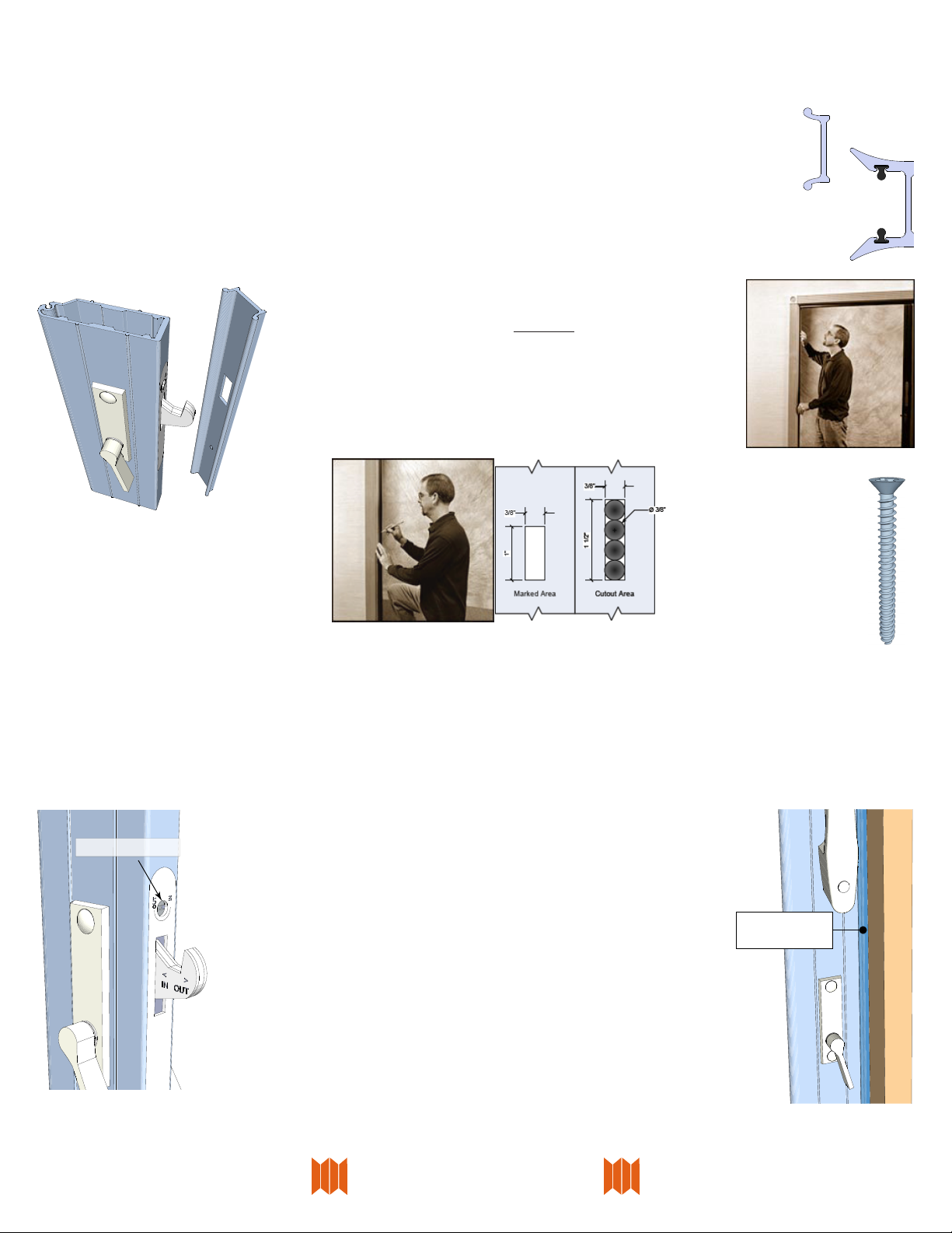
Stack the door to one end of the track (either side of the opening is OK) and
attach the other end of the track to the header. Use #8 x 1½” pan or truss head
screws through the rst 2 holes at the end of the track. Seat the head of the
screw rmly against the track.
If the screws didn’t go into a solid part of the header (soft stu like sheetrock
or acoustical tile doesn’t count) at least ¾”, now would be a good time to go to
the hardware store and get longer #8 Pan Head or Truss Head screws.
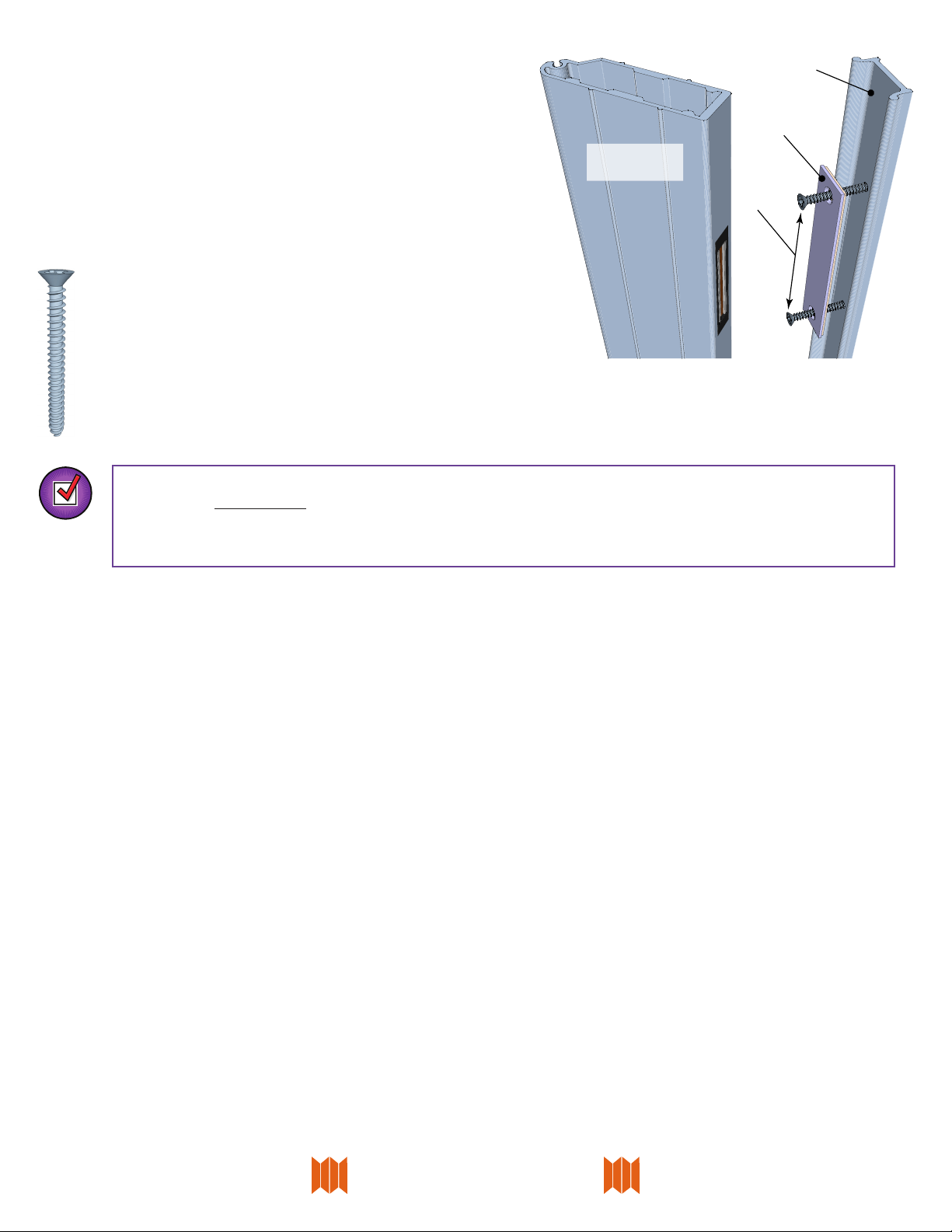
Transfer the door to the attached end of the track. Finish attaching the track
with #8 x 1½” pan or truss head screws.
Pin Track (track is in two or more pieces)
Some Pairs are shipped with two track section without alignment pins. If the track sections do not have alignment pin slots go
back to the Standard Track section and butt the track ends together in the middle.
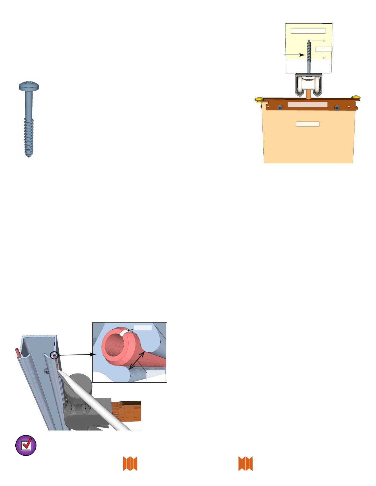
Find the longest piece of track. If they are all the same size, just pick one, any one. Insert the alignment pins into the groove of the
track at the end that will mate to the next section. The split in the pin MUST BE AWAY (perpendicular, see inset illustration below)
from the slot in the track. Drive the spring pins completely into one track using a hammer.
Thread the track onto wheels; lineup the wheels properly in the track grooves. Be careful not to insert the wheels sideways. You
won’t like the result.
Stack the door to one end of the track section and attach the other end of the track to the header. Use #8 x 1½” pan or truss head
screws to attach the track to the header. Start at the jamb side where the door will stack and put in enough screws to accommo-
date the stacked door. Seat the head of the screws rmly against the track.
If the screws didn’t go into a solid part of the header (soft stu like sheetrock or acoustical tile doesn’t count) at least ¾”, now
would be a good time to go to the hardware store and get longer #8 pan or truss head screws.
Transfer the door to the attached end of the track. Finish attaching the track with #8 x 1½”pan or truss head screws.
The doors may be heavy! Don’t be a hero! Let the track do the lifting for you!
Repeat the process of inserting the alignment pins and attaching to the header for each remaining track section.
Check it out! Move the door back and forth along the track looking for smooth operation. Most frequent problems include screw
heads sticking out, wheels sideways or debris in the track.
After the track has been secured, drive the alignment pins back halfway into the
second piece of track with a hammer and the edge of a screwdriver.
#8 x 1½ Pan or
Truss Head Screw
Pin Hinge Hardware
Body Panel
Structural Material
At least ¾”
Non-structural
Material
#8- 1½” Pan Head
Pin Split
Slot
Opening