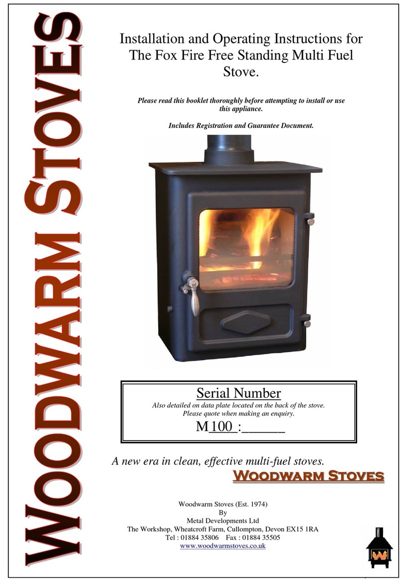
Woodwarm Stoves Phoenix 3 User guide

Conventional Flue Gas Stoves
Phoenix 3
Serial No: ………………………
INSTALLATION, SERVICING
AND USER INSTRUCTIONS
For use in GB & IE (United Kingdom and Ireland)
This appliance has been tested and certified for other counties (see technical data). However to install appliance in other
countries, modification of the appliance and its method of installation may be necessary in order to use the appliance safely and
correctly. The manual for the local language must be obtained. Contact Woodwarm for further information.
Document No. : User_Phoenix3_CF_10th Apr 2018
File: Office_Printers_GasStovesLit

GB & IE
2
This produst has been tested, and certified for use on Biopropane Gas.
Biopropane Gas can be used as a fuel, with no adjustment necessary if the product is installed as an LPG version.
This Manual covers the following Products:
Phoenix3

GB & IE
3
Content
1. General Notes 4
2. User instructions. 5
2.1 Emergency Gas Isolation 5
2.2 First Time of Operation 5
2.3 Control Overview 6
2.3.1 Remote Control 6
2.4 Manual Turn OFF 11
2.5 Cleaning and Maintenance 11
3. Installation instructions. 12
3.1 Gas Connection 12
3.2 Ventilation 12
3.3 Appliance Fireplace Installation 12
3.4 Flue Connection 13
3.5 Door Lock / Opening the Stove Door 14
3.6 Fuel Bed Arrangements 15
3.7 Commissioning the appliance 22
4. Servicing 23
4.1 Cleaning the Ceramics 23
4.2 Servicing the Burners 23
4.3 Spare parts 24
5. Technical Information 25
5.1 Countries of Use 25
5.2 Technical Data 26
5.3 Dimensions 27
5.4 Product Fiche 29

GB & IE
4
1. General Notes
This Woodwarm gas appliance is a High Efficiency, Live Fuel Effect appliance. It provides radiant and convected
heat using the latest burner technology.
Before Installation, check that the local distribution conditions, nature of the gas and pressure, and adjustment of
the appliance are compatible.
This appliance is intended for use on a gas installation with a governed meter.
This Gas Installation may only be installed by a registered professional competent person (Gas Safe installer in
the UK). The installation must adhere to the requirements of the local and national Building regulations and
national standards. The installation manual must also be followed.
Ensure that the Flue Terminal is not in any way obstructed and is clear of vegetation, i.e. trees, shrubs etc. and
that no objects are leant against the terminal or guard.
Always clean the Window Panel before the fire is ignited. Any finger prints must be removed, as these will be burnt
into the glass and will be un-removable.
Do not operate this appliance if the glass panel has been broken (or cracked), removed or is open.
The appliance is designed to fit numerous installation situations as listed in these installation instructions. However
only flue approved by Woodwarm for this appliance may be used.
This appliance is rated below 6.9kW, and as such needs no additional ventilation. However an adequate supply of
fresh air to maintain temperatures and a comfortable environment is recommended.
This appliance is designed as a heating appliance, and as such will get very hot in operation; all surfaces (except
the controls and access door) are considered to be working surfaces and as such should not be touched. The front
windows and surrounds are not considered to be fully secure guards against accidental contact. It is recommended
that an approved fire screen be used if children, the elderly or persons with limited mobility are to be present in
the same area.
Do not place curtains, laundry, furniture etc, within a safe distance of 300mm of this appliance.
Do not attempt to burn rubbish on this appliance.
If this appliance is extinguished, on purpose or other, no attempt to relight should be made within 3 minutes.
This appliance incorporates a ODS Monitoring system. This is located on the front of the Burner and must not be
adjusted by the installer. This ODS Monitoring system must not be put out of operation, and if any parts require
changing, only original manufacturer parts shall be used.

GB & IE
5
2. User instructions.
2.1 Emergency Gas Isolation
In the event of a gas leak or if gas is smelt, the appliance must be isolated. This is done by turning OFF the gas at
the Isolation Tap. This Isolation Tap Must Be fitted by the installation engineer as near as possible to the appliance
(within 2 meters of the appliance).
2.2 First Time of Operation
Before igniting the appliance, ensure that all packaging, safety stickers and any protective wrapping have been
removed, and that the glass has been cleaned, including all fingerprints from the glass.
Ensure that the room is adequately ventilated the first time that the appliance is ignited; we would recommend
opening windows if possible. Run the appliance at full setting for a few hours so that the paint gets an opportunity
to fully cure. During this period it is possible for some fumes and vapours to be given off. We would recommend
keeping children and pets out of the area at this time.

GB & IE
6
2.3 Control Overview
2.3.1 Remote Control

GB & IE
7

GB & IE
8

GB & IE
9

GB & IE
10
(IF FITTED)

GB & IE
11
2.4 Manual Turn OFF
In the event that the appliance needs to be turned OFF manually, for instance, if the remote control is lost or the
batteries become totaly flat, the control valve can be accessed and the switch flipped to OFF (marked “0”) (if
equipped).
The picture below shows the control valve.
The control valve is located behind the control hatch in the Base of the appliance.
2.4.1 To Turn OFF Gas To The Appliance
The appliance can be turned OFF by isolating the gas supply. This is done by turning OFF the gas at the Isolation
Tap.
2.5 Cleaning and Maintenance
This appliance should be inspected and serviced once a year by a qualified, competent and registered person. The
inspection and maintenance must at least ensure that the appliance is working correctly and safely. It is advisable
to clean the appliance of any dust and debris before regularly during the heating season and especially if the
appliance has not been used for some time. This can be done with a soft brush and a vacuum cleaner or a damp
cloth and if required a non-abrasive cleaning agent. Do not use corrosive or abrasive substances to clean the
appliance.
Manual OFF switch (if equipped)

GB & IE
12
3. Installation instructions.
Before commencing Installation, confirm that the details on the appliance data plate correspond to the local
distribution conditions, gas type and pressure to which the appliance is to be installed.
Ensure that gas supply and supply pipe is capable of delivering the required volume and pressure of gas and is in
accordance with the rules in force.
3.1 Gas Connection
This appliance has a gas inlet connection of Ø 8mm.
3.2 Ventilation
This appliance is rated below 6.9kW, and as such needs no additional ventilation. However an adequate supply of
fresh air to maintain temperatures and a comfortable environment is recommended.
This appliance may be installed in a completely sealed or mechanically ventilated house.
3.3 Appliance Fireplace Installation
Determine the position required for the appliance.
Create a gas connection for the appliance in approximately the correct location for the gas controls.
The gas controls are connected to the Burner of the appliance.
For clearance details see section 3.3.1. below.
The clearance distance of the Flue from combustibles must not be less than 75mm. This dimension can be reduced
to 25mm as the distance from the underside and the sides of Horizontal Flue runs.
The stove must stand on a fireproof hearth, which must be of a non-combustible material with a minimum thickness
of 12mm and extend 100mm in front of the stove.
The hearth must not be capable of inadvertent covering by a rug or carpet. This may be achieved by either the
hearth being 50mm above the level of the floor, or a fender or kerb around the hearth to a height of 50mm.
3.3.1 Clearance requirements
The appliance must not be fitted against a rear wall constructed from a combustible material; a gap of 300mm
should be given around the stove before combustible materials may be used in the wall construction.
If the appliance has to be located in an opening, the minimum clearance from non-combustible materials is:
To Rear : 50mm
To Right : 50mm
To Left : 50mm
The stove must be located at least 280mm from any combustible materials.
A combustible shelf may be fitted over the appliance, if in the case of a 150mm or less deep shelf, there is at least
280mm clearance above the top of the stove. The shelf depth may increase at the same rate as the increase in
clearance; i.e. a shelf depth of 200mm would require a clearance of 330mm.

GB & IE
13
3.4 Flue Connection
The chimney or flue system must comply with the rules in force, and must be a minimum of 125mm in diameter
(5"). The appliance is fitted with a 125mm flue connection, to use a 150mm diameter flue, a reducer will be
required.
The minimum effective flue height for the appliance must be 3 metres. Any horizontal flue run from the rear outlet
must not exceed 100mm from the back of the appliance.
The chimney or flue must be free from any obstruction. Any damper plates must be removed or secured in the fully
open position, and no restrictor plates fitted.
The chimney must be swept prior to the installation, but it need not be swept if it can be seen the chimney is clean
and unobstructed throughout its entire length.
NOTE: If it is intended to fit the appliance into an existing brick built chimney, a 5" (125mm) liner must be used.
Larger lined flues can work, but in some instances could cause cold start flue problems resulting in nuisance
shutdown. Lined flues above 7" (175mm) are not recommended.

GB & IE
14
3.5 Door Lock / Opening the Stove Door
NOTE! This appliance must never be used if the glass door panel is broken, removed or if the door is not
locked in to the closed position.
Before gaining access to the burner tray, first make sure that the stove is switched off and is cold.
Firstly remove the outer door, lift the door upwards then pull away from the stove.
Remove the 4no glass frame-locking nuts these can be removed using a 10mm spanner.
The glass frame assembly can now be removed to gain access.
Outer Door
Glass Frame Locking Nuts
Glass Frame Assembly

GB & IE
15
3.6 Fuel Bed Arrangements.
When arranging the Media into the Firebed, it is imporant that the Pilot area is kept clear and that no Media
enters the Pilot shield. The Pilot area includes the the pilot shield and the top of the burner to the first slot.
When comissioning or servicing the Appliance Cross Lighting must be checked to ensure smooth lighting of the
main burner from the Pilot Flame and smooth lighting of the effect burners from the main Burner.
3.6.1 Log Lay

GB & IE
16
Scatter the Bags of Embers over
the top of the burner as shown,
keeping the piot area and burner
outlets clear.
Position the 8 logs as shown.
If desired, lay the glow strands
amongst the logs in the flames to
create an enhanced Glow.
Log 1
Log 2
Position Log 1 Centrally on the
Burner, behind the central ports
on the Front Burner/.
Position Log 2 on top of the Right
Hand side of the Front Burner,
clearly to the Left of the Pilot.

GB & IE
17
Log 4
Log 5
Log 3
Position Log 3 on top of the Left
Hand side of the Front Burner.
Position Logs 4 so that it sits on
top of Logs 1,2 and 3.
Position Logs 5 so that it sits on
top of Log 4 in the centre, with
the bottom in the Left Hand Rear
corner of the Fire Box..

GB & IE
18
Log 6
Log 7
Log 8
Position Log 7 in the centre ,
sitting on the Grate, behind the
Log Bar, with the Top on Log 4.
Position Log 8 in the Left Hand
Rear Corner, resting on Log 5.
Position Log 6 so that the Top of
the Log sits on Log 4, with the
bottom extending to the Rear of
the Fire Box..

GB & IE
19
3.6.2 Coal Lay
Pack containing 30 Coals.

GB & IE
20
Position the 30 Coals as shown.
Coals 1 - 8
Coals 9 - 13
Coals 14 - 17
Table of contents
Other Woodwarm Stoves Stove manuals
Popular Stove manuals by other brands

FRANCO BELGE
FRANCO BELGE Hekla 634 10 49 manual

Breckwell
Breckwell SW500 Operation manual

wiking
wiking Volcanic 1 Mounting the plinth

Castelmonte
Castelmonte HELIOS PELLET Operating and maintenance handbook

Euro Appliances
Euro Appliances EO8060DX Usage and care guide

Dovre
Dovre ASTRO4GA - P Installation instructions & operating manual