manuals.online logo
Brands
  1. Home
  2. •
  3. Brands
  4. •
  5. Worcester
  6. •
  7. Boiler
  8. •
  9. Worcester Highflow 4.5 OF User guide

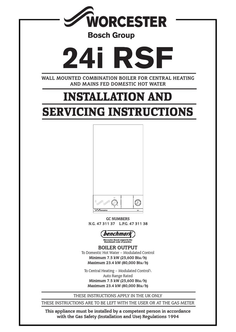
Worcester Highflow 4.5 OF User guide

.......-~
~
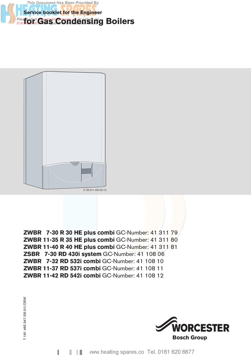
~ORCESTER---
Highflow
4.5
OF
FLOOR STANDING COMBINATION BOILER FOR
CENTRAL
HEATING
AND
MAINS
FED
DOMESTIC
HOT
WATER
INSTALLATION AND
SERVICING
INSTRUCTIONS
GC
NUMBER
41
311
41
BOILER
OUTPUT
To
Hot
Water On/Off Control
Maximum
22.9
kW (78,000
Btu/h)
To
Central Heating On/Off Control, Range Rated
Minimum
8.8
kW (30,000
Btu/h)
Maximum
22.9
kW (78,000 Btu/h)
IMPORTANT:
THIS
APPLIANCE
IS
FOR
USE
WITH
NATURAL
GAS
ONLY
THESE
INSTRUCTIONS
APPLY
IN
THE
UK
ONLY
THESE
INSTRUCTIONS
ARE
TO
BE
LEFT
WITH
THE
USER
OR
AT
THE
GAS
METER
~---------~~~ORCESTER
__________
~
Bosch Group
' CONTENTS
I.
GenerallnformatJon
II.
Electrical
2.
Technical
Data
12.
Removal
of
Cabinet
3.
Dimensions
and
Wall
Preparation
13.
lnstallatJOn
4.
Siting
the
Appliance
14.
Commissioning
the
Appliance
5.
Flue
15.
Users
Instructions
6.
Arr
Supply
16.
Routine
Cleamng
and
Inspection
7.
System
Considerations
17.
Replacement
of
Parts
8.
Sealed
Primary
System
18.
Short
Parts
List
9.
Open
Vent
Pnmary
Systems
19.
Fault
Fmdmg
10.
Domestic
Water
Supply
1.
GENERAL INFORMATION
See
Fig. 1
1. THE HIGHFLOW
4.5
INCORPORATES:
(a)
An
open flued low thermal capacity boiler having a
maximum
heat
output
of 22.9
kW
(78,000
Stu/hi
(b)
A
heatbank
having a nominal capacity of
92litres
(21
gallons)
of circulating primary
hot
water
and
positioned
at
the
side of
the
appliance. Acopper finned water to water heat exchanger
is
fitted into
the
heat
bank. Secondary mains supply domestic
hot
water
passes
through
the
heat
exchanger.
{c)
Adiverting valve to direct
the
boiler
output
either to domestic
hot
water
or central heating
as
required.
{d)
Two mtegral circulating
pumps.
(e)
A multifunctional gas valve
and
electrical control
system
to
individually control
the
domestic hot
water
and
central
heating.
(f)
Boiler
and
hot
water
temperature
control
thermostats
providmg control
for
central heating
and
domestic
hot
water.
(g)
An
Operating Switch for selection of
water
only or central
heating
and
water. A
programmer
kit
is
available
as
an
optional extra
(h)
An
expansion vessel,
pressure
gauge,
pressure
release valve
and
auto
air vent
to
enable
the
appliance to
be
connected
to
a
sealed
water
system.
{i)
An
electronic
pump
delay control
board
which enables
the
central heating
pump
to run on for a period of
about
5
minutes
after
each
operating cycle.
2. THE HEATING SYSTEM
The appliance
is
supplied for connection
to
a sealed
system.
IMPORTANT: The pipe
connections
made
throughout
the
system
must
be
capable
of sustaining a
pressure
of
up
to 3 bar.
when
the
appliance
is
fitted
to
an
existing installation
and
that
system
ts
upgraded
to
a sealed
system
then
the
water
connec-
tions
must
be
checked
and
replaced
if
necessary
If
thermostatic
radiator valves are
to
be
fitted to
the
system
then
they
must
conform
to
the
requirements
ofBS
276
7:1972.
Acombined cold feed
and
vent
pipe connection
is
availablefor
use
when
the
boiler
is
fitted to
an
open
vented
system.
See
Fig.
2.
Provision
is
made
in
the
top
panel
for access.
INSTALLATION REQUIREMENTS
The installation of this appliance
must
be
in accordance with
the
relevant
requirements
of
the
Gas Safety (Installation
and
Use)
Regulations,
local
Building
Regulations,
Building
Standards
(Scotland) {Consolidation), current
lEE
wiring regulations
and
bye
laws
of
the
local
water
undertaking.
It
should
be
in accordance
with
the
relevant
recommendations
of
the
following
British
Standards
and
Codes of
Practiceo
BS
6798:1987,
BS
5449:1:1990,
BS
5546:1:1990,
BS
5440:1:1990,
BS
5440:2:1989
and
BS
6891.
Gas Safety (Installation
and
use) Regulations 1984:
It
is
the
law
that
all
gas
appliances are installed
by
a
competent
person,
in
accordancewith
the
above
regulations. Failure
to
install appliances
correctly could lead
to
prosecution.
It
is
in
your
interest,
and
that
of
safety,
to
ensure
compliance with
the
law.
The
manufacturers
notes
must
not
be
taken, tn
any
way,
as
overriding
statutory
obligations.
3.
2
NATURAL GAS SUPPLY
The boiler requires 2.8 m3
/h
(98.5
ft
3
/hr)
ofgas.The gas
meter
and
supply pipes
must
be
capable of supplyrng this quantity
of gas
in
addition
to
the
demand
from
any
other
appliances
being served.
It
is
recommended
that
a 22
mm
dia.
supply
pipe
is
used
up
to
the
appliance. Under no
circumstances
should
the
size of
the
gas supply pipe
be
less
than
that
of
the
applianceinletconnection(22
mm
diameter). The
meter
outlet
governor
must
ensure
a nominal
pressure
of20
mbar
(8
in.wg.)
at
the
appliance. The complete installation, including
the
meter, should
be
inspected
and
tested
for
soundness
and
purged
in
accordance
with
the
recommendations
of
BS
6891.
Fig.
1. Appliance
water
flow diagram.
Flow-
--
----
regulators
Comb1ned
cold
feed
and
vent
p1pe
I
Open
vent
pnmary
systems
onlyl
Bmler
heat
exchanger
Bo11ersec110n
lrrnnnuuu,
Bumer
:3ealed
system
4. INSTALLATION WARNING:
CARE
SHOULD
BE
TAKEN
TO
ENSURE
THAT
NO
FOREIGN
MATTER
IS
LEFT
IN
EITHER
THE
GAS
OR
WATER
PIPEWORK
AS
THIS
COULD
CAUSE
DAMAGE
TO
THE
APPLIANCE
5. SAFETY VALVE
The safety valve
may
be removed
and
sealed
if
the
boiler
is
fitted to
an
open
vented
system.
The
safety
valve
drain
connection
must
be
directed
away
from
any
electrical
components_ See Section 13.8
6. ELECTRICAL SUPPLY
Mains
supply
240V-
50
Hz,
240
watts. External Fuse 3 amps.
7. CONTROLS
All
controls includedwith
the
applianceare specified
in
Section
18-Short
Parts List, included m
th1s
booklet. There
is
pro-
vision
for
a room
thermostat
and frost
thermostat
to be con-
nected to the appliance. See Section
11-Elt•c!rical
Thermostatic radiator valves can be used
in
the system
but
a
suitable by-pass
is
recommended with this type of controL
When using a sealed primary system, particular care should
be exercised
that
only radiator valves of high quality to
BS
2767,10
should be f1tted.
B.
DRAINAGE
Adrain cock to drain
water
from the boiler
and
the heat bank
is
fitted
in
the prpe connecting the primary
heat
bank
to the
sealed
system
pressure vessel. A drain cock should also be
fitted to the lowest point of the
system
9. MAINS COLD WATER SUPPLY PRESSURE
If
the mains supply pressure to the appliance
is
expected to be
low, it
is
recommended
that
a 22
mm
diameter supply pipe
is
used from the rising main to the appliance
10. SHOWERS, BIDETS, TAPS AND MIXING VALVES
Standard hot
and
cold
taps
and
mixing valves used with the
appliance
must
be suitable for operating
at
mains pressure.
The use ofa thermostatically controlled showervalve
will
give
added
comfort and safeguard against
flow
of
water
at
too high
a temperature.
If
a loose
head
shower
is
fitted then the hose
rnusl be fixed to prevent the shower
head
falling closer than
25 mm
(1
m_)
above the top edge
of
the
bath
to prevent it being
immersed
in
the
bath
water. Alternatively an anti-syphonage
device
must
be fitted. Hot and cold mains fed
water
can
be
supplied
to
an
over rim flushing bidet,
but
is
subject to local
Water Authority requirements.
3
11. APPLIANCE OPERATION
See
Fig.
1.
The appliance
output
is
range
rated
for central heating from
8.8
kw
(30,000
Btu/h)
to
22.9
kW
(78,000 Btu/h). The
output
is preset
at
15
kW
(51
,200 Btu/h).
If
this
output
is
not
suitable
it should be adjusted to
match
the central heating require-
ment. The domestic
hot
water
output
is
preset
at
22.9
kW
(78,000
Btu/h)
and
must
not
be adjusted. See Section
14-
Commissioning the Appliance.
The control
system
ensures
the
heatbank
is
maintained
at
the
temperature
set
by
the hot
water
temperature
control ther-
mostat
With the Operating Switch (or Programmer)
in
the heating and
hot
water
mode, priority
will
be given to satisfy
the
heatbank.
Hot
water
will
automaticallybe diverted
to
the
central heating
system, the
temperature
being regulated by the central
heating
temperature
control thermostat.
With
the
Operating Switch
(or
Programmer)
in
the domestic
hot
water
mode, no
heat
will
pass
into the central heating
system. Domestic
hot
water
may
be drawn
off
at
a nominal
rate of
21
litres/min. (4.5 gal/min.) governed by two pre-set
flow
restrictors located
in
the cold
water
inlet manifold.
The appliance includes a domestic hot
water
pump
and a
central heating pump. With the appliance
in
the domestic
hot
water
mode
both
pumps
are
energised. The domestic
hot
water
pump
circulates primary
water
around
the
heat
bank
and
the
centralheating
pump
circulatesprimary
water
around
the
heat
bank
and
the
boiler
With the appliance
in
the central heating
mode
the domestic
hot
water
pump
is
de-energised
and
the central heating
pump
is
energised. Primary
water
then circulates
around
the boiler
and
the
central heating system.
In
the
eventof an unacceptable rise
in
temperature
oftheheat·
bank
due to continuous operation of the burner a high limit
thermostat
is
fitted which
will
shut
down
the boiler. This over-
heating
is
caused
by a
tap
not being
turned
off properly and
allowing a very small flow of
water
past
the
heat
bank
control
thermostat
ph1al
An
overheat
thermostat
is
fitted
to
the
flow
pipefrom
the
boiler
section.
In
the event of a malfunction,
thE!
gas
pilot circuit
will
be interrupted which
will
completely shut off the gas valve
12. PACKAGING
The appliance
is
despatched
in
one
package
2.
TECHNICAL DATA
NOTE: THE DATA PLATE
IS
POSITIONED BEHIND THE
FRONT
PANEL
ON
TOP
OF
THE
ELECTRICAL
COVER
Table
1
NOMINAL
BOILER RATINGS
(1
0
minutes
after
lighting)
OUTPUT INPUT BURNER SETIING
GAS
RATE
PRESSURE
kW
Blu/h
kW
Btu/h
mbar
in_wg m3
/h
ft'
/h
8.8
30,000
12 1
41,300
2.5 1 0
1.15
40.7
11
37.500
14.9
50.800 4.0 1.6
1.42
500
13
44.350
17.5
59,700 s 8
23
1_67 58.8
15 51,200
19.9
67,900
7.0 2.8
1.90
66.9
17 58,000 22.5
76,800
9.0 3.6 2 1s 75 7
19
64,800
24 8 84,600 11.0
44
2 37 83 3
22 9
78,000
29.3
100,000
14.3
57
2.80
98.5
DOMESTIC HOT WATER
22.9 78,000 29 3 100,000 14.0 5.62 2.80 98.5
Note: The Pressure
test
point
1s
located
on
the
gas
valve
{See
Fig.
13
).
Table
2
SPECIFICATIONS
CENTRAL HEATING FLOW 28
mm
Copper tube
CENTRAL HEATING
RETURN
28
mm
Copper tube
COLD
WATER MAINS INLET 22
mm
Copper tube
DOMESTIC HOT WATER OUTLET 22
mm
Copper tube
GAS
INLET 22
mm
Copper tube
HEIGHT
860
mm
(33.9
in
1
WIDTH
685
mm
(27 in.)
DEPTH
600
mm
(23.6 in.)
WEIGHT
(DRY)
1
55
kg
(340
lbs.)
PRIMARY CAPACITY
981itres
(21.6 galls.)
MAXIMUM
STATIC
HEAD
25
metres
(81
ft)
MINIMUM
STATIC
HEAD 1 metre {39 in.)
CIRCULATING PUMPS
(2)
Grundfoss
UPS
15·60
EXPANSION
VESSEL
12\itres
charged 0.5
bar
MAXIMUM
OUTPUT
TO
HEATING
22.9
kW
(78,000
Btu/h)
OUTPUT
TO
DOMESTIC HOT WATER
22.9
kW
(78,000
Btu/h:
MAXIMUM
DOMESTIC HOT WATER FLOW
RATE
Nominally
21litres/min.
(4.5
gal/min.)
GAS
RATE
(after
10
min.) 2.8 m3
/h
(98.52
ft
3
/h)
MAXIMUM
CENTRAL HEATING FLOW TEMPERATURE
82°C
(180°F)
NOTE.
Appliance static
head
is
measured
from
the
top
surfaceof
the
appliance
or
the
highest
point
in
the
heating
system
to
the
top
of
the
water
level in
the
feed
and
expansion
tank. See
Fig_
7
Table 3
AVAILABLE
PUMP
HEAD
BOILER OUTPUT HEAD
MINIMUM
FLOW
RATE
TEMPERATURE
RISE
ACROSS
HEATING
kW
Btu/h
metres
feet
litres/min
gal/min
FLOW AND
RETURN
8.8
30,000
5 1 16.6
11.5
2.5
11
37.500
4.7 1s s 14.5 3.2
13
44,350
4.3 14.1
17.0
3.8
15
51,200
38
12.6
19.5
4.3 11
°(
(20°F)
17
58,000
33
10.9
22
s
49
19
64.800
2.2 7.2
24.8
54
22.9
78,000
1.7 5.5
30.0
6.6
4
3.
DIMENSIONS AND
WALL PREPARATION
Fig.
2.
Appliance dimensions
and
pipework connections.
l---600mm
i23.6tn)
-~~
685mm
i27tnl
320mm
11
f--
253
mm
(10
in.)
-j
225mm
I
2.6tnl
8.9tnl
Jinl1
185mm
17
Rear
view
rl
80mml3.1
'"'
6tnl
""ll
r
A
...
-+•
i
.--
-·
. BI-TcTo l
.G
____
E
BOILER
c "
'"
HEAT
BANK
0
~
M
E E
~
E
:c
f
f--
40mm(1
T
I <
~-
'"
"'
-
E E
E
~
" l
c
'"
~
~
E
E
0
~
E
E
WJ
172
mm
16
Btn
I
NOTE:
ALL
DIMENSIONS
ARE
NOMINAL
A
VENT
AND
FEED
122
mm
Copper)
B
CENTRAL
HEATING
FLOW
128
mm
Copper)
C
CENTRAL
HEATING
RETURN
(28
mm
Copper)
Fig.
3. Installation
and
servicing clearance
r600mmi236io(
l
I'
II
I
l1
II
II
D
DOMESTIC
HOT
WATER
OUT
(22
mm
Copper)
E
DOMESTIC
COLD
WATER
IN
i22mm
Copper)
F
GAS
INLET
l22
mm
Copper)
G
SAFETY
VALVE(~
mm
Copper)
I
I
I
I
I
I I
0
=
~
~
E
E
0
----l
I
I
I
I
I
I
I
I
I
I
--'~"---------'.-
--
_
_J
II
II
II
l1
II
LL
I I
::j
I I
I I
jj_
600mm
{24in)
I.
.I
SPACE
REQUIRED
FOR
INSTALLATION
AND
SERVICING
5
5mm
(0.2io)
---ft_
SPACE
REQUIRED
FOR
SERVICING
25mm
11m.)
SPACE
REQUIRED
AT
LEFT
HAND
SIDE
FOR
INSTALLATION.
70
mm
{2.8m.)
SPACE
REQUIRED
AT
RIGHT
HAND
SIDE
FOR
INSTALLATION
4.
SITING THE APPLIANCE
IMPORTANT
The appliance
must
not
be
installed
in
a
bedroom
orbed-sitting room
or
in
a room contaimng a
bath
or shower.
The appliance may
be
installed
in
any other room although particular
attention
is
drawn to
the
requirements of
the
current
I.E.
E.
Wiring
Regulations and,
in
Scotland,
the
electrical provisions of
the
Building
Regulations applicable m Scotland.
with
respect to
the
installation
of
Lhe
appliance
in
a room containing a
bath
or
shower.
1. The
appliance
is
floor
standing.
The floor
must
be
firm
and
level.
2. Siting
must
allowfor
the
proviston of
an
open
flue termination.
See Section
5-Flue
3. If
the
appliance
is
to
be
fitted
in
a
timber
frame building
then
it
must
be fitted
in
accordance
with
the
British Gas publication
"Guide
for Gas Installations in Timber Framed Housing".
5. FLUE
The appliance
must
be
connected
to a flue conforming to
BS71
5
and
incorporate a suitable
adapter.
The appliance flue
outlet
has
an
mternal
diameter
of
144mm.
The
flue pipe fitted
to
the
boiler
must
have
an
internal
diameter
of
1
25
mm
(5
in.).
If
the
outside
diameter
of
the
flue pipe
is
greater
than
1
44
mm
then
an
adapter
must
be
fitted.
An
acceptable
means
of disconnection e.g. a slip
or
split socket,
must
be
incorporated
in
the
installation immediately
above
the
draught
diverter.
The appliance
must
be
connected
to a flue wh1ch
will
provide a
consistent up-draught
without
undue
cooling of the flue gases. The
requirements
of
BS
5440:1
should
be
followed.
Horizontal flue runs
should
be avoided
and
the
flue should
terminate
in
accordance
with
the
relevant
recommendations
given
in
BS
5440:1 The flue
must
be
fitted with a
term
mal which
has
been
tested
and
found satisfactory
by
British Gas. The terminal
must
not
be
installed w1thm
600mm
(24
in.)
of
an
openable
wmdow, air
vent
Or
any
other
ventilation opening.
F.x1sting
ch1mneys
may
be suitable
but
must
be
swept
first
and
usually require
an
approved
liner to be fitted.
If
in
doubt
regarding
the
suitabillty of a flue,
consult
the
local Gas Region for advice.
!f
the flue
is
required
to
be
taken
through
the
wall behind
the
boiler
then
adequate
space
should
be
allowed for a suitable flue
bend
to
be fitted Right
angle
bends
must
not
be
used.
When
the
flue
is
taken
through
a ceiling
and
into
the
roof
space
or
room above.
it
must
be
provided with a sleeve of non-combustible
material suff1cient to allow an
a1r
space
between
the
sleeve
and
the
flue of 25
mm
(1
in.)
mm1mum. Asuitable non-combustible sleeve
or plate
must
be
fitted
to
centre
the
flue
and
maintain
the
25
mm
6
4. The following
clearances
must
be
left
to
allow for seJVicing
and
ventilation:
(a)
Above
the
appliance,
(b)
In front
of
the
appliance,
(c)
Left·hand
sideo
(Viewed from front)
(d)
Right·hand
sideo
(Viewed from front)
Servicing
450
mm
(18 in.)
Ventilation 5
mm
{0.2
in.)
Servicing
600
mm
(24 in.)
Ventilation
150
mm
(6
in.)
SetVicing
25
mm
{1.0
in.)
Ventilation 5
mm
{0.2 in.)
Servicing 70
mm
(2.8 in.)
Ventilation
70
mm
{2.8 in.)
If
a
standard
work
surface is
fitted
then
the
gap
should
be
1
00
mrn
(4
in.)
Take
care
to
ensure
that
adequate
space
is
available
at
either
side
to
manoeuvre
the
appliance
during installation.
This is left
to
the
discretion of
the
installer.
5.
Refer
to
Sections 2, 3, 5, 6
and
7 for additional information.
(1
in.)
air gap. The
space
between
the
plate
or
sleeve
and
the
flue
pipe
should
be
filled with mineralwool
or
similarnon·combustible,
non
conducting
materials
IMPORT
ANT:
It is
ESSENTIAL
to
ensure,
in
practice,
that
products
of
combustion
discharging
from
the
terminal
cannot
re-enter
the
building
or
any
other
adjacent
building
through
ventilators,
windows,
doors
or
other
sources
of
natural
air infiltration
or
forced
ventilation
or air
conditioning.
If
this
eventuality
should
occur,
the
appliance
MUST
be
turned
off
immediately
and
the
local Gas Region called in
to
investigate.
6. AIR SUPPLY
The appliance
must
have
clearance
at
the
right
hand
side for air
movement
of
at
least
70
mm
(2.8
in.)
or
100
mm
(4
in.)
if
a work
surface
has
been
fitted above
the
appliance. See Section 4.
The appliance
must
not
be
boxed
in
tightlywith kitchen
cupboards
etc.
Air
supply
must
be
provided
in
accordance
with
BS
5440:2.
1.
If
the
appliance
is
installed
in
a room,
then
the
room
must
have
a
permanent
air
vent
direct to
outside
air,
or
to
an
adjacent
roomwhich itself
has
a
permanent
air
vent
directto
outside
air.
The minimum effective
area
of
the
air vent(s) required
is
1
DO
cm
2 (15 in2).
2.
If
the
appliance
is
installed in a
cupboard
or
compartment,
permanent
air
vents
are
required
in
the
cupboard
or
compart·
ment,
one
at
high level,
and
one
at
low level, either direct to
outside
air
or
to a room. Both high
and
low level air
vents
must
commumcate
with
the
same
room
or
must
both
be
on
the
same
wall
to
the
outside
air. The minimum effective
areas
are
given
in
Table
4.
Where
the
cupboard
or
compartment
is
ventilated to a room, the room itself must have an air vent
dtrect
to
the outside air
of
a minimum effective area
of
1
DO
em'
(15
in.'). Details of essential features
of
cupboard/compartment
design, including airing cupbaord installation, are given
in
BS
6798:1987
3. If there
is
any type
of
extract fan fttted m the premises. spiltage
of
the products from the appliance
flue
could occur when the
fan
is
operating unless an adequate air inlet area
from
outside
is
provided.
4.
A spillage test as detailed
in
BS
5440:1 must be carried out and
any remedial action taken to ensure the installation meets
these standards
Table 4
Position
Air
from
Air
direct
Air
Vents room from outside
H1gh
Level
264 em' 132 em'
(41
in')
(20.5 in
'I
Low
Level
528
cm
1 264
cm
1
(82 m.')
(41
in.')
Additional information
in
respect
of
air supply and installation data
is
given
in
BS
6798 and
BS
5440:Part
2.
7.
SYSTEM CONSIDERATIONS
1.
For
circuit design purposes
it
is
most important
that
the
flow
rate and pressure drop across the appliance corresponding to
the system
temperature
differential
and
maximum heating
output chosen, should be as given
in
Table
3
2.
The
appliance includes a central heating circulating pump and
no
other circulatmg pump IS required. When fitting a room or
frost thermostat refer to Section 11--Eiectrical.
The
appliance
will
operate sat1sfactonly on a two pipe small bore
or
microbore
system
3. The
heatbank
contains two finned copper
heat
exchangers
which provide domestic hot water A control system
is
incor-
porated that gives priority to the domestic hot water and the
central heating
will
be turned
off
when a demand
for
hot water
IS made.
For
large quantities
of
hot water the
Hot
Water
Tem-
perature Control
Knob
should be set at maximum and after use
a
few
minutes may be reqmred to re-heat the heatbank.
The
central heating
will
remain
off
during this period
4. The appliance
IS
supplied suitable
for
direct connection to a
sealed system
5.
It
is
essential that the fittings and joints
in
a sealed system are
capable
of
maintaining the chosen system pressure.
It
is generally advisable to
fit
a by-pass to all systems.
8.
SEALED PRIMARY SYSTEM
See
Figs.
5 and 6
1. GENERAL
The installation
must
comply with the requirements of
BS
6798:1987 and
BS
5449:1
For
sizes
of
flow
and return pipe
work refer to Section
2-
Technical Data and
Fig.
2
The open end
of
the combined feed and vent pipe
must
be
sealed
IMPORTANT:
The pipe connect10ns
made
throughout
the
system must be capable
of
sustaining a pressure
of
up to 3 bar
When the appliance
is
fitted
to
an existing installation and that
system
is
upgraded to a sealed system then the water con-
nections must
be
checked and replaced
if
necessary
2.
SAFETY
VALVE
The spring
loaded
safety
valve
is
set
to
operate
at
3
bar
(45
p.s.i.). The discharge pipe
must
be
so
arranged
that
the
discharge of
water
or
steam
from
the
tundish pipe
cannot
create
a
hazard
to
occupants
of
the
premises
or
cause
7
damage
to
electrical
components
and
wiring. See Section 13
-Installation.
The safety valve complies with
the
general requirements of
BS759.
3.
PRESSURE
GAUGE
A pressure gauge fitted to the appliance covers the range
0-4
bar
(0-60
p.s.i.)
4.
THE
EXPANSION
VESSEL
The
appliance incorporates a 12 litre diaphragm type expan-
sion vessel charged to 0.5
bar.
The
expansion vessel
is
charged
with air and
is
fitted wtth a Schraider type valve.
The
charge
pressure
!S
therefore
adjustable
by using a tyre
pump
and
pressure gauge and should be increased
if
necessary.
The
charge pressure must not be less than the static head
at
the
point
of
connectiOn
(i.e.
height
of
the top point
of
the system
above the expansion vessel)
The
vessel as supplied
is,
therefore,
SUitable
for
systems with a
static heat
of
0.5 bar whtch
1S
equivalent to 5 metres (17ft.)
5.
SYSTEM
VOLUME
The
expansion vessel accommodates differing system volumes
depending upon the initial charge pressure and pre-pressurisa-
tion of the system
if
any.
Reference should be made to
Table
5
to
establish
the
approximate
system
volume
that
can
be
accommodated under different conditions with the standard
expansion vessel.
If
it
is
found
that
the system volume
is
in
excess of
that
catered
for
by the expansion vessel supplied,
then an extra vessel can be added as close to the return con-
nection
of
the appliance as possible so that the total expansion
volume
is
sufficient
Refer
to
BS
5449:1 and
BS
6798:1987
for
further information.
Table 5
TOTAL
SYSTEM VOLUME IN LITRES (Gallons)
Initial System Initial Charge Pressure (bar)
Pressure (bar) 0.5 1 0
15
0.5
156
- -
(35)
1.0
96
122.5 -
(21) (27)
15
51.5 69.5 85
(11.5)
(155)
(185)
2.0 24 32.5
395
(5.5) (7)
(9)
NOTE.
Because
of
the increased primary· capacity
of
this appliance
care should be exercised over the correct sizing
of
the expansion
vessel
In
order to check that the standard vessel
(or
standard vessel
together with any supplementary vessel) capacity
is
adequate,
first
ensure
that
with
the
system
cold the initial
system
pressure
is
correctly set.
Allow
the system to heat
fully
with the hot water and
central heating thermostats set to maxtmum.
Check
that the system
pressure
has
not
exceeded 2.6
bar
If
the
system
pressure
has
exceeded
2.6
bar
a
supplementary
vessel
should
be fitted as
described previously or
if
one has already been fitted then this
should be increased
1n
size.
6.
MAKE·UP
Provision
must
be
made
for replacing
water
lost from the
system either from a make-up vessel mounted
in
a position
h1gher
than the top point
of
the system and connected through
a non-return valve to the
system
on the return side on the
heating circuit.
See
Fig.
5.
Or,
where access
to
a make-up vessel
would be difficult, provision
for
make up can be made by
pre-
pressurisation
of
the system.
The
appliance
must
not
be
operated
without
the
system
being full of
water
and
properly vented. Repeated venting
will
reduce
the
quantity
of
water
in
the
system.
It
is essential
that
this
water
is replaced
and
the
system
pressure
main-
tained.
7.
MAINS
CONNECTION
Connection to
the
mains
water
supply
or
to a
water
storage
cistern supplying
domestic
water
even
through
a
non
return
valve
must
not
be
made
without
the
approval
of
the
local
Water
Authonty.
8. FILLING
The system should be fitted with a
filling
point at
low
leveL
Methods
offilling
and
making
up
sealed
systems
aredescribed
in
BS
5449:Part
1 Two
methods
of filling a sealed
system
are
shown
in
Fig.
6
9. VENTING
The
automatic
air
vent
fitted to
the
appliance
is
fitted with a
protective black plastic screw
cap_
This
should
be
removed
and
discarded.
Air
will
now
automatically
be
vented
from this
point during
fil!ing.
See
Fig.
29.
The heating
system
should
be
fitted with
manual
air
vents
at
all
h1gh
pomts.
1
0.
COMMISSIONING
For
a
complete
description of
the
commissioning
procedure
refer to Section
14-Commissioning
the
Appliance.
(a)
Flush
the
whole
system
with cold
water
and
fill until
the
pressure
gauge
registers 1
.5
bar
(21
.5
p.s.i.). Clear
any
air locks
and
check
for
water
soundness
(b)
Check
the
operation
of
the
safetyvalve. Release
water
from
the
system
until
the
initial
system
design
pressure
is
obtained,
taking into
account
any
difference in height
between
the
pressure
gauge
and
the
point
at
which
the
pressure
vessel
is
connected.
NOTE:
The initial
system
design
pressure
should
be
0.3
bar(4.5
p.s.i.) plus
the
static
head
of
the
system.
Total
pressure
must
not
exceed
1.
5
bar
{21.5 p.s.
i.).
(c)
Light
the
boiler
and
heat
the
system
to
maximum
working
temperature.
Check for
water
soundness.
Turn off
the
appli-
ance
and
drain
the
system
while it
is
still hot.
(d)
Refill
and
vent
the
system.
Adjust
to
the
initial
system
design
pressure. Any
set
pointer
on
the
pressure
gauge
should
be
set
to coincide with
the
indicating pointer.
Fig.
5. Sealed primary water system.
~-------.,
r--------
..
rj
llllllll, JIllI
Ill"
L-------..1
1 I
1--------..1
I
* * * *
---
i--
----
_____
....!._
--r--~-
------
.J
____
..,
I I I
--~-------------...1-------------..,
I
I I
'I I
I
NOH:
A
DRAIN
COCK
SHOULD
BE
I
INSTALLED
AT
THE
LOWEST
I
POINT
OF
THE
SYSTEM
AND
I
BENEATH
THE
BOILER
I
I
I
I
~~J:~Hl:l!
II
~
Jl\11~!;0~~
f----
11.
SYSTEM BY-PASS
A suitable by-pass
designed
to give
the
minimum
flow
rate
corresponding
to
the
heating
output
US!~d
must
be
fitted. See
Table 3.
A suitable position for
the
by·pass
is
shown
in
Fig.
5. The by·
pass
should
be
connected
in 22
mm
dfameter
pipe
at
least
2
metres
(7
ft.) from
the
appliance
and
fitted with a suitable
valve
to
provide
adjustment.
To
adjust
the
by-pass,
the
boiler
should
be
operated
on
central
heating
with
the
system
by-pass
and
radiator
valves
set
fully
open
for
at
least
45
minutes. With
the
aid
of
a
contact
thermometer,
balance
the
heating
system
and
restrict
the
by-
pass
by
the
minimum
amount
necessary
to
givea
temperature
rise
across
the
flow
and
return
pipe of
11
°C (20°F).
12.
PUMP
The central
heating
pump
has
been
set
at
MAXIMUM
and
must
not
be
adjusted.
SPHERICAL
PLUG
BALL
VALVEFORA~CE
SERVICING
""
DOMESTIC
COLD
WATER
TO
TAPS,
SHOWER
ANOW.C
I
r-"---
BRITISH
STANDARD
STOP
VALVE
FIXED
SPINDL£TYPE
:
MAIN
~--2m(7ft1
MIN.--
r--,
I
I -
DOMESTIC
HEATING
RETURN
:
HOT
I I
WATER
HEATING
FLOW
_1_
__
~---,
I ! : e
I
I
lfl
F
AUT0~1TIC
1
1
I I
j
SUPPLEMENTARY
EXPANSION
VESSE
I I I
AIR
VENT
I
Refer
tro
Section
8
'
Paragraph
5.
I
FLOW
RESTAICTORS
BOILER
I
• I
0
HEAT
0
~
BANK
~
~
~
~
~~
~
EXPAJSION
~a?
~
PRfSSURf
1
~*
'!'
GAUGE
VESSEL
APf'LIANCE
I
CASING
I
------------------~
8
Fig.
6.
System filling
and
make-up.
Heating
Return
Non
return
valve
+-
Non
return
valve
~
Hose
un1on
l
t--...y<llt--r--{..-0..--..
----,
,.
~
See
Fig.
7
!J
f!
Stop
cock
::eo==~/'
Test
cock
Temporary
hose
9.
OPEN VENT PRIMARY
SYSTEM
1. For sizes of flow
and
return
pipework
refer
to
Section
2-
Technical
Data
and
Fig_
2
2. FEED
AND
EXPANSION
CISTERN
The feed
and
expansion
pipe
must
rise
continuously
from
the
appliance avoiding
any
horizontal runs.
The cistern
must
be
arranged
to
provide
a
minimum
static
head
of 1
metre
(39
in.}
above
the
top
of
the
appliance
or
above
the
highest
point
in
the
heating
circuit
whichever
is
the
greater.
3. SAFETY VALVE
A safety valve
is
not
required
on
an
open
vented
system.
If
preferred.
it
may
be
removed
from
the
appliance
and
the
tapping
blanked
off.
If
the
valve
is
left in position, a discharge
pipe
must
be
fitted which
terminates
in a position
such
that
if
water
or
steam
is
discharged
itwould
not
cause
a
hazard
to
the
occupants
of
the
premises
or
damage
the
electrical com-
ponents
and
wiring. See
Fig.
5
Fig.
7_Open vent water system.
EXPANSION
TANK
4.
Heating
Return
Auto
air vent
.....
.....,
....
_
Fill
Point
'
Heating
Return
FILLING
AND
VENTING
300mm
112m)
min.
above
the
highest
pomt
of
the
system
An
auto
air
vent
{which initially requires
the
top
to
be
loosened)
is
fitted
to
the
top
of
the
insulated
heat
exchanger
adjacent
to
the
boiler. See
Fig.
29.
Air
should
be
released
as
necessary
from
this
point
during
filling. Any
other
air within
the
appliance
will
be
expelled via
the
feed
and
vent
connection
or
dissipated
into
the
restof
the
system.
The
heating
system
should
be
fitted with
manual
air
vents
at
any
high
point
5. SYSTEM BY-PASS
A suitable by-pass
must
be
fitted,
designed
to
give
the
minimum
flow
rate
indicated
in
Table 3
corresponding
to
the
heating
output
used. A suitable position for
the
by-pass
is
shown
in
Fig.
5_
The
by-pass
should
be
connected
in
22
mm
diameter
pipe
at
least
2
metres
(7ft.) from
the
appliance
and
fitted with a suitable valve
to
provide
adjustment.
To
adjust
the
by·pass,
the
boiler
should
be
operated
on
central
heating
with
the
by-pass
and
radiator
valves
set
fully
open
for
at
least
45
minutes.
With
the
aid
of
a
contact
thermometer,
balance
the
heating
system
and
restrict
the
by-pass
by
the
minimum
amount
necessar~
to
give a
temperature
rise
across
the
flow
and
return
pipes
of
11
°(
(20°F)
6.
PUMP
The
central
heating
pump
has
been
set
at
MAXIMUM
and
must
not
be
adjusted
DOMESTIC
COLD
WATER
TOT
APS.
SHOWER
h
ANDWC
-------
1"-~~~-="t----
---
-j-
--
T-
--
-,
I
STATIC
HEAD
L_
-
r--------.,
,.--------.,
,J
llllllll,
.J
1111111
L
1..-------..1
I '
._
_______
...
'
~
* * *
---
i---
---
_____
...~__
-T----
______
_.L
___
- •
I I I
--~---------------L-------------,
I
I
I
NOTE:
A
DRAIN
COCK
S'lOULD
BE
I
INSTALLED
AT
THE
LOWEST
I
POINT
Of
THE
SYSTEM
AND
I
BENEATH
THE
BOILER.
I
I
I
I
I
I
Jlllllll
II
II;:;~~
I
I
I
l I
I
LOCKSHIELD
I
VALVE
'
SPHERICAL
PLUG
BAll
VALVE
FORA~ANCE
COMBINED
SERVICING
\:-,.
FEED
AND
VENT
~
~--2m171t1MIN.--
-,
I
HEATING
RETURN
:
I
HEATING
HOW
I
I
I l
I
r-
BRITISH
STANDARD
STOP
VALVE
FIXED
SPINDLE
TYPE
I
MAIN
DOMESTIC
HOT
WATER
-----
I
I
I
I
~-t
I
lfl
ll
AUTOMATIC
MINIMUM
ST
A
Tl
CHEADTOBE
1m
FROM
THE
TOP
I I I
AIR
VENT
I
HOW
RESTRICTORS
BOILER
•
HEAT
:;;
BANK
~
-~
~
PRESSUR£
J.
EXPA;SION
~~
~
GAUGE
VESSEL
APPLIANCE
CASING
9
13ft)
MEASURED
SURFACE
OF
TH
E
APPLIANCE
OR
OINT
IN
THE
THE
HIGHEST
P
HEATING
SYSTE
M
TO
THE
TOP
OF
EL
IN
THE
FEED
NTANK
THE
WATER
LEV
AND
EXPANSIO
10.
DOMESTIC WATER SUPPLY
See
Figs. 5
and
7.
NOTE:
The
following mstructions are general installation recom-
mendations
and
reference
should
be
made
to
the
local
Water
Authority before fitting
any
of
these
appliances.
In
the
event
of
difficulty please contact the manufacturer
1.
MAINS
COLD
WATER
INLET
Connection
is
made
as
shown in
Figs
5 and
7.
Devices
capable
of
preventing
the
flow of
expansion
water
should
not
be
fitted
unless
separate
arrangements
for
expansion water are
made_
The
final600
mm
(23.6 in.)
of
the
mains
cold
water
connection
to
the
appliance
should
be
made
in
copper
only
2. HOT
WATER
SUPPLY
AND FLOW REGULATION
The
appliance
1s
fitted
w1th
two
water
flow regulators
The
maximum
flow of
domestic
hot
water
available
through
the
appliance
is
limited
to
21
litres/min.
(4.5
gal./
min.).
NOTE:
The flow regulators
contained
within
the
flow
regulator
housing
are
plastic.
Do
not
heat
the
housing
during soldering
operations
on
adjacent
joints, e.g.
remove
and
replace after
soldering
11
. ELECTRICAL
See Figs. 8, 9. 10
and
11
NOTE.
Sw1tch off the
mains
supply
before removing
the
control
box
cover
ro gain
access
to
the
electrical terminal
stnp:
(a)
Remove
the
cabinet
top
panel
by
snatching
squarely
upwards
(b)
Release
the
five pozi·drive
screws
securing
the
cover
of
the
electncal control
box
and
remove.
ROOM
AND FROST
THERMOSTATS
If
the
room or frost
thermostat
1s
to
be
fitted,
it
should
be w1red into
the appliance terminal strip
as
shown
in
Fig.
8. One
or
both
of
the
blankmg plugs
must
be
removed
from
the
electncal
cover
and
the
cable
passed
through
the hole. A Heyco cord strain rel!ef
bush
(packed c,eparately with
these
mstructions)
must
be
used
to retain
the cables at
th1c,
point. The cables
should
be
routed
neatly
away
from
hot
sur!aces
to
a
convenient
ex1t
pmnt
from the cabinet.
MAINS
WIRING
The
method
of connectiOn to
the
appliance
must
facilitate
the
complete
!solation of
the
appl!ance, preferably via a 3
amp
fused
thrce·pin plug
and
unswitched
shuttered
socket outlet,
both
complymg
with
the
requirements
of
BS
1363. Alternatively con·
nection
may
be
made
via a
double
pole isolator with a
contact
separation
of 3
mm
in
all
poles
and
supplying
the
boiler
and
controls
only
Mains Cable: 0.75
mm
2 (24 x
0.20
mm)
to
BS
6500
Table 16.
Temperature
rated
at
100°C.
Should
the
factory fitted
mains
cable
need
to
be
replaced
then
the
new cable
must
be
connected
into
the
terminals
marked
l,
Nand
+at
the
left
hand
side of
the
appliance
terminal strip. The
cable
should
then
be
passed
through
the
cable
clamp
located
in
the
left
hand
side of
the
electrical
cover
and
clipped
to
the
two
cable
retaining clipsfixed
to
the
left
hand
sidepanel.Care
should
be
taken
that
the
cable
is
clipped
neatly
into place.
NOTE.
Ensure
that
the
earth
wire
is
longer
than
the
live
and
neutral
conductors
so
that
they
become
taut
before
the
earth
10
3.
TAPSANDVALVES
Hot
and
cold
taps
and
mixing valves
used
with this
appliance
must
be
suitable
for
operating
at
mains
pressure
4.
SHOWERS
(FIXED HEAD TYPE)
No
anti·syphonage
arrangements
are
necessary
5.
SHOWERS
(LOOSE
OR
FLEXIBLE
HEAD
TYPE)
If
a loose
head
shower
with
flexible
hose
is
to
be
used
over a
bath,
the
hose
must
be
fixed
so
that
the
head
cannot
fall
closer
than
25
mm
(1
in.)
above
the
top
edge
of
the
bath
in order
that
the
head
is
prevented
from being
immersed
in
bath
water~
Alternatively
the
shower
must
incoprorate
or
be
fitted
with
an
anti·syphonage
device
at
the
point
of
the
flexible
hose
con·
nections.
6. BIDETS
The
supply
of
hot
and
cold
mains
water
direct
to
a
bidet
is
permitted
provided
that
the
bidet
is
of
the
over·rim flushing
type. The outlet(s)
should
be
shrouded
and
unable
to
have
any
temporary
hand
held
spray
attached
No
anti·syphonage
arrangements
are
necessary
7.
USE
IN
HARD
WATER
AREAS
If
the
appliance
is
used
in
any
area
where
the
temporary
hardness
exceeds
200
ppm
a
Worcester
'In·Line' scale
inhibitor(available from
Worcester
Heat
Systems
Ltd.)
must
be
fitted into
the
cold
supply
to
the
appliance
Installation
should
be strictly
in
accordance
with
the
require·
ments
of
the
local
Water
Authority.
An
isolating valve
to
facilitate serv1cing
may
be
incorporated.
The
external
wiring
between
the
appliance
and
the
electrical
supply
shall
comply
with
current
lEE
Wiring Regulations,
and
any
local
regulations which apply. The
appliance
must
be
earthed.
SAFETY CHECK
In
the
event
of
an
electrical fault
after
installation of
the
appliance,
preliminary electrical
system
checks
shall
be
carried
out
(i.e.
earth
continuity, polarity
and
resistance
to
earth,
etc.),
as
described
in
the
British Gas Multimeter Handbook.
Fig.
9. Room
thermostat
and
frost
thermostat
connections.
ROOM
THERMOSTAT
CONNECTIONS
REMOVE
UNK
-c
ri,J
t
HONEYWELL
ROOM
THERMOSTAT
6160
OR
SIMILAR.
FROST
THERMOSTAT
CONNECTIONS
A
SUIT
ABLE
2-POLE
FROST
THERMOSTAT
I
I I
240V-..
50Hz
BOILER
MAINS
SUPPLY
Fig.
10. Functional flow
diagram-Hot
water
mode.
SUPPLY
l
240V~
50
Hz
FUSE
be
3A
DHW
HIGH
LIMIT
THERMOSTAT
--
-----
OPERATING
SWITCH
'
'
'
114 :
hi
TL
1
be
m
ROOM
THERMOSTAT
hi
~
PUMP
DELAY
TIMER
BOARD
hi
I
eLu
'
'"
CENTRAL
HEATING
PUMP
IL,
-·
T10
e
be
bl
hi
7J
be
m '
r---
-----------------------
'
I
e
L_-
'
w
\\
~!
'
T2
gTJ
m ' g .
J'
T12
: W
w :
~
e
pk
.
-~
•
l
DOMESTIC
HOT
WATER
CONTROL
THERMOSTAT
----------
PROGRAMMER
IIF
FITTED)
'
T9
I
~
f-.
::.(9=~
DOMESTIC
HOT
WATER
pk
HIGH
LIMIT
THERMOSTAT
T4
lbk
T5
bt
......
T7
g
be
bl
v~
I
f,A\
IOLfNOIO
CENTRAL
H[ATI~G
bl
I
~J\!V
bl
CONTROL
RELAY
I I
1\IJPO~[S\OF~
r ,.
hv
T8
I9
~
bt
I
V\
bl
,.
w I
~'''["TING
'0•\L'o'[
p w
~
4l
10
I
J-
w
11
7
..
lE~
T~AL
H[ATING
~m
••
-(JNTR~II
THfR~Q\TAT
T6
be
bl
N
N
N
N
N
N
N
.~
y
ru:
~
hk
~12
8
Vv_.l
Tl~r
N
.
..::..
w
m:
'
be
e
------
-
--
_j
COL
OUR
CODE
hi
BLUE
bk
BLACK
br
BROWN
y
YELLOW
pk
DOMESTIC
HOT
WATER
PUMP
bt
pk
PINK
or
ORANGE
VIOLET
w
WHITE
T13
""
I
pk
r
RED
g y
GREEN
YELLOW
GREY
PURPlE
GAS
SOIE~OID
DOMES!
C
HU.
w•HR
hi
bl
~
N
N
Fig.
11. Functional flow
diagram-Central
heating mode.
SUPPLY
240V-
L
50
Hz
-
FUSE
bt
TL
3A
DHW
HIGH
LIMIT
~~
THERMOSTAT
i
oPe-RATING
sw,TcH
--: I • I
bt
~-.t
T~
:
bl
ROOM
THERMOSTAT
~:
br
r-----
w '
T2
+*
lJ
T3
g
T\1
' g - •
Ill
T12
; W
~
Jj
'1:
rl"k
'
I
"'
-
-----
___
_j
•
l
DOMESTIC
HOT
WATER
CONTROL
THERMOSTAT
------
--
PROGRAMMER
IIF
FITTED
I '
I I-f-
DOMESTIC
HOT
WATER
hi
PUMP
DELAY
TIMER
BOARD
hi
.,
.
-~
~
•
Ls
-·
CENTRAL
HEATING
PUMP
T '
T10
be
bl
m
bl
__________________________
.,....
g
T7
lu
bl
--~
~,A>
\Cl!NOIC
C!NlRAl
H!
4TI~G
bl
~v"
l
bl
CONTROL
RELAY
louPPR!'i\00~
1
..
I.!.
se I
T8
bt
bl
9
e-vv--e
,
..
UJ
DIVfRliNG;~·.y[
p w
6•
T9
10
.~J
w
3
..
i
~
~~
ck
HIGH
LIMIT
THERMOSTAT
11
J.
nm
CE~TR4lH!ATING
•
.:-.
g
Tll:
.
..::...
w
T12
:
'
bt
i
-------
______
_)
'--
co
LOUR
CODE
bl
BlUE
bk
BLACK
br
BROWN
v
YELLOW
T4
lbk~
/
bk
pk
DOMESTIC
HOT
WATER
PUMP
bt
pk
PINK
or
ORANGE.
VIOLET
w
WHITE
be
~
12
8
lT!L,
n~f
pk
r
REO
g y
GREEN·YELLOW
11
CIINTR-JllH!RMOSW
T6
"'
Vv
I
-.
I I
GAl
S01
f~OI~
00'.'(\TI(
><01
WAHR
GREY
PURPLE
bl
bl
bl
~
~
----
N
N
N
N
N
N
N
N
N
N
W
y
c=J(
be
,----,
rr---]'
~
\'l__.
'~,_
-I
I
CE'IJTRAL
HEATI'IIG
lco.r
PUMP
~'
bl
br
9Y
DOMESTIC
HOT
WATER
PUMP
14
13
L
___
_
SUPPLY
L N
240V-
I
I
50
Hz
DHWHIGH
LIMIT
I
THERMOSTAT
I@
I
I
I
I
I
I
I
be
I
I
I
I
I
I
gy
I
_L
EARTH
E
I Fllgnlll
~~~~~IX
I
~
NTRALHEATING
I
PUMP
DELAY
co~~ROL
THERMOSTAT
MESTIC
HOT
WATER
TIMER
BOARD
I
ggNTROL
THERMOSTAT
L_________
bk
SLACK
V
YElLOW
pk
PI~K
or
ORANGE
v
VIOLET
w
WHITE
g
GREY
p
PURPLE
PLUG~N
TERMINAL
STRIP
iii~JI=I
~~'
w~._;J~
'='
PROGRAMMER
OPERAnNG
IALTERNATM
TO
SW1TCifl
I
12.
REMOVAL OF THE CABINET
See
Fig_
12
NOTE.
It
is
necessary to remove
the
cabinet
top panel, front
panel, left
and
right
hand
side panels
and
lower grille to aid
installation
{a)
Remove
the appliance top panel
by
snatching squarely
upwards
to
release
the
clips.
(b)
Remove thefront panel by pulling
firmly
at the base and
lifting
upwards
and
outwards.
Fig.
1
2.
Cabinet
and
control panelfixing screws.
(c)
Undo
the
five pozi·drive screws holding
the
lower front grille
kick
strip
to
the
side
panels and base
frame.
(d)
Remove the two thermostat knobs and release the three pozi·
drive screws securing the control box and facia panel to the
sidepanels. Lift
the
controlbox
and
facia
and
rest
the
assembly
on top of the boiler. Take care not to stretch any electrical
cables
or
thermostat capillaries.
(e)
Remove
the
three
screws remaining
at
the
top
of
each
of
the
panels
one
in
the
left
hand
and
two
in
the
right
hand
panel.
Draw
the
side
panels
slightly forward
and
release
them
from
the
securing lugs in
the
base
plate. Disengage
the
wiring from
the
left
hand panel location
clip.
S1de
panel
bracket
---------.,----T,
Control
box
cover
panel
I I I
I 0 0
' ' '
' ' '
t t
'--- -
~'<,;;::::::±::!::::.
I
I
Lett
hand
s1de
panel
--
+---
I
L
__
_
Control
box
and
fac1a
-------
r---
1
I
I
I
I
I
I
I
I
Facia
panel
--_I_--
r---~--1------
Righthands1depanel
I I I
t I I
: I
I I
t :
I
t
' '
I I I 1
..
___
.1_
__
..1..
__
_,__
•
---
Facia
rear
cover
----Temperature
controls
mounting
bracket
: • • I
I : : :
~
L _
__._
______
_,__-
----
_._ _
_.__--
--
Lower
front
panel
13.
INSTALLATION
See Figs,
2,
3,
and
12.
NOTE:
Refer to Section
4-Siting
the
Appliance, for
space
required
for installing
the
appliance
and
for minimum clearances for
servicing
the
appliance.
Aknock-out panel
is
provided
in
the
cabinet
top
panel
to
facilitate
vertical pipe connections.
The following description covers
one
method
of installation. If
connections
are
made
in
a different
way
then
the
space
required for
installation
may
be
greater.
Compression fittings
may
be
used
on
all
water
connections
to
facilitate easier installation
and
servicing of
the
appliance.
It
1s
most
important
that
the
pipework
is
routed so
as
not
to
obstruct
access
to
the
circulating
pumps,
diverting valve or
heat
exchanger {heat bank).
1. Check
that
the
proposed
position of
the
boiler
is
firm
and
level.
No
special floor protection
is
required.
Do
not
place
the
boiler
in
its
final position
at
this
stage.
2. Remove
the
cabinet top, front, lower grille, left
hand
and
right
hand
side panels_ See Section 12
13
NOTE:
Rest
the
control box
and
facia
assembly
at
the
top
right
hand
side of
the
boiler.
3. Remove
the
cabinet
left
hand
side panel
support
strap
by
removing
the
two
rearMS
screwssecuringit to
the
boilerinner
casing.
4. Make
the
gas connection to
the
end
of
the
gas supply pipe
at
the
right
hand
side of
the
appliance.
5.
Fit
a 22
mmelbowtotheprimaryfeed
pipe
sothatitsoutlet
will
face
upwards
through
the
cabinet
top
panel cut-out.
6.
Fit
a 15
mm
elbow
to
the
domestic cold
water
inlet manifold
and
a 22
mm
elbowto
the
domestic
hot
water
outlet manifold.
The
outlets
may
face
upwards
through
the
cabinet top panel
cut-out or
towards
the
left
hand
side of
the
appliance.
7.
Fit
a 28
mm
x 28
mm
compression fitting elbow to
the
central
heating flow
and
return pipes. The outlets
may
face
upwards
through
the
cabinet
top
panel
cut-out or
towards
the
left
hand
side of
the
appliance.
8.
Sealed
Systems
Only
Fit
a 22
mm
copper
pipe to
the
outlet of
the
tundish
pipe to
lead
any
possible
discharge
from
the
safety
valve
away
from
the
boiler.
(On
open
vent
systems
the
safety
valve
may
be
removed
and
the
connection
capped.
Take
care
not
to
damage
the
p1pe).
The d1scharge pipe from the tund1sh
must
be
continued
in
22
mm
copper
p1pe,
and
laid
to
a
continuous
fall
to
avoid
the
retention
of
any
discharge
water
within
the
pipework. A
fall
in
excess
of 1
in
200
will
be
satisfactory.
The
pipework
should
have
a
resistance
to
flow of
water
not
greater
than
that
of
a straight
pipe
9
metres
long.
The
termination
of
the
discharge pipe
must
be
visible,
but
in a
localion
not
readily accessible
to
persons.
Discharges
at
low level
are
acceptable
provicUng
that
a wire
cage
or
similar
is
positioned
to
prevent
contact,
while
maintaining visibility.
9. Move
the
appliance
mto
its correct position with
the
rear
of
the
appliance
base
plate
parallel with
the
wall
or
skirtmg board.
10.
Connect
the
gas
pipe
to
the
gas
inlet
on
the
appliance
at
the
left
hand
side. The connection
must
be
close
to
the
side of
the
appliance
14.
COMMISSIONING THE
APPLIANCE
After
the
appliance
has
been
finally
connected
and
the
heating
system
nushed
out
(See Section 1.
Paragraph
4-Installation
Warnmg),
check
that
the
electricity
supply
is off,
the
gas
service
cock
is
o!f.
the
appliance
thermostat
control
knobs
are
turned
to
maximum
and
the
system
controls
are
calling for
heat
1.
Open
all
radiators
and
lockshield valves
and
fill
the
system
Vent
as
necessary.
See Section 9,
Paragraph
4.
Checkfor
water
soundness
2. Sw1tch
the
electrical
supply
on
at
the
mains
socket.
NOTE:
Immediately
mains
electncity
is
applied
to
the
boiler
the
pump
delay
timer
is
energised
causmg
the
central
heating
pump
to
run
for
about
5
minutes.
This
occurs
whether
or
not
the
controls
are
calling
_for
heat.
The
pump
will
subsequently
only
run
m
the
course
of
the
normal
operation
of
the
boiler
3. Position
the
Operatmg
Switch
to
HEATING & WATER If a
programmer
is fitted,
switch
to
the
ON
programme.
Leave
the
system
to
work
1n a cold
stdlc
for
about
20
minutes,
venting
dS
necessury.
Position
the
Operatmg
Switch
or
programmer
to
OFF
4.
Turn
the
gas
on
at
the
gas
service
cock
5.
Push
hard
on
the
grey
gas
valve
button
and
keep
it
pressed
m
At
the
'iame
time,
separately
push
in
the
red 1gniter
button.
When
1t
clicks.
the
pilot(seen
through
the
observation
window}
should
light.
If
the
pilot
does
not
light
immediately,
press
the
1gniter
button
repeatedly
until1t
does.
When
the
pilot lights,
contmue
to
hold
the
gas
valve
button
in
for a
further
15
seconds.
then
release
it
slowly
NOTE.
If
the
pilot
does
not
stay
ul1ght..
twist
the
gas
valve
button
m
the
direction
of
the
arrow.
Wait for
three
minutes
and
repeat
operation
5 until
the
pilot
IS
lit.
Continue
to
hold
the
gas
valve
button
in
for a
longer
period,
then
release
it
slowly. Check
the
pilot flame
length
is
as
mdicated
in
Fig.
19.
If
1t
is not,
then
adjust
the
pilot
throttle.
clockw1se
to
reduce
the
size
or
anti-
clockWISP to
increase
the
s1ze of
t.he
pilot flame. See
Fig.
13
NOTE:l
he
m1mmum
recommended
thermocouple
output
is
SmV
closed
c1rcuit
6. Loosen
the
burner
pressure
test
point
screw
one
turn
and
connect
a
pressure
gauge
See
F1g.
13.
7. Position
the
Operating
Switch
to
HEATING & WATER or,
if
a
programmer
is fitted,
switch
to
ON
programme.
Check
the
main
burner
1gnites
smoothly.
8.
lest
for
gas
soundness
around
the
boiler
gas
components
us1ng
leak
detect1on fluid. Refer
to
Section
16,
Paragraph
7c
for
details
of
the
method
of
checking
the
burner
manifold
joint for
gas
soundness_
lUrn off
the
boiler
and
replace
the
boiler
inner
casing
cover
immediately
after checking
the
gas
soundness.
Check
the
main
burner
through
the
observation
window.
14
11.
Check
the
gas
pipework
up
to
the
appliance
gas
service
cock
for
gas
soundness
in
accordance
with BS6891.
1
2.
Connect
the
water
system
pipes
at
the
rear
of
the
appliance.
13.
Thoroughly
flush
the
whole
of
the
water
system
with
cold
water.
Fill
the
system,
vent
the
boiler
and
check
for
water
soundness.
14.
Connect
the
first section of
the
flue
to
the
socket
on
top
of
the
boiler. See Section 5 - Flue. Properly seal
the
flue pipe into
the
socket. Complete
the
installation of
the
flue.
DO
NOT
OPERATE
THE
APPLIANCE
WITHOUT
THE
FLUE
FULLY
CONNECTED.
15.
Connect
the
mains
lead
as
described
in
Section
11
-Electrical.
For
frost
and
room
thermostat
connections
refer
also
to
Section 11.
1
6.
Reassemble
the
appliance leaving off
the
cabinet
front
panel
until
the
commissioning
has
taken
place. See Section 14. Push
the
wiring
back
into
the
locating
clip
on
the
left-hand
side
panel.
~.E
T
PRE,,cql
"FS"Ptl•'l
l.WV
l.lCTRICAI
Si.•PPL
Y
PI
II~
TO
IOIGH;LOW
~UIHvlliD
A
Ar.-
HJ',lMf~·l
S·:,Rf>N
f[JR
[lfJMf
<;TIC
11:1
I
WAIT
II
I•IIGII•
GAS
i'fl(
SSURl
S(
liiNb
8
ACJUSTMf~
T
SCREW
fOR
Hf
A'l~f,
11
[J'/ill,AS
PRfSSIIRf
\FTIII<~
l
PlASII[lAf'
>
(l
THRJT':E
"'
Check
the
burner
setting
pressures.
See Section
2-
Technical
Data
ADJUSTING
DHW
(HIGH) GAS PRESSURE
Refer to
Fig.
13
(a)
Allow
the
boiler to fire for
at
least
10
minutes
before making
any adjustments.
(b)
Turn
the
DHW
thermostat
to
maximum.
Turn
the
HEATING
thermostat
OFF
(c)
If
DHW
service
gas
pressure
needs
adjustment
refer
to
TECHNICAL
DATA.
Using a
10mm
bladE width screwdriver,
turn
the
screw
'A' clockwise to increase
and
counter-clockwise to
decrease pressure until
the
des1red setting
is
achieved.
(d)
Check
several
times
if
main
burner
ignites
smoothly,
by
operating
the
OHW
thermostat,
before proceedmg to check
the
HEATING
(LOW)
gas pressure.
ADJUSTMENT
OF
HEATING
(LOW)
GAS
PRESSURE
Refer to Fig.13
(e)
Turn
the
DHW
thermostat
to
OFF.
Set
the
HEATING
thermostat
to
maximum
(f)
If
the
HEATING
gas
pressure
requm:~s
adjustment
refer
to
TECHNICAL
DATA
(g)
Using a
small
screwdriver
turn
the
screw
'B'
clockwise
to
increase
and
counter-clockwise to
decrease
pressure
until
the
desired settmg
IS
achieved
(h)
Operate
the
HEATING
thermostat
several
times
to
ensure
the
main
burner
ignites
smoothly
before checking
that
gas
valve
switches from
HIGH
to
LOW
correctly.
(i)
Using
the
DHW
and
HEATING
control thermostats switch the
boiler
from
HIGH
to
LOW
and back several times to ensure
correct gas pressures.
Replace
the plastic cap 'C'.
9. Position the Operating Switch to
OFF,
or,
if
a programmer
is
fitted, set select button
toOFF.
Disconnect the pressure gauge
and retighten thetest point
screw.
Test
for
gas soundnessaround
screw.
1
0. Check the operation
of
the flame failure device to ensure that
it
will
shut
off
the gas to the main burnerwithin 60 seconds.
To
do this, switch
off
the electricity supply at the mains and turn
off
the gas supply at the gas cock. After 60 seconds, check
for
the correct operation
of
the flame failure device by turning the
gas back on atthe gas cock and attempting to re-light the pilot
without depressing the gas valve button.
If
the pilot can be
lit
in
this way, turn
off
thegas supply and contactWorcester Heat
Systems
Ltd.
Service Dept.
11
. Position the Operating Switch to
HEATING
&
WATER
or,
if
a
programmer
is
fitted, set select button to
OFF.
Re-light
the
appliance and allow it to operate, venting as necessary.
NOTE:
It
will
take about
15
minutes
for
the heat bank to be
satisfied before the central heating system
will
receive heat.
Check
for
water soundness.
Important:
The
complete appliance must be checked
for
water
leaks. Should any leaks be found they must be rectified before
proceeding further. Check
for
spillage
from
the down draught
diverter outlet at the right hand side
of
the appliance.
Refer
to
BS
5440, Part
2,
1978.
12. Position the Operating Switch to
OFF,
or,
if
a programmer
is
fitted, set select button to
OFF.
Switch the electrical supply
off
at mains.
Turn
the pilot gas
off
at
the gas valve as described
in
paragraph
5.
While
the water
is
still hot, drain the water at
the drain points on the appliance and
in
the system.
13.
Refill
the appliance and system (see Instruction
1)
and repeat
Instructions 2 and
3.
14.
Light
the pilot (see Instruction
5)
and repeat Instruction
7.
15. Check
for
correct operation
of
the user controls including the
room thermostat
(if
fitted) and leave set to the customers
requirements.
16.
Refit
the cabinet front panel.
15.
USERS
INSTRUCTIONS
Hand the Users Operating Instructions to the user or purchaser
for
retention and instruct
in
the efficient and safe operation
of
the
appliance and the heating and hot water system.
Advise the user or purchaser
of
the precautions necessary to pre-
vent damage to the heating and hot water system and to the
building
in
the event
of
the heating system remaining inoperative
during frost conditions.
Inform the user
of
the system pressure on a sealed system instal-
lation and advise them not to operate the unit
if
a significant drop
in
pressure
is
observed on the pressure gauge indicating a loss
of
water from the system.
Finally advise theuser or purchaser
that
for
continuedefficient and
safe operation
of
the appliance
it
is
important that adequate
servicing
is
carried outat intervals recommended
by
the
Local
Gas
Region_
Worcester Heat Systems Limited
will
be pleased to discuss and
offer
a comprehensive maintenance contract.
Set the system controls to the users requirements.
15
16.
ROUTINE
CLEANING
AND
INSPECTION
To
ensure
continued efficient operation of
the
appliance, it
must
be checked
and
serviced as necessary
at
regular intervals. The
frequency
of
servicing
will
depend
upon
the
particular installa-
tion conditions
and
usage,
but
in
general,once peryearshould be
adequate.
It
is
the
law
that
any service work
must
be carried out
by a
competent
person such as British
Gas
or other
Corgi
registered personnel.
1. The following should
be
carried
out
at
periods
not
exceeding
one
year.
(a)
Carry out a pre-service check noting any operational faults.
(b)
Clean
the burner.
(c)
Clean
the burner and pilot injectors.
(d)
Inspect the heat exchanger and clean
if
necessary.
(e)
Check the condition
of
the spark electrode and thermocouple.
(f)
Check the condition
of
the combustion chamber insulation.
(g)
Check that the
flue
terminal
is
unobstructed and that the
flue
system, including the
flue
canopy assembly,
is
sealed
cor-
rectly.
(h)
If
the appliance has been installed
in
a compartment check
that the ventilation areas are clear.
(i)
Check that the pipe connections throughout the system
remain capable
of
sustaining apressure
of
up to 3bar. Remake
or replace any fittings which show evidence
of
water leakage.
SOME
OF
THE
SERVICING
POINTS
ARE
COVERED
MORE
FULLY
IN
THE
FOLLOWING
INSTRUCTIONS.
2.
PRE-SERVICE
CHECK
(a)
Remove the cabinet front and top panels as described
in
Section 12, paragraphs
(a)
and
(b).
(b)
Operate the appliance and system, noting any faults which
may need to be corrected during the service.
WARNING:
Disconnect the electrical supply at the mains
before commencing any servicing.
Turn
off
the gas at the gas
service cock.
After
completing any service work always test
for
gas soundness and check the function
of
the controls.
Fig.
14.
Flue
hood
'J'
bolt
fixings
3.
REMOVE
THE
BOILER
INNER
COVER,
FLUE
HOOD,
COMBUSTION CHAMBER
FRONT
PLATE,
BURNER
AND
PILOT
ASSEMBLY
(a)
Remove
the
boiler
inner
casing
cover
(See
Fig.
23.)
Remove
the
six
MS
screws
and
washers
holding
the
inner
cover
onto
the
boiler casing. Remove
the
inner cover.
(b)
Remove
the
flue
hood
(See
Fig.
14.)
Slacken
the
wing
nuts
securing
the
'j' bolts until
the
'j' sections
can
be
manipulated
to
pass
upwards
through
their location
brackets.
Lift
the
flue
hood
clear of
the
heat
exchanger
and
remove from
the
casing. Gently prise upwards
at
the
front sides to disengage
if
necessary.
Take
care
not
to disturb
the
overheat
thermostat
connections.
(c)
Remove
the
combustion
chamber
front
plate
Remove
by
releasing
the
six
MS
fixing screws.
(d)
Remove
the
burner
and
pilot
assembly
(See
Fig.
17
.)
Disconnect
the
thermocouple
nut
at
the
pilot
burner
assembly
and
ease
the
thermocouple
from
the
assembly.
Carefully pull
the
electrode lead off
the
connector
tab
at
the
electrode.
Disconnect
the
pilot
tube
within
the
combustion
chamber
at
the
adaptor.
Release
the
two
extended
MS
screws securing
the
burner
manifold block
at
the
front.
Carefully remove
the
burner
and
pilot assembly.
NOTE: The
'0'
ring
in
the
burner
manifold block which seals
with
the
gas manifold flange should be removed
and
retained
for reassembly.
4.
CLEANING
THE
BURNER
ASSEMBLY
(See
Fig.
17
.)
(a)
Disconnect
the
pilot pipefrom
the
pilot
burner
and
remove
the
pilot injector which fits loosely
between
the
pipe
and
burner.
(b)
Release
the
screw
and
carefully dismantle
the
lint
arrester
assembly, see Section
17-Instructions
2
and
Figs. 15
and
16.
(c)
Carefully remove
the
main injector from
the
burner
and
check
that
there
is
no blockage or
damage.
(d)
Brush
the
burner
blades
and
check
that
the
flame
ports
are
clear.
Do
not
use
a
brush
with metallic bristles.
Fig.
15.
Lint
arrester
assembly
Main
burner
injector
16
Fig.
16.
Lint arrestor assembly
(e)
Inspect
the
pilot
burner
and
ignition electrode. Ensure
that
they
are clean
and
in
good
condition. Check
that
the
spark
gap
is
3-4mm
(0.14
in.).
See
Fig.
19.
(f)
Check
that
the
thermocouple
tip
is
not
burned
or
cracked.
If
it
shows
any
sign of
damage
a new
thermocouple
must
be
fitted.
(g)
Clean
the
lint
arrester
gauze
to remove
any
lint
or
fluff.
Do
not
use
a
brush
with metallic bristles.
(h)
Reassemble
the
burner
components
in
the
reverse order,
not
forgetting
the
pilot
and
main
burner
injectors. Thread sealing
compound
must
not
be
used
to
seal
the
injectors.
Do
not
fully
tighten
the
pilot pipe
at
this stage.
5.
CLEANING
THE
HEAT
EXCHANGER
(See
Fig.
26.)
(a)
Cover
the
pilot
gas
inlet
adaptor
and
the
main
gas
inlet within
the
combustion
chamber.
(b)
Using a suitable
brush,
clean
the
inside surface of
the
heat
exchanger
and
the
fins.
(c)
Clean
the
flue duct.
(d)
Remove
any
deposits
which
fall
to
the
bottom
of
the
boiler
casing.
(e)
Check
the
condition of
the
rear, sides
and
front
combustion
chamber
insulation.
NOTE: The insulation
used
on
the
inside surfaces of
the
combustion
chamber
is delicate. Take
great
care
not
to
abrade
this insulation
when
cleaning
the
heat
exchanger.
Do
not
attempt
to clean
the
insulation which
should
be
replaced
if
there
are
any
signs ofdeterioration. See Section
17-Replace-
ment
of Parts, Instruction 9.
6.
RE-ASSEMBLE
THE
APPLIANCE
Re-assemble
the
appliance in
the
reverse
order
to
the
dis-
mantling
procedure.
(a)
Replace
the
flue
hood
on
to
the
heat
exchanger
ensuring
that
the
hood
is
properly located
on
the
heat
exchanger.
(b)
Locate
the
'J'
bolts
in
the
side
brackets,
ensuring
that
they
are
hooked
into
the
bracket,
and
hand
tighten.
Do
not
over
tighten.
(c)
Inspect
the
'0'
ring seal. Replace
the
seal
if
there
are
any
signs
of deterioration.
(d)
Refit
the
'0'
ring into
the
burner
foot. Replace
the
burner
and
pilot
assembly
and
fit
the
burner
location
bracket
into
the
bracket
in
the
combustion
chamger.
(e)
Secure
the
burner
manifold with
the
extended
MS
screws.
(f)
Connect
and
tighten
the
pilot feed pipe
at
the
adaptor.
Fully
tighten
the
connection
at
the
pilot assembly.
(g)
Reconnect
the
thermocouple.
(h)
Reconnect
the
piezo igniter lead
to
the
electrode.
(i)
Check
that
all
joints are tisht.
(j)
Replace
the
combustion
chamber
front plate.
(k)
Brush
any
dust
or
deposits
from
the
gas
control
and
associated
pipework.
(I)
Reassemble
the
cabinet in
the
reverse
order
to
its removal.
Do
not
fit
the
boiler inner casing cover, facia
or
the
cabinet front
panel
at
this stage.
7.
TEST
THE
APPLIANCE
AND
INSTALLATION
(a)
Turn on
the
gas
at
the
gas
service cock
and
reconnect
the
electrical supply.
(b)
Refer to
the
lighting instructions
on
the
appliance front panel.
(c)
Carefully light
the
boiler
and
check for gas
soundness
(includ·
ing
the
burner
manifold connectiorr within
the
combusion
chamber) in
accordance
with
BS
6891.
It
is
necessary
to
operate
the
boilerfor a
short
period with
the
boiler innercover
casing removed.
The
action
must
be
undertaken
with
great
care. Turn off
the
boiler
and
replace
the
boiler inner casing
cover immediately after checking
the
gas
soundness.
Check
the
main
burner
through
the
observation window.
(d)
With
the
centralheating
off,
check
that
the
domestic
hot
water
operates
correctly. When
the
priority
thermostat
is
satisfied,
switch
the
central heating
on
and
check
that
the
water
diverting valve
operates
and
supplies
hot
water
to
the
central
heating circuit.
(e)
Set
the
Operating Switch (or programmer)
to
OFF.
(f)
Loosen
the
burner
pressure
test
point
one
turn
and
connect
a pressure gauge. See
Fig.
24. Set
the
Operating Switch to
WATER & HEATING (or
programmer
to
HW-24
hrs,
CH-24
hrs). Set
the
Hot Water Temperature Control Knob to off
and
the
Central Heating Temperature Control Knob to maximum.
If
necessary,
adjust
the
gas pressure
at
the
governor on
the
gas valve. See Section
14-Commissioning
the
Appliance.
(g)
Set
the
Operating Switch
to
WATER
(or
programmer
to
HW
-ON). Set
the
Central Heating Temperature Control
Knob
to
off
and
the
Hot
Water
Temperature Control Knob
to
maximum. Check
the
burner
pressure. See Technical Data,
Table 1. Should
the
pressure
require adjustment,
contact
Worcester Heat
Systems
Service Dept.
(h)
Set
the
controls
to
OFF.
Disconnect
the
pressure
gauge
and
retighten
the
test
point
screw. Relight
and
test
for gas
soundness
around
the
test
point
screw.
(i)
Before leaving
the
site
the
service engineer should check
that
no flammable material is left inside
the
appliance casing
and
that
the
ventilation requirements remain
at
the
required
17
Thermocouple
Burner
fixing
screws
(2
off)
standard.
See Section
7.
(j)
If
the
appliance
is
fitted
in
a
cupboard
check
that
the
cupboard
ventilation remains
adequate.
See Section 6
(k)
Refit
the
facia, cabinet front panel
and
top panel.
17.
REPLACEMENT
OF
PARTS
WARNING: Disconnect
the
electrical
supply
at
the
mains
and
turn
off
the
gas
service
cock
before
commencing
any
further work.
After
replacement
of
components,
check
for
gas
soundness
and
carry
out
the
functional
checks
as
described
in
Section
14-Com-
missioning
the
Appliance.
COMPONENT
ACCESS
To
replace
appliance
parts
it
is
necessary
to
remove
one
or
more
sections
of
the
cabinet
and
cover
plates
within
the
appliance
as
described
below_
(a)
Cabinet
Top
Panel
Snatch
squarely
upwards
to
release
the
clips.
(b)
Cabinet
Front
Panel
Pull firmly
at
the
base
to
release
the
clips
and
lift
upwards
and
out
(c)
Facia
Panel
Remove
the
six pozi-drive
screws
and
the
plug-in terminalstrip
connection. See
Fig.
12. Remove
the
remaining screw
in
the
right
hand
side
panel
to
allow
the
removal of
the
facia.
(d)
Control
Box
and
Facia
Remove
the
cabinet
top
and
front panels. Release
the
three
pozi-drive
screws
and
rest
the
assembly
on
the
appliance. See
Fig.
12. Release
the
remaining
screw
in
the
right
hand
side
panel
to
allow
the
removal
of
the
control
box
and
facia.
(e)
Boiler
Inner
Casing
Cover
Remove
the
six
slotted
hexagon
head
screws
and
washers.
See
Fig.
23.
(f)
Combustion
Chamber
Panel
Remove
the
six
slotted
hexagon
head
screws.
(g)
Cabinet
Lower
Front
Panel
Remove
the
five pozi-drive
screws
securing
the
panel. See
Fig.
12.
(h)
Control
Box
Cover
Remove
the
five pozi-drive screws. See
Fig.
12.
(i)
Control
Box
Remove
the
facia panel. Remove
the
single pozi-drive
screw
in
the
top
of
the
left
hand
side panel. See
Fig.
12.
Support
the
box
so
that
undue
strain
is
not
placed
upon
the
electrical cable
and
thermostat
capillaries.
(j)
Left
Hand
and
Right
Hand
Cabinet
Side
Panels
Remove
the
cabinet
top, front
and
lower front
panels
and
the
control
box
and
facia. Remove
the
three
screws
remaining
at
the
top
of
each
of
the
panels,
one
in
the
left
hand
and
two
in
the
right
hand
panel. See
Fig.
12. Draw
the
panels
slightly forward
to
release
them
from
the
securing lugs
in
the
b_ase
plate
and
lift
away
from
the
appliance.
COMPONENT
LOCATION
The following
components
can
be
replaced
if
the
cabinet
top
panel,
cabinet
front panel, inner
casing
and
combustion
chamber
cover
are
removed. See 17(a),
(b),
(e)
and
(f)
preceding.
1:
Main Burner
2:
Main Burner Injector
3:
Lint Arrestor Assembly
4:
Pilot Injector
5:
Spark Electrode
6:
Pilot Shield
7:
Pilot Burner
8:
Thermocouple
9:
Electrode Lead
1
0:
Combustion
Chamber
Insulation.
The following
components
can
be
replaced
if
the
cabinet
front
panel
is
removed. See 17(b) preceding.
11
: Piezo Generator
1
2:
Pressure
Gauge
18
The following
components
can
be
replaced
if
the
cabinet
front
panel, lower front
panel
and
the
inner
casing
are
removed.
See
17(b),
(e)
and
(g)
preceding.
Check
that
the
electrical
supply
and
the
gas
service
cock
are
shut
off.
1
3:
Domestic Hot
Water
Pump
14: Gas Valve
1
5:
Pilot Filter
16: Sealed
System
Expansion Vessel.
The following
components
can
be
replaced
if
the
cabinet
top
panel,
front
panel
and
inner
casing
are
removed. See 17(a),
(b)
and
(e)
preceding.
1
7:
Overheat
Thermostat
The following
components
can
be
replaced
if
the
cabinet
top
panel,
cabinet
front panel, facia
and
the
control
box
cover
are
removed.
See 17(a),
(b),
(c)
and
(h)
preceding.
Check
that
the
electrical
supply
has
been
disconnected.
19: Domestic Hot
Water
High Limit
Thermostat
20: Central Heating Control
Thermostat
21: Domestic Hot
Water
Control
Thermostat
22: Operating Switch
23: Control Relay
24:
Programmer
(if
fitted)
25:
Suppressor
26:
Pump
Delay Timer Board.
The following
components
can
be
replaced
if
the
cabinet
top
panel
is
removed.
See 17(a) preceding.
Check
that
the
electrical
supply
has
been
disconnected.
27: Central Heating
Pump
28: Flow Regulators
29: Safety Valve.
The following
component
can
be
replaced
if
the
cabinet
top
panel,
cabinet
frontpanel, control
box
cover,
inner
casing,
control
box
and
facia
and
combustion
chamber
cover
are
removed.
See 17(a),
(b),
(d),
(e),
(f)
and
(h)
preceding.
Check
that
the
electrical
supply
has
been
disconnected.
30: Diverting Valve.
The following
component
can
be
replaced
if
the
cabinet
top
panel,
cabinet
frontpanel,
control
box
and
facia
are
removed.
See 17(a),
(b)
and
(d)
preceding.
31:
Automatic
Air
Vent
The following
components
can
be
replaced
if
the
cabinet
top
panel,
cabinet
front panel, lower front panel,
inner
casing,
combustion
chamber
cover,
control
box
and
facia
are
removed.
See 17(a),
(b),
(d),
(e),
(f)
and
(g)
preceding.
32: Heat Bank
33: Heat Exchanger.
1.
THE
MAIN
BURNER
Fig.
17.
(a)
Disconnect
the
thermocouple
nut
at
the
pilot
burner
assembly
and
ease
it from
the
assembly.
(b)
Carefully pull
the
electrode
lead
off
the
connector
tab
at
the
electrode.
(c)
Disconnect
the
pilot
tube
within
the
combustion
chamber
at
the
adaptor.
(d)
Release
the
two
extended
MS
screws
securing
the
burner
manifold block
at
the
front of
the
chamber.
(e)
Carefully
remove
the
burner
and
pilot
assembly
from
the
combustion
chamber
by
lifting
and
pulling.
(f)
Remove
the
pilot
assembly
by
removing
the
two
screws
and
nuts.
Remove
the
main
injector.
(g)
Reassemble
in
the
reverse
order. Ensure
that
the
0-ring is
located
in
the
end
of
the
burner
manifold.
(h)
Check
the
gas
soundness
of
the
connection
between
the
burner
manifold
and
the
gas
line. See Section
16-Routine
Cleaning
and
Inspection.
2-
THE
MAIN
BURNER
INJECTOR
Fig.
18.
(a)
Remove
the
burner.
See
Instruction
1 preceding.
(b)
Remove
the
lint
arrestor
assembly.
(c)
Remove
the
main
injector from
the
burner.
(d)
Fit
the
new
main
injector
and
re-assemble
the
main
burner
assembly
in
the
reverse
order.
3.
THE
LINT
ARRESTER
ASSEMBLY
(a)
Remove
the
main
burner. See
Instruction
1 preceding.
(b)
Remove
the
MS
screw
securing
the
lint
arrester
assembly
and
lift
the
rear frame
away
from
the
burner.
(c)
Remove
the
clip
beneath
the
arrester
assembly
and
lift
away
the
side
frames
to
left
and
right.
(d)
Lift
the
front frame
up
and
away
from
the
burner
mixing tube.
(e)
Clean
the
gauze
by
shaking, washing in
soapy
water
or
brushing
with
a non-metallic
brush.
Take
care
not
to
damage
the
gauze
or
its
assembly
housing.
4.
THE
PILOT
INJECTOR
Remove
the
main
burner
assembly.
See
Instruction
1
preceding.
(a)
Disconnect
the
thermocouple
nut
at
the
pilot
burner
assembly
and
ease
it from
the
assembly.
(b)
Disconnect
the
pilot
pipe
from
the
pilot
burner.
Slacken
the
pilot
tube
conrjection
at
the
adaptor
within
the
combustion
chamber
and
move
the
pilot
pipe
away
from
the
pilot
assembly.
(c)
The pilot injector
may
now
be
removed.
It
may
be
necessary
to
carefully
ease
the
injector free.
(d)
Fit
a
new
pilot injector
and
reassemble
in
the
reverse
order.
5.
THE
SPARK
ELECTRODE
Fig.
20.
Remove
the
main
burner
assembly.
See
Instruction
1
preceding.
(a)
Release
the
hexagon
nut
securing
the
spark
electrode
to
the
pilot
assembly
and
remove.
(b)
Fit
a
new
spark
electrode. Check
that
the
spark
gap
is
3-4
mm
(0.14 in.). See
Fig.
19.
6.
THE
PILOT
SHIELD
Fig.
21.
Remove
the
main
burner
assembly.
See· Instruction 1
preceding.
(a)
Remove
the
two
M4
screws
and
nuts
securing
the
pilot shield
to
the
pilot
bracket.
(b)
Fit
a
new
pilot shield
and
reassemble
in
the
reverse
order.
7.
THE
PILOT
BURNER
Fig.
20.
Remove
the
main
burner
assembly.
See
Instruction
1
preceding.
(a)
Remove
the
spark
electrode, pilot shield
and
injector
as
previously
described.
(b)
Remove
the
remaining
M4
screw
from
the
pilot
bracket
and
remove
the
pilot
burner.
(c)
Fit
a
new
pilot
burner
and
reassemble
in
the
reverse
order.
Check
that
the
pilot
assembly
is fitted
above
the
mounting
bracket
on
the
main
burner.
8.
THE
THERMOCOUPLE
Fig.
17.
(a)
Disconnect
the
thermocouple
nut
at
the
pilot
bracket
and
ease
the
thermocouple
from
the
assembly.
19
Fig.
19. Pilot head/electrode position.
3
to
4
mm
10.1~-
in.)
-~--
PILOT
FLAME
LENGTH
13
to
18
mm
10.5
in.
to
0.75
in.)
(b)
Release
the
thermocouple
from its
connection
at
the
right
hand
side of
the
gas
valve.
(c)
Remove
the
sealing
cover
and
gasket
from
the
boiler
base
by
releasing
the
MS
screw.
(d)
Remove
the
thermocouple
from
the
boiler.
To
prevent
the
risk
of
damage,
remove
the
electrode
lead before removing
the
thermocouple
(e)
Reassemble
in
the
reverse
order
using
a.
new
thermocouple.
Avoid
sharp
bends
in
the
thermocouple
lead
and
ensure
that
it follows
the
same
route
as
the
original. Check
that
the
thermocouple
is
seated
correctly
against
the
gasket
where
it
enters
the
burner
compartment.
Fit
a
new
gasket
if
necessary.
9.
THE
ELECTRODE
LEAD
Fig.
22.
(a)
Carefully pull
the
lead
off
the
connector
tab
at
the
electrode
and
at
the
piezo unit.
(b)
Remove
the
lead
and
fit
a
replacement.
1
o.
THE
COMBUSTION
CHAMBER
INSULATION
Fig.
17.
(a)
Cover
the
burner
and
pilot with a clean cloth
to
prevent
any
loose
matter
falling
onto
the
assembly.
(b)
Remove
the
flue
hood
as
described
in
Section 16
(3b)-Routine
Cleaning
and
Inspection.
(c)
Drain the boiler.
(d)
Loosen, but do not completely remove, the two
MS
screws at
the top
of
each side
of
the combustion chamber securing
it
to
the inner casing.
(e)
Release the union connections at the heat exchanger and
carefully manoeuvre the heat exchanger out
of
the inner
casing taking care not to mislay the fibre washers.
(f)
Remove and discard the insulation and
fit
the replacement
pads.
Do
not forget the pad fitted to the combustion chamber
front cover.
(g)
Refit
the heat exchanger ensuring that
it
is
correctly
positioned.
Do
not forget the union washers.
NOTE.
Do
not forget to remove the cloth from the burner and
pilot assembly.
(h)
Refit
the combustion chamber cover.
(i)
Tighten the combustion chamber
fixing
screws.
(j)
Reassemblethe appliance
in
the reverse orderchecking that
all
the components have been fitted correctly.
11.
THE
PIEZO
GENERATOR
Fig.
22.
(a)
Carefully
pull
the lead
off
the connector tab at the piezo
generator
(b)
Remove the two MS
fixing
screws and remove the piezo
generator
(c)
Fit
a new generator and reassemble
in
the reverse order checking
that the overheat thermostat leads are not trapped by the
generator bracket.
12.
THE
PRESSURE
GAUGE
Fig.
30.
(a)
Isolate the boiler and drain
off
the central heating and
domestic hot water systems.
(b)
Unscrew the pressure gauge from the heat bank.
(c)
Fit
a new pressure gauge.
(d)
Open
all
the radiator valves and
refill
the system, venting as
necessary.
The
appliance
is
fitted with an automaticair vent on
the heat bank.
20
1
3.
DOMESTIC
HOT
WATER
PUMP
Fig.
30.
Check
that
the electrical supply has been disconnected.
(a)
Turn
off
the isolating valves mounted on the inlet and outlet
of
the pump.
(b)
Undo the two union nuts and remove the pump. Discard the
sealing washers.
(c)
Support the pump and remove the two screws holding the
electrical cover onto the pump and disconnect the electrical
leads. Note the wire positions.
(d)
Fit
the replacement circulating pump using new sealing
washers.
NOTE.
The
direction
flow
indicator on the pump should point
upwards towards the top
of
the appliance.
The
replacement
pumpshould be setatmaximumiffitteci with a speed adjuster.

Other Worcester Boiler manuals

Worcester 24ijunior User guide

Worcester

Worcester 24ijunior User guide

Worcester GB162 User manual

Worcester

Worcester GB162 User manual

Worcester 9/14CBi User manual

Worcester

Worcester 9/14CBi User manual

Worcester Highflow 400 BF User guide

Worcester

Worcester Highflow 400 BF User guide

Worcester 27i System Compact User guide

Worcester

Worcester 27i System Compact User guide

Worcester Greenstar FS 30CDi Regular User guide

Worcester

Worcester Greenstar FS 30CDi Regular User guide

Worcester Greenstar Danesmoor External Regular User manual

Worcester

Worcester Greenstar Danesmoor External Regular User manual

Worcester Greenstar 8000 Life Series User manual

Worcester

Worcester Greenstar 8000 Life Series User manual

Worcester danesmoor 12/14 User guide

Worcester

Worcester danesmoor 12/14 User guide

Worcester 12/18 User manual

Worcester

Worcester 12/18 User manual

Worcester Greenstar Heatslave II 12/18 User guide

Worcester

Worcester Greenstar Heatslave II 12/18 User guide

Worcester 12/18 User manual

Worcester

Worcester 12/18 User manual

Worcester GREENSTAR CDi CLASSIC REGULAR ErP User manual

Worcester

Worcester GREENSTAR CDi CLASSIC REGULAR ErP User manual

Worcester GREENSTAR 29 User guide

Worcester

Worcester GREENSTAR 29 User guide

Worcester Greenstar Highflow 440 User manual

Worcester

Worcester Greenstar Highflow 440 User manual

Worcester Greenstar CDi User manual

Worcester

Worcester Greenstar CDi User manual

Worcester Greenstar 36LXi User manual

Worcester

Worcester Greenstar 36LXi User manual

Worcester Greenstar 12i System ErP User manual

Worcester

Worcester Greenstar 12i System ErP User manual

Worcester GREENSTAR CDI C13 User manual

Worcester

Worcester GREENSTAR CDI C13 User manual

Worcester Gas boiler User manual

Worcester

Worcester Gas boiler User manual

Worcester Greenstar 8000 Life Series User manual

Worcester

Worcester Greenstar 8000 Life Series User manual

Worcester danesmoor 50/70 User manual

Worcester

Worcester danesmoor 50/70 User manual

Worcester 15CBi User manual

Worcester

Worcester 15CBi User manual

Worcester GREENSTARHIGHFLOW 440 CDi User manual

Worcester

Worcester GREENSTARHIGHFLOW 440 CDi User manual

Popular Boiler manuals by other brands

Alarko CGS3 Series user manual

Alarko

Alarko CGS3 Series user manual

Myson Apollo 30Si Installation & service instructions

Myson

Myson Apollo 30Si Installation & service instructions

Maktek 25 MKB-S INSTALLATION USE AND MAINTAINENCE GUIDE

Maktek

Maktek 25 MKB-S INSTALLATION USE AND MAINTAINENCE GUIDE

Ferroli PEGASUS F2 51 Instructions for use, installation and maintenance

Ferroli

Ferroli PEGASUS F2 51 Instructions for use, installation and maintenance

Heatilator ECOCHOICE Bio-Flow 60 Installation & operating manual

Heatilator

Heatilator ECOCHOICE Bio-Flow 60 Installation & operating manual

LAZER Classic Series Owner's guide & installation instructions

LAZER

LAZER Classic Series Owner's guide & installation instructions

Bradford White FT Series Installation and operation instruction

Bradford White

Bradford White FT Series Installation and operation instruction

gledhill BM125 Installation and servicing instructions

gledhill

gledhill BM125 Installation and servicing instructions

Immergas ZEUS 24 kW Instruction booklet and warning

Immergas

Immergas ZEUS 24 kW Instruction booklet and warning

Riello RTS 3S INSTALLATION, OPERATION, MAINTENANCE AND SYSTEM MANAGEMENT MANUAL

Riello

Riello RTS 3S INSTALLATION, OPERATION, MAINTENANCE AND SYSTEM MANAGEMENT MANUAL

Bradford White Laars Linc MagnaTherm FT CFH1000 Installation and operation instructions

Bradford White

Bradford White Laars Linc MagnaTherm FT CFH1000 Installation and operation instructions

Viessmann VITOCROSSAL 300 installation instructions

Viessmann

Viessmann VITOCROSSAL 300 installation instructions

ICI Caldaie CODEX Technical manual

ICI Caldaie

ICI Caldaie CODEX Technical manual

Westinghouse Premium WBCMC 500 Series Installation, start-up, maintenance, parts, warranty

Westinghouse

Westinghouse Premium WBCMC 500 Series Installation, start-up, maintenance, parts, warranty

Ravenheat Flue Boiler Installation and servicing instructions

Ravenheat

Ravenheat Flue Boiler Installation and servicing instructions

Flexiheat R2K 50 Installation, use and maintenance manual

Flexiheat

Flexiheat R2K 50 Installation, use and maintenance manual

Danfoss ThermoDual S quick guide

Danfoss

Danfoss ThermoDual S quick guide

Fröling S1 Turbo 15-20 (F) operating instructions

Fröling

Fröling S1 Turbo 15-20 (F) operating instructions

manuals.online logo
manuals.online logoBrands
  • About & Mission
  • Contact us
  • Privacy Policy
  • Terms and Conditions

Copyright 2025 Manuals.Online. All Rights Reserved.