be up to 1MPa. It is recommended to use DI water mixed with appropriate amount of
biological inhibitors as coolant. It is not recommended to add other additives or dyes
into the coolant.
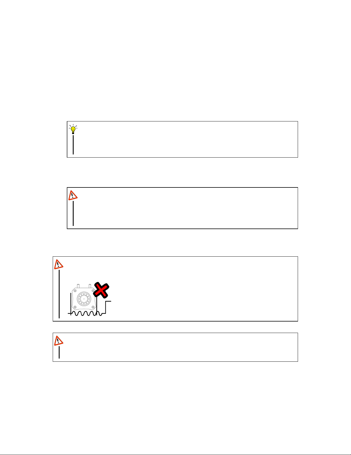
. To prevent damage to the circuit from coolant leakage, please apply/replace
PTFE sealant tape on the thread of the cooling channel headers before attaching
them onto your BEAR and check for leakage carefully.
CAUTION
Refrain from using Copper (II) Sulphate (CuSO4) additive – common trade name
“Nuke Cu” or “Biocide Cu” – due to its tendency to react with metals usually found
in the liquid cooling loop, especially radiators (Zn, Cu, Sn) as well as BEAR (Al)
thus promoting corrosion. Using CuSO4also accelerates visually discouraging
copper tarnishing phenomena.
CAUTION
In the case of regularly liquid cooled applications, please check for leakage in the
liquid cooling loop at least weekly.
CAUTION
To avoid leakage, please do not loosen or tighten the screws on the cooling chan-
nel cap or disassemble the cooling channel cap. The gasket must be replaced
once disassembled.
WARNING
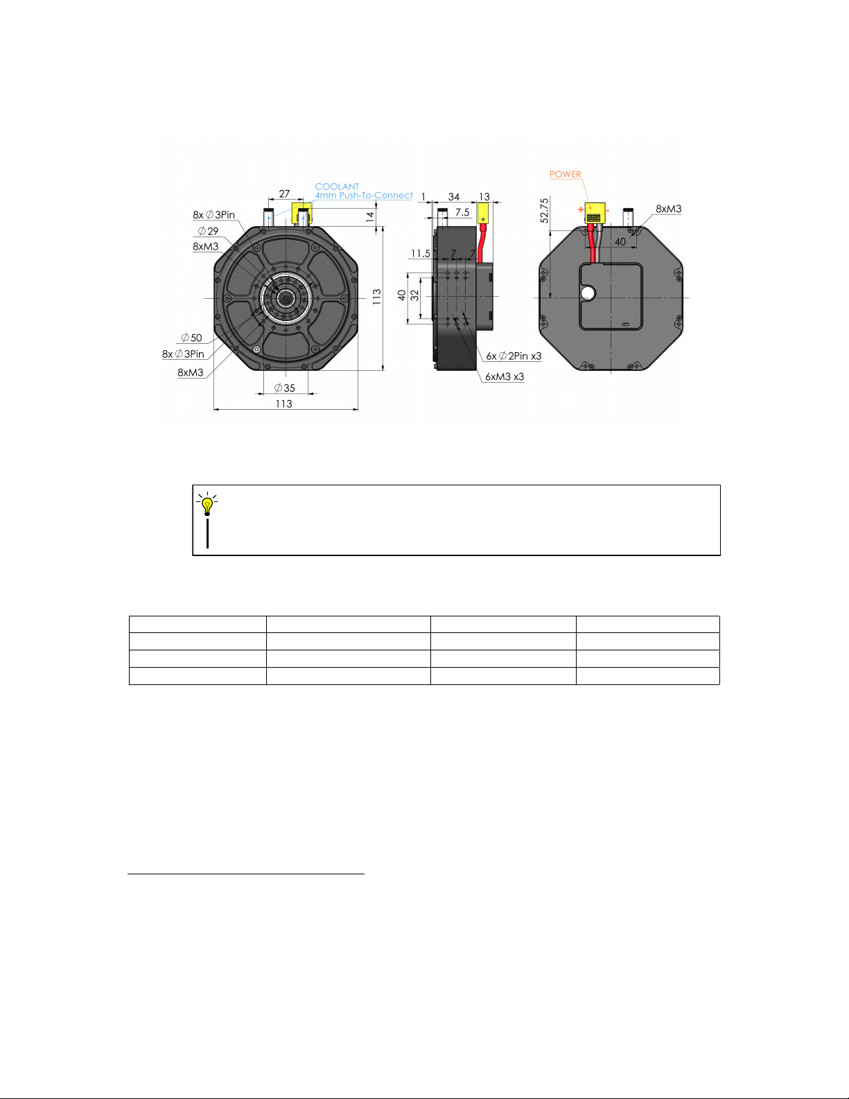
b) Panda BEARTM V2 (PB02)
With the right balance of torque, weight, and form factor, Panda BEAR V2(PB02) is our
most versatile unit. Its excellent dynamic performance and payload capability makes it well
suited for diverse applications ranging from legged mobile robots to service and entertain-
ment robots. The mechanical and electrical as well as the thermal management features are
introduced as following, with the help of figure 2.
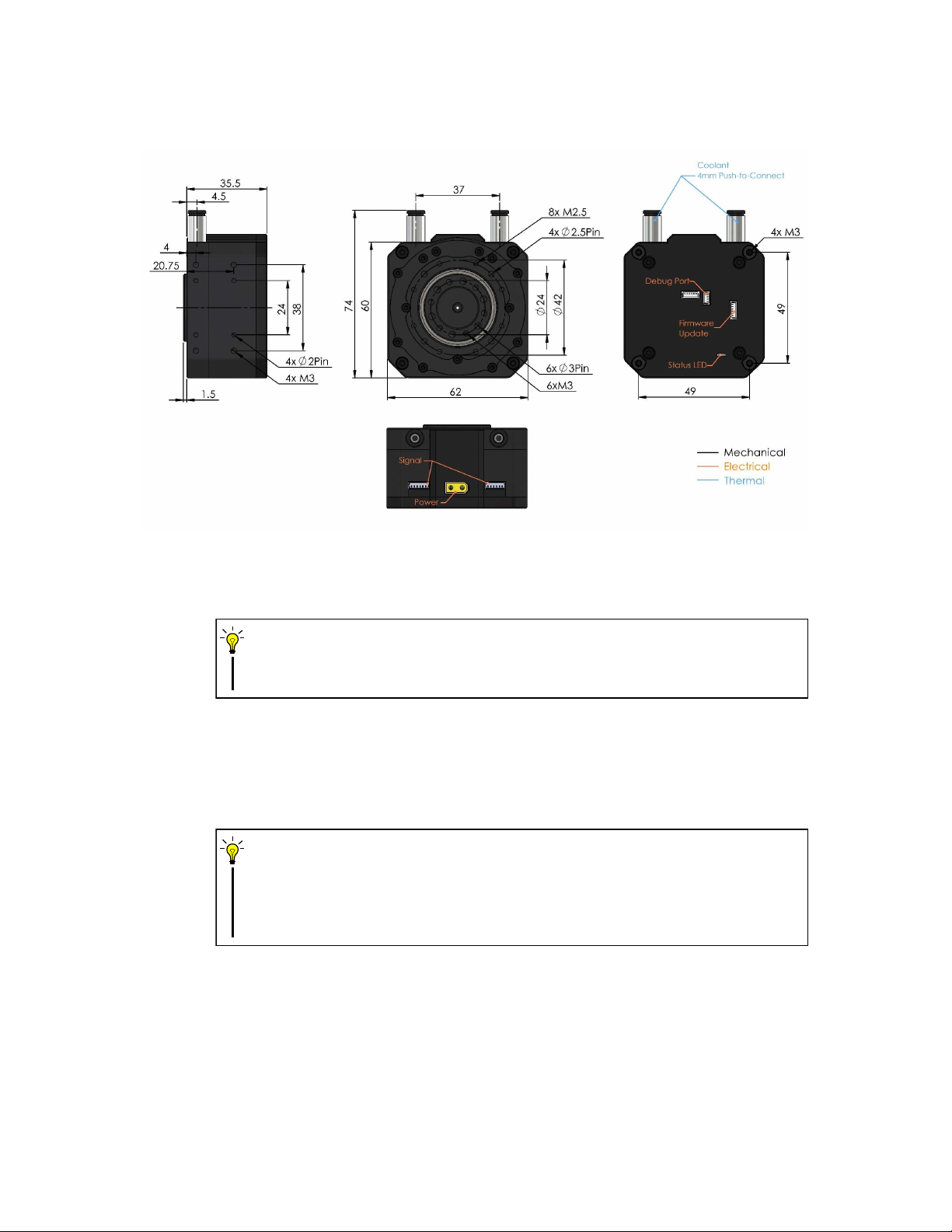
•Mechanical Features The dimensions and locations of mounting features are anno-
tated as in figure 2. There are eight M3 screw holes and eight 3mm pin holes on the
output shaft for locating and connecting the payload. The eight M3 screw holes and
3mm pin holes located on the front side as well as the six M3 screw holes and six 2mm
pin holes on each of the three sides can all be used to locate and mount PB02 to its
application. Besides, there are also eight M3 screw holes on the back that are axisym-
metric about the output shaft, and these eight M3 screw holes can also be used as
mounting points or to mount additional bearings under certain application.
6