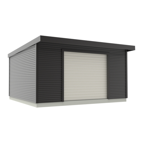
X-METAL 4065 User manual

The Car Garage OWNER'S MANUAL
Metallgarage AUFBAUANLEITUNG
Garage in metallo ISTRUZIONI MONTAGGIO
Cochera de metal INSTRUCCIONES DE MONTAJE
Garage en métal NOTICE DE MONTAGE
EN
DE
IT
ES
FR
EN
DE
IT
ES
FR
4065

880
200
40
17
PART NO. Qty. NO. Qty. NO.PART PART
2
2
1
1
1
1
1
1
1
1
1
1
2
4
4
6
2
2
2
7
1
2
2
1
2
4
2
1
1
1
2
3L
3R
4L
4R
10R
11
13
14
17
18
15
16
10L
19
5L
5R
6L
6R
7
8
9
12R
12L
12
3
7L
7R P4L
P4R
25L
25R
21L
21R
P6R
24
22
23
31
32
33
34
P6L
L1
J4
35
P1
P5
P2
P3
P4
P6
P7
B2
B1
B3
F5
GC
GE
GF
2
2
1
2
2
1
1
8
6
1
4
4
4
2
1
16
2
1
9
2
1
2
1
1
4
2
2
1
100
2
4
4
D1
42
43
J2
J1
B5
J3
40
41
44
45
46
47
48
49
D2
30
29
29-1
36
37
38
39
50
F1
F2
F3
F4
B6
H1
H2
J6
J5
2
2
4
4
4
3
2
1
4
4
1
1
1
1
2
4
1
1
1
1
1
1
2
2
9
2
2
Qty.
1
1
EN PARTS LIST FR LISTE DES ELEMENTS DE STÜCKLISTE
IT LISTA COMPONENTI ES LISTA DE PIEZAS

PRECISE DIMENSION
DIMENSIONS DU GARAGE
ABMESSUNGEN DER GARAGE
DIMENSIONI GARAGE
DIMENSIONES DE LA COCHERA
2
232cm
186cm
300cm
602cm
289cm
212cm
590cm
78cm
187cm
EN
FR
DE
IT
ES

17
18
18
17
15
15
15
16
15
16
15
15
GC
GC
GC
GC
GE
P4L
P4R
P4L
P4R
P4L
P4R
P4L
P4L
P4R
P4L
P4R
P4L
P4R
P4L
19
GE
19
19
19
19
19
19
21L
21L
21R
21R
B3
B2
B1
B3
B1
B2
7L
7R
J4
J4
7
13
14
12
12
14
13
24
24
34
34
32
32
32
32
33
33
33
33
L1
L1
L1
L1
P1
P1
P7
P1
P2
P1
P1
P3
P1
P3
P5
P1
P1
P2
P1
P6
P4
P6R
P6L 9
8
11
9
8
11
10L
10R
12L
22
12R
23
22
12R
6L
6R
1
3
2
1
3
2
31
31
31
31
3L
3R
J1
J1
J1
J1
4L
4R
J2
J2
J2
J2
J3
25L
25R
35
3

30
30
41
40
37
39
38
30 B6
30
D2
D1
D1
B6
B6
H1
J6
B5
42
42
43
43
43
43
29
29-1
29-1
29
29
29-1
29
29-1
5L
5R
B6
B6
B6
B6
B6
B6
48
49
50
50
49
48
44
45
46
47
H2
H2
B5
J5 H1
36
4

5
PART NO. Qty.
F1
12
2 2
3L 1
3R 1
4L 1
4R 1
2
3
J3
J2
J1 4
4
F4
2
Front
3L
3R
1
3
24L
4R
1
3
2
J2
J2
J2
J2
4L
4R
1
3
F1
F4
J2
2
3R
F1
J1
J1
J1
24L
F4
F1
J1
J1
F1
4L
4R
F1
3
1
J3
J3
Veuillez utiliser des gants de protection, certains éléments pouvant être tranchants.
Repérez les pièces concernées, disposez-les comme c'est indiqué sur le schéma et fixez-les avec les vis (F1).
Assurez-vous que la base est parfaitement d'équerre lors du montage.
Des trous supplémentaires existent sur la base. Ils peuvent servir à l'ancrage de votre garage sur votre fondation,
pour une meilleure stabilité dans le temps.
Be careful of the sharp edges, please make sure to use gloves.
Find out the parts listed, well organize the position as showed in the picture and fix the parts by screws(F1).
Make sure the base ina perfect square shape.
Make sure the base bars are assembled in a perfect square. There are extra holes on these base frame, these
can be used tosecure the shed to wooden foundation or concrete pad.
Tragen Sie beim Aufbau Schutzhandschuhe, da einige Elemente scharf sein können.
Suchen Sie sich die erforderlichen Teile heraus, ordnen Sie sie wie auf dem Schema angegeben an und befestigen
Sie sie mit den Schrauben F1. Achten Sie darauf, dass der Bodenrahmen beim Aufbau vollkommen rechtwinklig ist.
Es sind zusätzliche Löcher im Bodenrahmen vorhanden, die zur Verankerung Ihrer Garage am Fundament genutzt
werden können, um eine bessere Stabilität zu gewährleisten.
Utilizza dei guanti di protezione: alcuni oggetti possono essere taglienti.
Trova gli oggetti in questione, disponili in base a come è indicato sullo schela e fissali con delle viti (F1).
Assicurati che la base sia perfettamente quadrata durante il montaggio. Sulla base ci sono dei fori aggiuntivi;
gli stessi possono servire al fissaggio del garage sulla tua base per una maggiore stabilità nel tempo.
Utilice guantes de protección, algunas piezas pueden cortar.
Localiza las partes en cuestión, colócalas tal y como se muestra en el boceto y fíjalas con los tornillos (F1).
Asegúrate de que la base sea perfectamente cuadrada al montarla.
Existen huecos adicionales en la base que se pueden usar para anclar la cochera en la base,
para una mejor su estabilidad.
EN
FR
DE
IT
ES
BASE FRAME ASSEMBLY
ASSEMBLAGE DE LA BASE
MONTAGE DES BODENRAHMENS
ASSEMBLAGGIO BASE
MONTAJE DE LA BASE
EN
FR
DE
IT
ES
6
P6R
P1 9
2
P3 2
P4 1
P5 1
P6 1
1
P6L
PART NO. Qty.
F1
12L 1
12R 2
22 2
23 1
6L 1
1
6R
P2
1
P7 1
Attention : NE PAS PROCEDER AU MONTAGE LORSQU'IL Y A DU VENT.
Sortez tous les éléments listés des cartons. Placez les panneaux sur la base, un par un et
fixez l'armature du milieu de panneaux de manière synchonisée, pour éviter l'éffondrement
des panneaux.
Warning: DO NOT COMPLETE THIS STEP ON WINDY DAYS.
Find out the parts listed. Place panels on the base one by one, fix the bars on the middle
of wall synchronously to avoid the collapse of the wall.
Achtung: BAUEN SIE DAS PRODUKT NICHT BEI WIND AUF.
Nehmen Sie alle aufgelisteten Teile aus dem Paket. Positionieren sie die Paneele auf dem
Bodenrahmen und befestigen Sie das Gestell von der Mitte der Mitte der Paneele aus, um
ein Zusammenstürzen zu vermeiden.
Attenzione: NON PROCEDERE ALL'ASSEMBLAGGIO IN CASO DI VENTO.
Estrai tutti gli elementi dalla confezione. Disponi i pannelli sulla base uno per volta e fissa la
struttura centrale per evitare il cedimento dei pannelli.
Precaución: NO MONTAR CUANDO HAYA VIENTO.
Saca todos los artículos enumerados de las cajas. Coloca los paneles en la base, uno por
uno, y fija la estructura central para evitar que los paneles se derrumben.
EN
FR
DE
IT
ES
SIDE WALL ASSEMBLY
ASSEMBLAGE DES PAROIS DE COTES
MONTAGE DER SEITENWÄNDE
MONTAGGIO PARETI LATERALI
MONTAJE DE LAS PAREDES LATERALES
EN
FR
DE
IT
ES
EN
FR
DE
IT
ES
Note: Conservez un espace de 7-8cm entre chaque barre
côtés gauche et droit, tels qu'indiqué sur le schéma.
Anmerkung: Lassen Sie wie auf dem Schema angegeben
7-8cm Platz zwischen jeder Verstrebung links und rechts.
Nota: Lascia uno spazio di 7-8 cm tra ciscuna barra nei lati
sinistro e destro così come indicato sullo schema.
Nota: Deja un espacio de 7-8 cm entre cada barra en los
lados izquierdo y derecho tal como se muestra en el boceto.
Note: Keep 7-8cm space between each enhanced bars
left and right sides according to the diagram.
P1
P2 P1 P7
P1
P5
P1
P3
P3
P4
P6 P1 P2
P1
P6L
P6R
12L
12R
12R
6L
6R
22
22
23
F1
F1
3L
12R
22 P2
12L
22
22
12R
12R
6L
6R
23
6R
6L
P1
P1
P1

7
Well Well place each top bars as showing and fix by screws and washers (F1).
Placez correctement chaque barre supérieure, et fixez-les avec des vis et des rondelles (F1).
Platzieren Sie jede obere Leiste und befestigen Sie sie mit den Schrauben und Unterlegscheiben (F1).
Posiziona correttamente ciascuna barra superiore e fissala con viti e rondelle (F1).
Coloca correctamente cada barra superior, y asegúrala con tornillos y arandelas (F1).
PART NO. Qty.
2
F1
2
1
9
2
1
8
11
10L
10R
TOP FRAME ASSEMBLY
ASSEMBLAGE DE L'ARMATURE SUPERIEURE
MONTAGE DES OBEREN GESTELLS
MONTAGGIO STRUTTURA SUPERIORE
MONTAJE DELA ESTRUCTURA SUPERIOR
EN
FR
DE
IT
ES
EN
FR
DE
IT
ES
9
8
11
11
8
9
F1
10L
10R
11
P6R
F1
11
8
P1
10R
10L

8
PART NO. Qty.
4
F5
4
16
31
2
4
24
32
33
L1
31
31
33 33
32
32
24
L1
L1 L1
L1
F5
F5
24
32
32
31
L1
33
SUPPORTING FRAME ASSEMBLY-1
ASSEMBLAGE DES BARRES DE SUPPORT-1
MONTAGE DER VERSTREBUNGEN-1
ASSEMBLAGGIO BARRE DI SUPPORTO-1
MONTAJE DE LAS BARRAS DE SOPORTE-1
EN
FR
DE
IT
ES
EN
FR
DE
IT
ES
Sortez toutes les pièces listées, et reliez-les comme indiqué sur le schéma. Fixez-les avec les vis F5.
Rappelez-vous que 2 sets d'armature de support nécessitent d'être assemblés.
Nehmen Sie alle aufgelisteten Teile heraus und befestigen Sie sie wie auf dem Schema angegeben mit den
Schrauben F5 aneinander. Denken Sie daran, dass 2 Sets der Verstrebungen zusammengebaut werden müssen.
Estrai tutti gli oggetti indicati e uniscili come indicato sullo schema. Fissali con le viti F5.
Ricorda che due set di telai di supporto necessitano di essere assemblati.
Saca todas las piezas enumeradas y conéctalas tal y como se muestra en el boceto.
Asegúralas con los tornillos F5. Recuerda que se deben ensamblar 2 conjuntos de marcos de soporte.
Find out all parts listed, link up one by one as showing, fasten by F5.
Remember 2 sets of supporting frames need to be assembled.

9
PART NO. Qty.
F2
F2
P7
P2
P2
P6
SUPPORTING FRAME ASSEMBLY-2
ASSEMBLAGE DES BARRES DE SUPPORT-2
MONTAGE DER VERSTREBUNGEN-2
ASSEMBLAGGIO BARRE DI SUPPORTO-2
MONTAJE DE LAS BARRAS DE SOPORTE-2
EN
FR
DE
IT
ES
EN
FR
DE
IT
ES
Placez l'armature de support correctement (voir l'espace de 7-8cm mentionné dans la section "Assemblage des parois"),
et attachez les avec les vis (F2).
Platzieren Sie die Verstrebungen (siehe in "Montage der Wände" erwähnten Abstand von 7-8cm) und befestigen
Sie sie mit den Schrauben F2.
Posiziona il telaio di supporto correttamente (vedi lo spazio di 7-8 cm richiamato nella parte "Assemblaggio pareti")
e uniscili con le viti (F2).
Coloca correctamente el marco de soporte (ve el espacio de 7-8 cm mencionado en la sección "Montaje de las
paredes laterales") y únelo con los tornillos (F2).
Place the supporting frame rightly (see the 7-8cm space mentioned in wall installation), fix them to
panels by screw (F2)

10
2120mm
7
F1
P6L
P6R
5L 5R
F1
5L
3L 5R
3R
F1
J4
7L
P6L
5L&5R
B6
F3
PART NO. Qty.
1
1
5R
15L
7
J4 2
F1
1
1
7L
7R
F3
B6
PART NO. Qty.
6
DOOR FRAME ASSEMBLY
ASSEMBLAGE DE LA PORTE
MONTAGE DER TÜR
ASSEMBLAGGIO PORTA
MONTAJE DE LA PUERTA
EN
FR
DE
IT
ES

11
PART NO. Qty.
F2
21L 2
21R 2
B1 2
B2 2
B3 4
GF 4
F1
Note: screw each hole
Note: une vis dans chaque trou
Anmerkung: eine Schraube für jedes Loch
Nota: una vite per ciascun foro
Nota: atornillar cada hueco
GABLE ASSEMBLY
ASSEMBLAGE DU TRIANGLE
MONTAGE DES GIEBELDREIECKS
ASSEMBLAGGIO TRIANGOLO
MONTAJE DEL TRIÁNGULO
EN
FR
DE
IT
ES
EN
FR
DE
IT
ES
F2
B3
21R
F2
21L
21R
B2 21R
21L
B1
GF
F2
21R
10L
F1

12
13
12
14
13
12
14
F2 13
14
21R
21L
21R
B2
PART NO. Qty.
4
4
13
4
12
14
F2
F2
F2
12
14
Frame 1
Frame 2
Frame 3
Frame 4
13 14
Frame 1
Frame 2
Frame 3
Frame 4
ROOF FRAME ASSEMBLY
ASSEMBLAGE DE L'ARMATURE DE TOIT
MONTAGE DES DACHGESTELLS
ASSEMBLAGGIO TELAIO TETTO
MONTAJE DEL MARCO DEL TECHO
EN
FR
DE
IT
ES

13
F1
F1
TOP
PART NO. Qty.
F1
TOP BEAM REINFORCEMENT-1
RENFORCEMENT DU FAITAGE-1
VERSTÄRKUNG DES FIRSTES-1
RAFFORZAMENTO LINEA DI COLMO-1
REFUERZO DE LA CUMBRERA-1
EN
FR
DE
IT
ES

14
34
34
32 32
F5 F5
24
PART NO. Qty.
2
F5
34
TOP BEAM REINFORCEMENT-2
RENFORCEMENT DU FAITAGE-2
VERSTÄRKUNG DES FIRSTES-2
RAFFORZAMENTO LINEA DI COLMO-2
REFUERZO DE LA CUMBRERA-2
EN
FR
DE
IT
ES

P4L
P4L
P4R
P4R
P4R
P4R
P4L
P4L
F1
15
P4R
P4L
P4L
P4R
P4L P4L
PART NO. Qty.
P4L 8
P4R 6
F1
Note: Screw each hole in panels.
Note: une vis dans chaque trou des panneaux.
Anmerkung: eine Schraube in jedes Loch der Paneele.
Nota: una vite per ciascun foro dei pannelli.
Nota: atornillar cada hueco de los paneles.
ROOF PANEL ASSEMBLY
ASSEMBLAGE DES PANNEAUX DE TOIT
MONTAGE DER DACHPANEELE
ASSEMBLAGGIO PARETI TETTO
MONTAJE DE LOS PANELES DEL TECHO
EN
FR
DE
IT
ES
EN
FR
DE
IT
ES

18 2
GC 4
PART NO. Qty.
17 2
15 6
16 2
F1
16
Note: Screw each hole on the edge of roof bar.
Note: une vis dans chaque trou de la barre de toit.
Anmerkung: eine Schraube in jedes Loch der Dachleiste.
Nota: una vite per ciascun foro della barra del tetto.
Nota: atornillar cada hueco de la barra del techo.
F1
15
16
F1
17
1
5
GC
18 17
17
18
15
15
15
15
18
17
17 18
16
16
15
15
FLASHING ASSEMBLY
ASSEMBLAGE DES RIVES
MONTAGE DER ZIERLEISTEN
ASSEMBLAGGIO LATI
MONTAJE DE LOS BORDES
EN
FR
DE
IT
ES
EN
FR
DE
IT
ES

25L 25R
25L
F1
F2
25L
F1 GE
19
19
29
F1
17
F1
25L
J6
35
PART NO. Qty.
2
719
GE
F1
125R
125L
F2
1
J6
PART NO. Qty.
1
35 1

18
PART NO. Qty.
43
29
29-1
H2
F1
36
2
2
2
2
1
F1
F1
F1
F1
F1
F1
F1
43
29-1
29
29
H2
29-1
H2
36
DOOR ASSEMBLY-1
ASSEMBLAGE DE LA PORTE-1
MONTAGE DER TÜR-1
ASSEMBLAGGIO PORTA-1
MONTAJE DE LA PUERTA-1
EN
FR
DE
IT
ES

19
PART NO. Qty.
1
F1
45
F2
50 1
D1 1
D1
50
Ⅰ
Ⅱ
45
F1
F1
F1
F2
F2
F2
F2
F2
F1
DOOR ASSEMBLY-2
ASSEMBLAGE DE LA PORTE-2
MONTAGE DER TÜR-2
ASSEMBLAGGIO PORTA-2
MONTAJE DE LA PUERTA-2
EN
FR
DE
IT
ES
Popular Outdoor Storage manuals by other brands

Palmako
Palmako Rasmus FR44-3857-6 installation manual

Arrow Storage Products
Arrow Storage Products EZEE SHED EZ107CCCR Owner's manual & assembly guide

Lifetime
Lifetime 60040 Assembly instructions

EPCOM Industrial
EPCOM Industrial GT003G user manual

Hornbach
Hornbach 74665 Building instructions

Handy Home Products
Handy Home Products OCOEE Assembly manual

garofalo
garofalo TUSCANY EVO 100.1P user manual

SmartStore
SmartStore SM2015 Assembly instructions

Mercia Garden Products
Mercia Garden Products 01GRA0301-V3 quick start guide

Duratuf
Duratuf GL65 Assembly instructions

Select
Select NOAM E9641 Assembly manual

Biohort
Biohort WoodStock 230 Assembly instructions