XCI TSH-2 TrueTouch User manual

5 YEAR
LIMITED
WARRANTY*
Innovation made simple...SM
INSTRUCTION MANUAL
TSH-2 3 HEATING + 2 COOLING
HUMIDITY + DUAL FUEL READY

WIRELESS OUTDOOR TEMPERATURE
TRANSMITTER AND RECEIVER KIT
Part No. TOS
Wireless Outdoor Temperature
Transmitter and Receiver Kit Includes:
Transmitter
Antenna
Receiver Module
2 AA Batteries
Accurately displays
current Outdoor Temperature
and enables Dual Fuel capability
on the TrueTouch™ Thermostat

TABLE OF CONTENTS
5
GLOSSARY OF TERMS ..................................................................................................6
SELECTING A LOCATION...............................................................................................7
MOUNTING THERMOSTAT TO THE WALL ...................................................................8
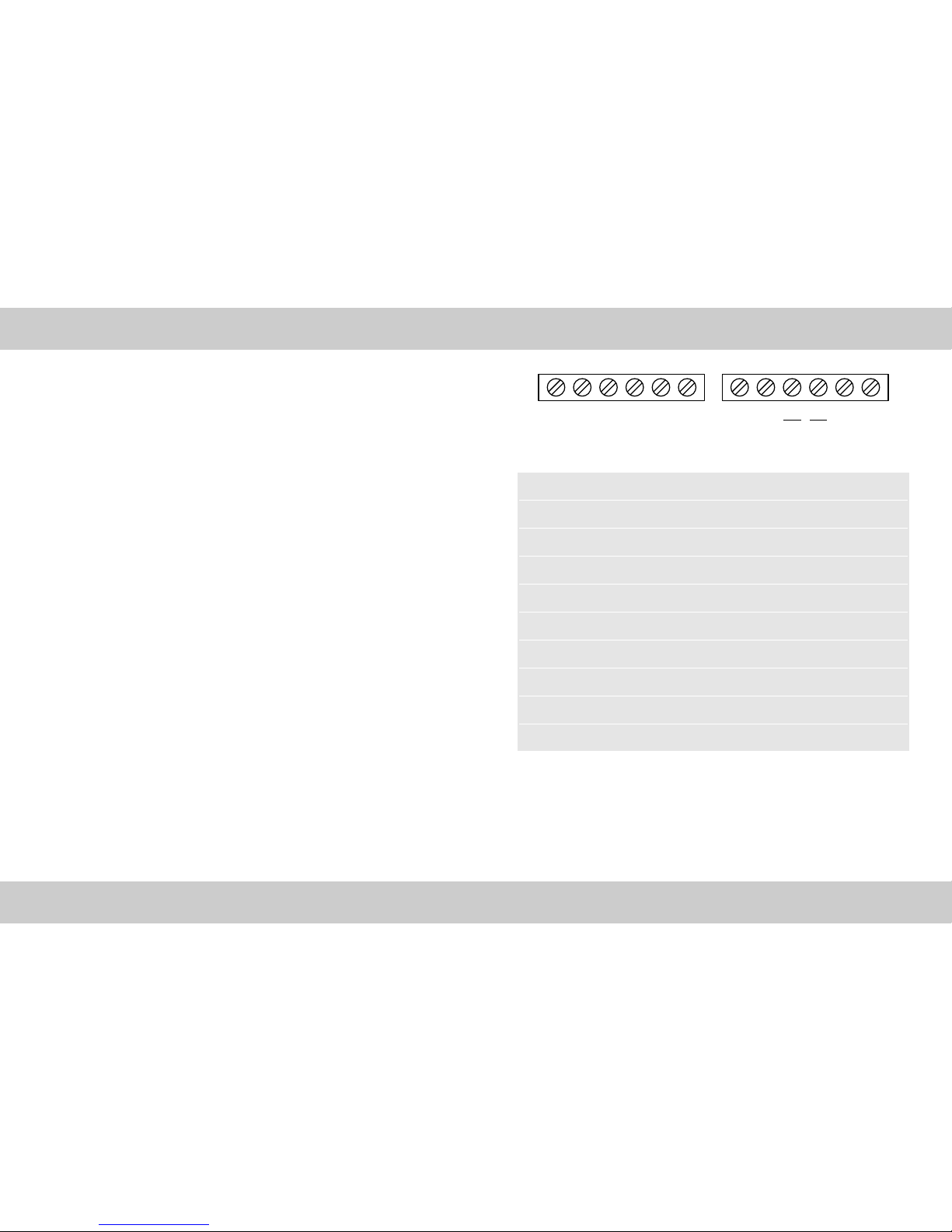
WIRING LEGEND...........................................................................................................9
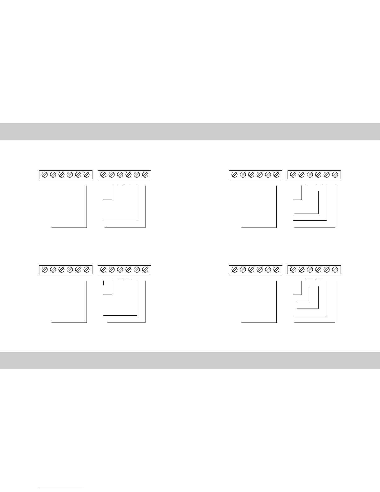
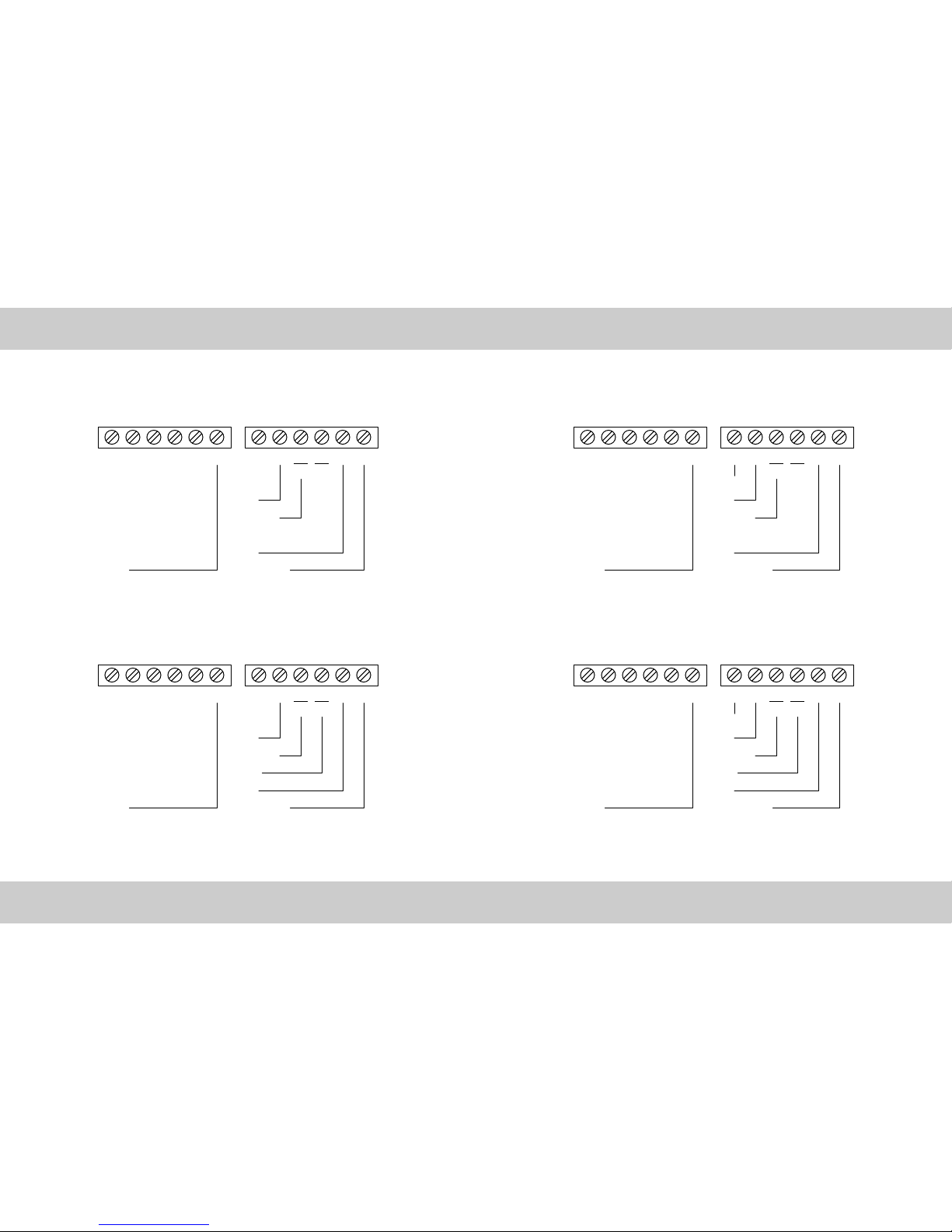
WIRING DIAGRAMS ...................................................................................................10
HOME SCREEN............................................................................................................16
CONTROL SCREEN ......................................................................................................17
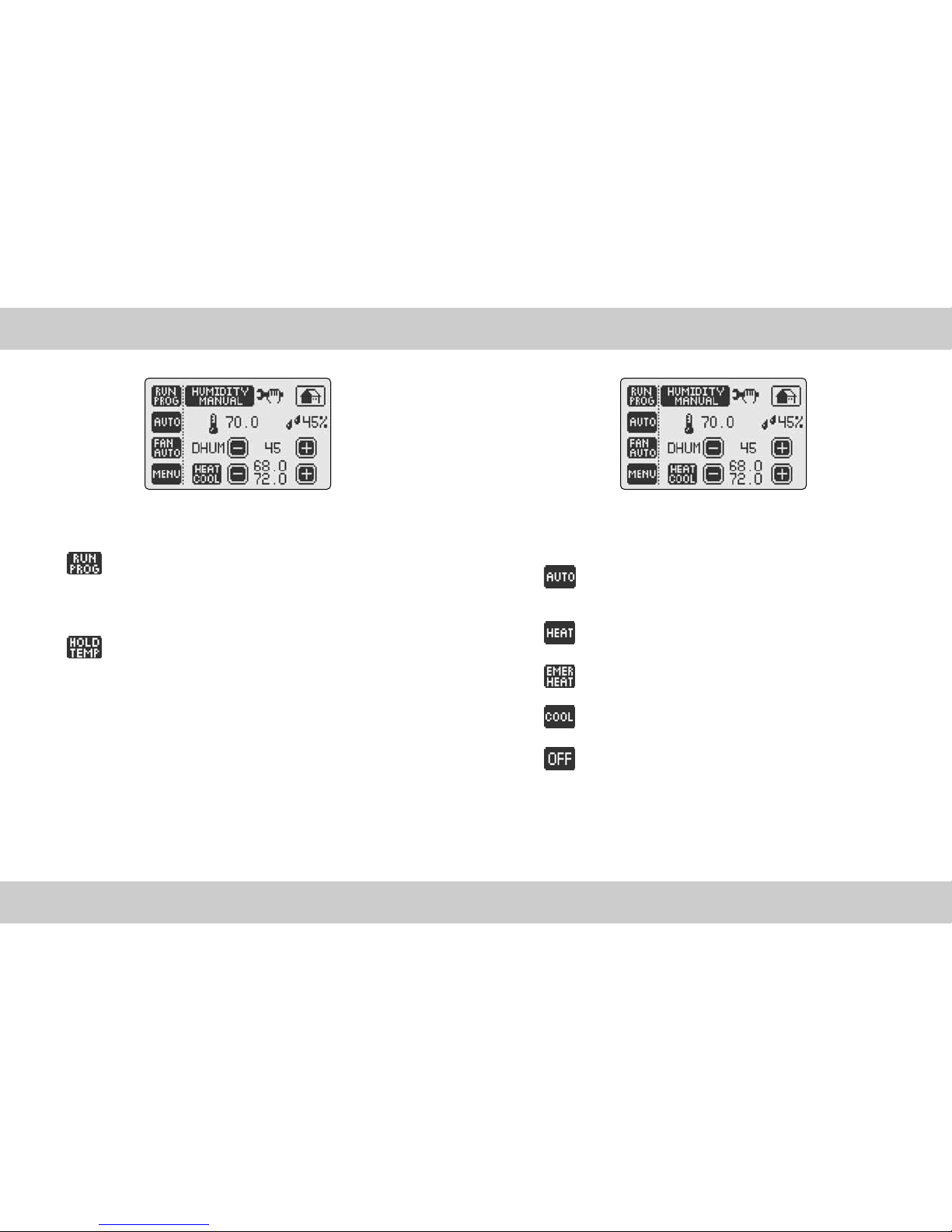
THERMOSTAT OPERATION MODES ...........................................................................18
TEMPERATURE CONTROL MODES .............................................................................19
AUTOMATIC HUMIDITY CONTROL .............................................................................20
HUMIDIFY AND HUMIDITY SETPOINT........................................................................21
DE-HUMIDIFY AND HUMIDITY SETPOINT ..................................................................22
FAN OPERATION MODES............................................................................................23
MENU SCREEN ...........................................................................................................24
DATE AND TIME SETTINGS........................................................................................26
PROGRAM SETTINGS..................................................................................................27
ENERGY WATCH.........................................................................................................28
SET SCREEN OPTIONS................................................................................................29
VACATION MODE .......................................................................................................30
FILTER MONITOR ........................................................................................................31
ADVANCED SETTINGS - FEATURES SETTINGS ..........................................................32
ADVANCED SETTINGS - SYSTEM CONFIGURATION..................................................34
ADVANCED SETTINGS - DUAL FUEL SWITCH ............................................................35
ADVANCED SETTINGS - DIFFERENTIAL SETTINGS ....................................................36
ADVANCED SETTINGS - TIMER FEATURE ..................................................................37
ADVANCED SETTINGS - HEAT PUMP ........................................................................38
ADVANCED SETTINGS - HUMIDITY SETTINGS ..........................................................39
ADVANCED SETTINGS - CALIBRATION ......................................................................42
ADVANCED SETTINGS - CALIBRATION ......................................................................43
SIMPLE THERMOSTAT MODE.....................................................................................44
TROUBLESHOOTING ...................................................................................................45
IMPORTANT NOTICE ..................................................................................................46
WARRANTY ................................................................................................................47

SELECTING A LOCATION
7
Install your TrueTouch™ thermostat approximately 5 feet (1.5 meters) above the
floor in an area with good air circulation.
Avoid the following locations:
• Hot or cold air from ducts
• Radiant heat for appliances or sun such as a skylight
• Unheated or uncooled areas: for example an outside wall behind the thermostat.
• Ensure that there is no furniture directly below or beside the thermostat.
GLOSSARY OF TERMS
6
CYCLE RATE - Cycle rate is the frequency that heating or cooling equipment is turned
on during a certain period of time. Cycle rate is often given in units of cycles per hour
(CPH).
DEHUMIDIFY - The process of removing moisture from the air.
DEHUMIDIFIER - Device used to remove moisture from the air.
DIFFERENTIAL - Differential is defined as the difference between the cut-in and
cut-out points as measured at the thermostat under specified operating conditions. For
example, if the thermostat turns the heating equipment on at 70 degrees F and turns the
heating equipment off at 74 degrees F, then the differential is 4 degrees F.
HUMIDIFIER - A device used to add moisture to a space.
HUMIDISTAT - A control which is operates the humidifier and is affected by changing
humidity.
HUMIDITY - Moisture in the air.
PROGRAMMABLE THERMOSTAT - A thermostat with the capability of automatically
adjusting temperature set point to pre-selected settings at pre-selected times.
SETBACK - The automatic alteration of the thermostat control point(s) by means other
than manually changing the temperature set point.
SET POINT - The desired temperature setting on an electromechanical or electronic
thermostat.

WIRING LEGEND
9
MOUNTING THERMOSTAT TO THE WALL
8
1. Make sure to turn off the power supply located at the electrical service panel.
All heating and cooling units should be OFF.
2. Separate the backplate from the thermostat by grasping the unit firmly at the
bottom lip and pulling gently until the two piece are apart.
3. Align the backplate to the wall.
4. Mark the three locations for drilling the 3/16” holes required for the plastic
screw anchors.
5. Remove the backplate and drill the three 3/16” holes in these locations.
6. Insert the plastic gyproc screws and ensure that they are snug in the wall.
7. Securely mount the backplate to the wall with the 3 supplied screws.
8. Make the appropriate wire connections based on the specifications of the
household HVAC unit(s). Please refer to Wiring Table to determine the appropriate
wire connections.
9. Place the thermostat on the backplate by firmly but gently from the top aligning
the pins with the screw terminals.
10. Turn on the electricity at the electrical service panel.
RC DH H C Y2 RH W2
OB
W1
EH
GY1
TERMINAL EQUIPMENT STANDARD COLOR
Y1 Cool 1 or Compressor (HP) Yellow
G Fan Green
W1/EH Heat 1 or Emergency Heat (HP) White
W2/OB Reversing Valve or Heat 2 Orange
RH 24VAC Heat Red
Y2 Cool 2 or Compressor 2 (HP) Black
C 24VAC Common Blue
H Humidifier Unknown
DH Dehumidifier Unknown
RC 24VAC Cool Unknown
NOTE: The above colors are semi-standard in HVAC industry.
The wiring should be confirmed on both ends before installation.

WIRING DIAGRAMS
11
HEAT 2
HEAT 1
24V
FAN
COMMON
ONE STAGE COOL AND TWO STAGE HEAT
RC DH H C Y2 RH W2
OB
W1
EH
GY1
COOL
HEAT
24V
FAN
COMMON
ONE STAGE COOL AND ONE STAGE HEAT
RC DH H C Y2 RH W2
OB
W1
EH
GY1
COOL
WIRING DIAGRAMS
10
ONE STAGE COOL
24V
FAN
COOL
COMMON
RC DH H C Y2 RH W2
OB
W1
EH
GY1
COOL 2
24V
FAN
COOL 1
COMMON
TWO STAGE COOL
RC DH H C Y2 RH W2
OB
W1
EH
GY1

WIRING DIAGRAMS
13
WIRING DIAGRAMS
12
HEAT
REV VALVE
24V
FAN
COMPRESSORCOMMON
ONE STAGE HEAT PUMP WITH AUX/EMERGENCY HEAT
RC DH H C Y2 RH W2
OB
W1
EH
GY1
REV VALVE
24V
FAN
COMPRESSORCOMMON
ONE STAGE HEAT PUMP
RC DH H C Y2 RH W2
OB
W1
EH
GY1
REV VALVE
24V
FAN
COMPRESSOR 1COMMON
TWO STAGE HEAT PUMP
COMPRESSOR 2
RC DH H C Y2 RH W2
OB
W1
EH
GY1
HEAT
REV VALVE
24V
FAN
COMPRESSOR 1COMMON
TWO STAGE HEAT PUMP WITH AUX/EMERGENCY HEAT
COMPRESSOR 2
RC DH H C Y2 RH W2
OB
W1
EH
GY1

WIRING DIAGRAMS
15
WIRING DIAGRAMS
14
HEAT
TRANSFORMER
COOL
TRANSFORMER
CUT
TWO TRANSFORMERS
RC DH H C Y2 RH W2
OB
W1
EH
GY1
HEAT
TRANSFORMER
ONE TRANSFORMER
RC DH H C Y2 RH W2
OB
W1
EH
GY1
HUMIDIFIER WITHOUT TRANSFORMER
RC DH H C Y2 RH W2
OB
W1
EH
GY1
24V
HUMIDIFIER 2nd WIRE
HUMIDIFIER 1st WIRE
HEAT 2
HEAT 1
24V
FAN
COMMON
TWO STAGE COOL AND TWO STAGE HEAT
RC DH H C Y2 RH W2
OB
W1
EH
GY1
COOL 2
COOL 1

Current Room
Temperature
Current Room Humidity
Current Outdoor
Temperature
Current Thermostat Operation
Mode
Current Temperature
Control Mode
Current Fan
Operation Mode
Fan Operation Indicator
Vacation Mode Indicator
Security Indicator
Heat setpoint
Cool setpoint
Date
Time
Change the Temperature Setpoint(s) using -and +buttons. In
AUTO MODE toggle the HEAT/COOL button (HEAT or COOL will
flash once selected), then raise or lower setpoints as desired.
Change the Humidity Setpoint using -and +buttons.
Select the Thermostat Operation Mode by toggling thermostat
operation mode button.
Select the Temperature Control Mode by
toggling the temperature control mode button.
Select the Fan Operation Mode by toggling the fan oper-
ation mode button.
Select the Humidity Control mode by toggling
the humidity control mode button.1
Access MENU SCREEN to enter into all thermostat features and settings.
Displays Installer Message to review important information.
CONTROL SCREEN
17
>> To access the CONTROL SCREEN, simply touch the HOME SCREEN Screen…
>> From the CONTROL SCREEN, you can:
HOME SCREEN
16
>> To return to the HOME SCREEN, simply touch icon at any time!
>> The HOME SCREEN displays the following information:
1 Available only in combination with WIRELESS OUTDOOR TEMPERATURE TRANSMITTER AND RECEIVER KIT (90064)

TEMPERATURE CONTROL MODES
19
>> Based on your HVAC equipment TrueTouch™ thermostat can operate in the
following temperature control modes - AUTO or HEAT or EMERGENCY HEAT
or COOL or OFF.
AUTO - Keeps the room temperature between the selected HEAT
and COOL setpoints by using both the cooling and heating HVAC
units.
HEAT - Only turns on the heating units to regulate room temperature.
EMERGENCY HEAT - Enables the emergency heat (if required).
COOL - Only turns on the air conditioning to regulate room temperature.
OFF - Will not control temperature. The thermostat will continue
to display the current room temperature, current room humidity
and outdoor temperature.
THERMOSTAT OPERATION MODES
18
>> TrueTouch™ thermostat can operate in PROGRAM MODE or can HOLD a
fixed temperature.
RUN PROGRAM: Initiates the 7-day Programmable Temperature
Control Program with 4 independent events per day. To set up a
custom temperature control program with customizable
Temperature Setpoint and Fan operation mode, refer to Section
PROGRAM SETTINGS (page 27).
HOLD TEMPERATURE: Regulates the room temperature as
determined by the selected Temperature Setpoint.

HUMIDIFY AND HUMIDITY SETPOINT
21
>> HUMIDIFY SETPOINT: Allows you to increase and maintain the relative humidity at
a specific setpoint. Once you choose HUMIDIFY follow these easy steps:
• The HUM setpoint with -and +icons allow you to lower and raise your setpoint.
*Example of the typical use of the Humidify Function: If the current humidity is 30%
your TrueTouch™ thermostat will initiate the humidifier to function until Setpoint
50% is reached. In order to humidify you must set the humidity setpoint above the
current humidity.
AUTOMATIC HUMIDITY CONTROL
20
>> In order to reduce condensation, humidity must be controlled and air move-
ment must be generated. As the exterior temperature drops, the humidity
level needs to decrease if condensation is to be controlled.
HUMIDITY AUTO: TrueTouch™ thermostat will automatical-
ly adjusts the humidity set point based on the current indoor
temperature and humidity as well as the current outdoor tem-
perature in order to maintain a maximum comfort level and
eliminate condensation. The automatic humidity setpoint is
determined according to the following standard humidity table.1
Setpoint Outdoor Temp in °C Outdoor Temp in °F
15% -29 -20
20% -24 -10
25% -18 0
30% -12 10
35% -7 20
40% -7 -20
HUMIDITY MANUAL: The user selects the humidity setpoint.
1 Available only in combination with WIRELESS OUTDOOR TEMPERATURE TRANSMITTER AND RECEIVER KIT (90064)

FAN OPERATION MODES
23
DE-HUMIDIFY AND HUMIDITY SETPOINT
22
>> DE-HUMIDIFY SETPOINT: Allows you to reduce and maintain the relative humidity at
a specific setpoint.
>> Please note that this feature functions in the COOL Mode only. Your TrueTouch™
Thermostat must be configured to control a cooling unit such as an air conditioner
of heat pump. Once you choose De-Humidify follow these easy steps:
• The DH SETPOINT with -and +icons allow you to lower and raise your setpoint
*Example of typical use of the De-Humidify function: In order to de-humidify you must
set the de-humidify setpoint below the current relative humidity. Your TrueTouch™
will both lower and regulate temperature to the cooling setpoint while monitoring and
lowering the room humidity.
Since the De-Humidify feature uses the COOL Function of your Air Conditioner or Heat
Pump, your TrueTouch™ thermostat will turn off the air conditioning if either the dehu-
midifier setpoint or temperature setpoint is reached - which ever comes first.
>> TrueTouch™ thermostat can operate the fan in one of the following three modes:
FAN AUTO: The fan runs only when there is a demand for heating
or cooling.
FAN ON: The fan runs continuously
FAN INTERMITTENT: The fan runs 10 minutes per 1/2 hour
providing a convenient way to improve air quality and save energy.
When the fan is running, the animated fan icon will
appear on the HOME SCREEN.

MENU SCREEN
Select HUMIDIFY or DE-HUMIDIFY
Control Mode by toggling the humidity
control mode button.
HUMIDIFY increases and maintains the relative humidity of the
room at a humidity setpoint selected on the CONTROL SCREEN.
DE-HUMIDIFY reduces and maintains the relative humidity of the
room at a humidity setpoint selected on the CONTROL SCREEN.
Please note that DE-HUMIDIFY feature functions only in COOL mode. TrueTouch™ ther-
mostat will regulate both the room temperature and the room humidity at the same
time. If DE-HUMIDIFY setpoint reached before the temperature COOL setpoint, the air
conditioning will turn off before the temperature setpoint is reached. This feature has
been specially designed to save energy without compromising the comfort.
Access ADVANCED SETTINGS to configure the thermostat.
To access the ADVANCED SETTINGS, hold the ADVANCED SET-
TINGS button for 5 seconds. The therostat will continuously beep for 5 seconds to indi-
cate that you are in the process of entering this feature.
!CAUTION Altering the system properties in the ADVANCED SETTINGS may
affect the performance of the HVAC system and should be performed only by
a qualified installer.
25
MENU SCREEN
24
>> To access the MENU SCREEN, simply touch MENU from the CONTROL SCREEN.
>> From the MENU page, you can:
Access DATE AND TIME SETTINGS to enter the accurate date
and time
Access PROGRAM SETTINGS to pre-program temperature
changes during each day of the week.
Access ENERGY WATCH to display kWh consumption and the
dollar cost of operating the HVAC System
CLEAN SCREEN places the touch screen in a sleep mode for 15
seconds which allows you to wipe the screen with a dampened cloth.
Access the SET SCREEN menu to change screen properties.
Access VACATION SETTINGS to activate the VACATION MODE
Access FILTER MONITOR to review days of "fan run time."

27
PROGRAM SETTINGS
PROGRAM SETTINGS feature allows you to easily and quickly
program daily temperature changes to fit your lifestyle and reduce
energy consumption. You can customize the program for each
day of the week with 4 independent temperature and fan oper-
ation settings per day. To setup your program:
Select the DAY OF THE WEEK
Select the EVENT NUMBER by toggling
the Event Number button
Choose desired FAN OPERATION
MODE by fan operation mode button.
Enter the event START TIME with
Hour/Minute and AM/PM buttons
Choose desired TEMPERATURE SET-
POINT with -and +buttons
Select the next event and repeat the
steps described above. Once finished,
select the next day of the week that you
would like to program. The thermostat will
prompt you to copy the settings. Repeat
steps to program other days of the week.
26
DATE AND TIME SETTINGS
Select the 12 OR 24 HOUR CLOCK display
by pushing the corresponding button.
Set the TIME by togggling hour, minute
and AM/PM buttons.
Set the DATE by toggling Month, Day and
Year buttons.

29
SET SCREEN OPTIONS
•BACKLIGHT: Select between automatic and permanent backlight for the screen.
AUTO: The screen back-light will come on only when you touch
the screen.
ON: Screen will constantly be back-lit.
•REVERSE: Select the positive or negative screen display.
ON: Negative Display (Dark Background)
OFF: Positive Display (Light Background)
•NIGHT REVERSE: changes the touch screen background at night for improved
display under low-lighting conditions. Select between:
ON: the screen automatically reverses the background at 9PM
and returns to the normal display at 6:00AM .
OFF: screen background is determined by REVERSE function.
•CONTRAST: Toggle the screen contrast settings button (1-11) to select the screen con-
trast that suits best your thermostat surroundings. XCI recommends the setting of 7.
28
ENERGY WATCH
ENERGY WATCH feature provides a report on the energy con-
sumption and the dollar cost of operating your HVAC system (for
up to the last 255 days).
Once the cost of the kWH per compressor, furnace and fan have been entered into the
ENERGY WATCH Settings (see page 32) ENERGY WATCH will display the consumption
as well as the real time dollar cost of the HVAC system.
Otherwise, ENERGY WATCH will display only the total time the
Compressor and the Furnace have been operating.

31
FILTER MONITOR
FILTER MONITOR: Displays filter usage in days
RESET: Resets filter timer (You should reset FILTER MONITOR
after changing the air filter.
When activated the FILTER MONITOR icon appears on your
HOME SCREEN - this feature must be activated in ADVANCED
SETTINGS.
30
VACATION MODE
>> VACATION SETTINGS allows you to set the temperature to a fixed setpoint dur-
ing the time you are on vacation, providing energy savings without compromising
comfort upon your return.
IMPORTANT: HEAT or COOL must be selected from the CONTROL SCREEN
before entering the Vacation Settings screen.
To begin select Vacation Mode ON:
Select the START Date
Select the END Date
Adjust the HEAT or COOL temperature setpoint: the Vacation
mode begins at 10 PM on the day of your departure and ends
at Midnight on the day of your arrival.
When the Vacation mode is active the suitcase icon appears on
the HOME SCREEN. Upon your return, the message VACATION
MODE ENDED will be displayed on the screen. Simply touch the
screen, and your TrueTouch™ thermostat will automatically revert to the Program
Settings if you are in RUN PROGRAM or to HOLD TEMPERATURE operation mode.

SECURITY: The security settings allow you
to protect the thermostat from unauthorized
use.
Turn Security ON or OFF. You will be prompted to enter the PIN.
The Default PIN 1111.
To CHANGE PIN, enter your new PIN and then, when prompted,
re-enter your new PIN.
Choose a security mode by toggling SECURITY MODE button:
FULL LOCK does not allow any changes unless the user enters
the PIN.
PARTIAL LOCK allows you to change only the temperature set-
point without entering a PIN.
Enter the INSTALLER MESSAGE: (up to 42
characters) to appear at programmable
intervals. Type the message using the key-
board, and push OK button to confirm. You will be prompted to
enter the number of months after which you would like the message
to appear.
•DAYLIGHT TIME: Choose Daylight Time ON or OFF dependent on your Time Zone.
FILTER: Enter the air filter "fan run time" infor-
mation here. The Filter Monitor feature uses
this information to inform you when to change
your air filter by displaying CHANGE FILTER
icon on the HOME SCREEN.
ENERGY WATCH: Enter the HVAC system
consumption parameters (rounded off to
kW) as well as your electrical energy cost
(¢/kW) and the ENERGY WATCH feature
will display a real time totals of electrical
energy consumption and cost. To review
touch the ENERGY WATCH button on the MENU SCREEN.
*EXAMPLE: Fan 1kW, Heat Pump 1kW/ton, Furnace 5-30 kW, 7-9¢/kW
ENERGY WATCH feature will run consecutively for 255 days. If you do not enter your
information what will appear on the display is the total time the Compressor and the
Furnace have been operating.
Select temperature display in either CELSIUS or FAHRENHEIT
degrees by toggling the °C / °F button to either °C or °F.
ADVANCED SETTINGS - FEATURES SETTINGS
33
ADVANCED SETTINGS - FEATURES SETTINGS
32

ADVANCED SETTINGS - DUAL FUEL SWITCH
35
!IMPORTANT: This feature can only be activated when used with the
TrueTouch™ Outdoor Wireless Temperature Transmitter and Receiver.
Please install the TrueTouch™ Outdoor Wireless Temperature Transmitter
and Receiver before activating this feature.
Increasing energy efficiency and reducing costs can be achieved by using the dual
fuel switch. Your heat pump can generally provide heat and comfort without assis-
tance to an outside temperature of just a few degrees below freezing. This tem-
perature is called the heat pump balance point. When the outside temperature is
above the balance point, the heat pump alone is sufficient for heating.
Once the outdoor temperature drops to the balance point the heat pump must be
assisted by your alternate energy source. When the outdoor temperature drops
below the systems normal crossover temperature (-12°C or -15°C), your heat pump
will stop operating and the alternate energy source will take over.
• HP Cut ON or OFF
• Cut Temperature:
+/-Temperature in Celsius (-5°c to 25°c)
+/-Temperature in Fahrenheit (13°F to 41°F)
ADVANCED SETTINGS - SYSTEM CONFIGURATION
34
!IMPORTANT: By inadvertently modifying system configuration settings, you
may seriously degrade HVAC system performance.
>> Choose system heating and cooling equipment - remember all you need to do is toggle
the appropriate button until the correct setting appears.
• Choose HEAT PUMP or 2 STAGE HEAT PUMP or AIR CONDITIONING or NO
COMPRESSOR - please review the wiring table and diagram for wiring instructions.
• Choose FURNACE OFF (No Furnace) or ELECTRIC FURNACE or EMERGENCY
ELECTRICAL FURNACE (additional electric furnace which will come on in emergency
mode in conjunction with electric furnace) or GAS FURNACE or OIL FURNACE or
2 STAGE GAS FURNACE; please review the wiring table and diagram for wiring
instructions.
•CYCLE RATE: Set Maximum compressor cycles per hour. We recommend that the
factory default be maintained for optimal performance..
•AUTO CHANGE: Set the minimum difference between Auto Mode, Heat and Cool
temperature setpoints. We recommend that the factory default be maintained for
optimal performance.

ADVANCED SETTINGS - TIMER FEATURE
37
• Specify the number of minutes for which Stage 1 will function until Stage 2 is
activated to help raise (or cool) temperature (if the temperature set point is not
reached). This unique function avoids excess compressor wear in the case where
the necessary temperature set point is not met through setting of the Staging
Differential. Set to “00” to disable.
ADVANCED SETTINGS - DIFFERENTIAL SETTINGS
36
>> The TrueTouch™ TSH-2 allows you to control up to 3 Stages of Heating and
2 Stages of Cooling, dependent on the type of system you have configured.
•1ST STAGE DIFFERENTIAL: Set temperature difference between temperature set
point and actual temperature reading before 1st stage heating or cooling is initiated.
•2ND STAGE DIFFERENTIAL: Set temperature difference between 1st stage initiation
and 2nd stage heating or cooling initiation.
•3RD STAGE DIFFERENTIAL: Set temperature difference between 2nd stage initiation
and 3rd stage heating or cooling initiation.
•OB ENERGIZED: Reverses the Heat Pump OB Valve contact to HEAT or COOL
(manufacturer dependent).

ADVANCED SETTINGS - HUMIDITY SETTINGS
39
>> IMPORTANT: The Automatic Humidity Control feature can only be activated
when used with the TrueTouch™ Outdoor Wireless Temperature Transmitter
and Receiver. Please install the TrueTouch™ Outdoor Wireless Temperature
Transmitter and Receiver before activating this feature.
Automatic Humidity Control: Automatic humidity control is an option that lets your sys-
tem automatically adjust indoor humidity based on current outdoor conditions. This
function minimizes destructive condensation build-up on your windows.
•HUM FAN: ON - fan runs when there is an independent demand to humidify.
OFF: fan only runs when there is a demand to humidify while heating or cooling.
•DH FAN: ON - fan runs when there is an independent demand to dehumidify.
OFF: fan only runs when there is a demand to dehumidify while cooling.
•DH REVERSE: ON - DH relay is normally closed when relative humidity is above
DH set point. OFF: DH relay is normally open when relative humidity is above DH
set point.
•DH CONTROL COMPRESSOR: ON - Thermostat will turn off the air conditioning if
either the dehumidify set point or the temperature set point is reached, whichever
comes first, both DH relay and compressor will turn off. OFF: DH relay is independent
of compressor activity (DH becomes a spare relay and can be used for a variable speed
fan or separate dehumidifier or air exchanger)
ADVANCED SETTINGS - HEAT PUMP
38
• HP ON when Furnace On: Heat Pump and Furnace can operate together when 2nd
stage furnace is required. HP “OFF” when Furnace On: turns off the Heat Pump when
the furnace is On (required on some gas or oil furnaces).
Table of contents
Other XCI Thermostat manuals
Popular Thermostat manuals by other brands

Gemtech
Gemtech GT5020 Operation manual

Theben
Theben VARIA 826 S KNX manual

White Rodgers
White Rodgers 1F87-0261 Installation and operating instructions

Honeywell
Honeywell T87F installation instructions

eControls
eControls Comfort365 C365C32 Installer manual

Bryant
Bryant TSTATBBP071-01 User's information manual

Distech Controls
Distech Controls ECLYPSE installation guide

COLDBUSTER FLOORHEATING
COLDBUSTER FLOORHEATING MWD5 QUICK REFERENCE USER MANUAL

Pro1 Technologies
Pro1 Technologies T805 installation manual

Johnson Controls
Johnson Controls T-901 manual

Danfoss
Danfoss Icon Master Controller 24 V installation guide

finder
finder 1T.31 installation instructions